Table 3.2. Anchor Rod Concrete Pullout Strength, kips Rod Diameter, in.
Rod Area, Ar, in2
Bearing Area, in2
s
0.307
w
Concrete Pullout Strength, φNp Grade 36, kips
Grade 55, kips
Grade 105, kips
0.689
11.6
15.4
19.3
0.442
0.906
15.2
20.3
25.4
d
0.601
1.22
20.5
27.3
34.1
1
0.785
1.50
25.2
33.6
42.0
18
0.994
1.81
30.4
40.5
50.7
1�
1.23
2.24
37.7
50.2
62.8
1�
1.77
3.13
52.6
70.1
1w
2.41
4.17
70.0
93.4
2
3.14
5.35
90.0
2�
3.98
6.69
2�
4.91
2w
5.94
3
7.07
3� 3�
87.7 117
120
150
112
150
187
8.17
137
183
229
9.80
165
220
274
11.4
191
254
318
8.30
13.3
223
297
372
9.62
15.3
257
343
429
3w
11.0
17.5
294
393
491
4
12.6
19.9
334
445
557
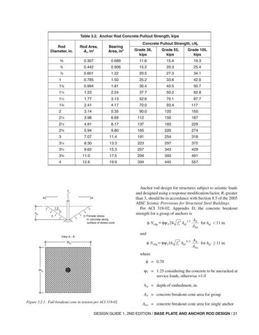
Anchor rod design for structures subject to seismic loads and designed using a response modification factor, R, greater than 3, should be in accordance with Section 8.5 of the 2005 AISC Seismic Provisions for Structural Steel Buildings. Per ACI 318-02, Appendix D, the concrete breakout strength for a group of anchors is φ N cbg = φψ 3 24 f c′ hef 1.5
AN for hef < 11 in. ANo
φ N cbg = φψ 316 f c′ hef 5 / 3
AN for hef ≥ 11 in. ANo
and
where φ = 0.70 ψ3 = 1.25 considering the concrete to be uncracked at service loads, otherwise =1.0 hef = depth of embedment, in. AN = concrete breakout cone area for group Figure 3.2.1. Full breakout cone in tension per ACI 318-02.
ANo = concrete breakout cone area for single anchor
DESIGN GUIDE 1, 2ND EDITION / BASE PLATE AND ANCHOR ROD DESIGN / 21