
MAGAZINE
2024
| MARCH/APRIL


Jennifer Knopf and Ulf W. Naatz, Vink Chemicals, Germany, and Matt Streets, Rawwater, UK, outline the options available to mitigate the challenges of reservoir souring.

16 Moving Faster
Guy Feasey, Neo Oiltools, USA, outlines how advanced technological enhancements are helping to mitigate the risks of fast factory drilling approaches.
Front cover
Reservoir souring is a process in which sulfate-reducing bacteria (SRB) utilise sulfate sources, which were introduced by sulfate-containing injection waters, and produce sulfur species, namely hydrogen sulfide (H2S). If souring is not properly controlled, it can become very costly and eventually make an oilfield economically unviable. Turn to P.10 to read Vink Chemicals’ article and learn more about reservoir souring

20 Improving Decommissioning Economics
Knut Inge Dahlberg, Baker Hughes, Norway, explains how new approaches to well plugging and abandonment can improve decommissioning economics. 24 Solving Traditional Tool Limitations
Skyler Blalock, TechnipFMC, USA, explains how new solutions are enhancing ROV efficiencies in dynamic offshore operations.
28 The Engine Room Of Change
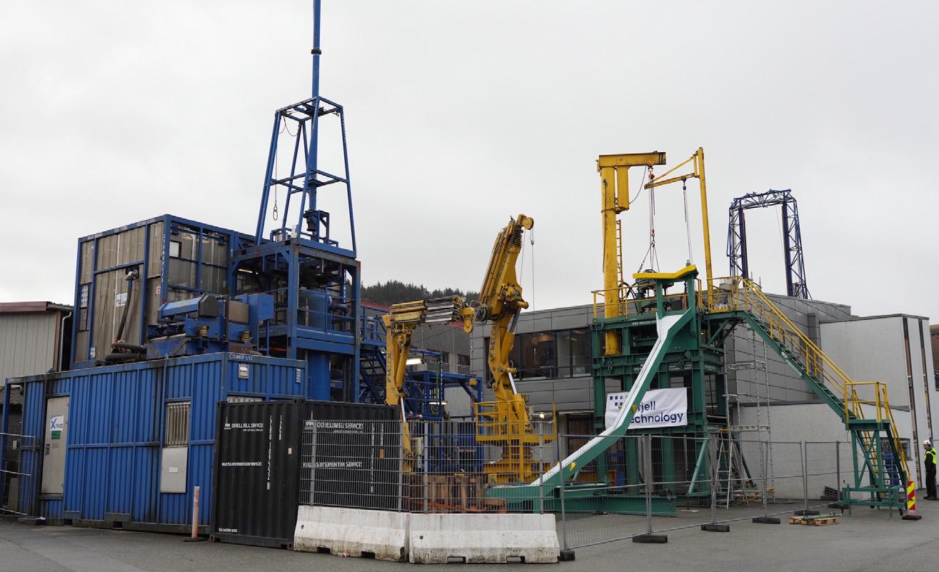
Elisabeth Haram, Odfjell Technology, Norway, outlines how fresh thinking across well intervention and well services could help meet sector challenges in terms of economy, efficiency and transition.
32 Exploring California’s Oilfields
Megan Pearl, Locus Bio-Energy, USA, and John Chafin, Cal Coast Acidizing Services, USA, discuss how biosurfactant technology is being used in California to simplify and improve acidising operations. 37 In At The Deep End


Edward Owen, Welltec, Denmark, discusses how hardware milling technology is making waves in subsea intervention.


ISSN 1757-2134 Copyright © Palladian Publications Ltd 2024. All rights reserved. No part of this publication may be reproduced, stored in a retrieval system, or transmitted in any form or by any means, electronic, mechanical, photocopying, recording or otherwise, without the prior permission of the copyright owner. All views expressed in this journal are those of the respective contributors and are not necessarily the opinions of the publisher, neither do the publishers endorse any of the claims made in the articles or the advertisements. More from Like us on Facebook Oilfield Technology Join us on LinkedIn Oilfield Technology Follow us on Twitter @OilfieldTechMag March/April 2024 Volume 17 Number 02 Contents 03 Comment 05 World News 10
Taste
Removing The Sour
.
More from Like us on Facebook Oilfield Technology Join us on LinkedIn Oilfield Technology Follow us on X @OilfieldTechMag 32 33 32 T he injection of large volumes of water into oil and typically applied during secondary and tertiary stages of conventional production and oil and gas recovery. Over the sources including seawater, aquifer water or produced water reinjection may lead to the establishment of mature microbial communities in the vicinity of the injection well or deep in the rock channels. The onset of complex metabolic processes causes raft of problems for the operator. One particular Jennifer Knopf and Ulf W. Naatz, Vink Chemicals, Germany, and Matt Streets, Rawwater, UK, outline the options available to mitigate the challenges of reservoir souring. t h e sour taste Removing challenge referred to as ‘reservoir souring’, which is the and sulfate reducing archaea (SRA) utilising various sulfate sources and eventually forming reduced sulfur species, namely become a costly process with both top and bottom-line impacts, and can eventually render an oilfield economically unprofitable. In contrast to wells producing crude oil that contains naturally occurring hydrogen sulfide, wells that produce biogenic H tell history of failed microbiological control during drilling, production and/or shut-in periods. Sulfate reducing subsurface as result of operational processes if not protected properly by a best practice treatment programme. from a sweet production asset to sour oilfield within less than decade. This was due to wells having to be abandoned by the operator during a civil war without having the time to implement industry best practice shut-in procedures for microbiological control (preservation). Therefore, produced crude increased from 11 10 10 MAGAZINE | MARCH/APRIL 2024


Our priority is the safe on-time delivery of your global energy projects. CRC Evans utilises market-leading welding and coating services, technologies and advanced data solutions, combined with a right first time approach.

Trust the experts. crcevans.com

Comment
Emily Thomas, Deputy Editor emily.thomas@palladianpublications.com

If asked to close your eyes and drift away to a ‘happy place’, you might imagine yourself on a golden, sandy beach, feeling the warmth of the sunshine on your face and soaking up the sound of waves lapping against the seashore. What you might not imagine however, is the reality of a day spent at a seaside town in the UK. Often far from idyllic, with a chill in the air and a strong sea breeze threatening to upturn your deckchair, there is also the distinct possibility of a squawking, feathered friend (or foe) swooping in to steal your chips.
That’s right, I’m talking about seagulls. Their reputation as ice cream-thieving, nuisance-making fiends has made these birds largely unpopular with human holiday makers. ‘Unpopular’ may even be putting it kindly – after all, the debate on whether these opportunistic creatures should be culled resurfaces year after year. Also not doing the seabirds any favours in the likability stakes is the age-old superstition that gulls flying together overhead is symbolic of impeding death. Let’s face it – any association with the grim reaper isn’t exactly helpful for anyone’s image.
Yet, scientists have recently swooped to their defence. Professor Paul Graham of the University of Sussex explained that the birds’ disruptive and mischievous behaviours are actually a display of intelligence. Since seagulls have been driven out of their natural habitats and into urban areas, they have been forced to adapt, which has meant feasting on whatever food they can salvage from bins and unsuspecting beachgoers alike. Emma Caulfield of The Winter Gull Survey (WinGS) also believes the gulls are no criminals – they are simply “taking advantage of the hand that’s been dealt them.”1 Perhaps then it’s time to cut the birds a beak… I mean break.
Just like the humble seabird, the oil and gas industry hasn’t always won the favour of the general public. Recent years have seen major industry players profiting from soaring energy prices, whilst many households struggled to heat their homes and pay their bills. Aside from this, concerns surrounding the climate crisis continue to grow, as well as fear for its effects on human health and biodiversity.
What often goes unrecognised, however, is that oil majors are some of the key investors in decarbonisation technologies and are enthusiastic in helping to progress the energy transition. BP, for example, is one of the major oil and gas producers branching out into offshore wind, EV charging, and hydrogen technology, as well as investigating means to lower emissions associated with its existing oil and gas facilities. Across its North Sea operations, the company plans to turn to electrification and replacement of gas turbines with cleaner energy forms. 2023 even saw BP’s global annual investment into lower carbon and other transition businesses increase from around 3% in 2019 to 23%.2 And the company is not alone – in 2023, TotalEnergies invested US$16.8 billion in low carbon energy,3 whilst Shell plans to invest US$10 –15 billion in low-carbon energy solutions by the end of 2025.4
Like the gull, the industry has had to adapt to a new future. Instead of flying under the radar, perhaps the sector should chirp up about its decarbonisation efforts and energy transition goals, in order to help reshape the way in which it is often perceived.
1. https://www.bbc.co.uk/news/science-environment-68599512
2. https://www.bp.com/en_gb/united-kingdom/home/were-backing-britain/our-transformation.html
3. https://totalenergies.com/company/transforming/ambition/investments-aligned-multi-energystrategy#:~:text=TotalEnergies%20invested%2016.8%20billion%20dollars,over%20the%20next%205%20 years.
4. https://www.shell.com/sustainability/our-climate-target/shell-energy-transition-strategy.html#iframe=L2VuZXJ neS10cmFuc2l0aW9uLXN0cmF0ZWd5LzIwMjQv
March/April 2024
Contact us
Editorial
Managing Editor: James Little james.little@palladianpublications.com
Senior Editor: Callum O’Reilly callum.oreilly@palladianpublications.com
Deputy Editor: Emily Thomas emily.thomas@palladianpublications.com
Editorial Assistant: Jack Roscoe jack.roscoe@palladianpublications.com
Design
Production: Kate Wilkerson kate.wilkerson@palladianpublications.com
Production: Kyla Waller kyla.waller@palladianpublications.com
Sales
Sales Director: Rod Hardy rod.hardy@palladianpublications.com
Sales Manager: Chris Lethbridge chris.lethbridge@palladianpublications.com
Sales Executive: Daniel Farr daniel.farr@palladianpublications.com
Website
Digital Content Assistant: Kristian Ilasko kristian.ilasko@palladianpublications.com
Digital Administration: Nicole Harman-Smith nicole.harman-smith@palladianpublications.com
Events
Events Manager: Louise Cameron louise.cameron@palladianpublications.com
Digital Events Coordinator: Merili Jurivete merili.jurivete@palladianpublications.com
Marketing
Administration Manager: Laura White laura.white@palladianpublications.com
Reprints: reprints@palladianpublications.com
Palladian Publications Ltd, 15 South Street, Farnham, Surrey GU9 7QU, UK Tel: +44 (0) 1252 718 999 Website: www.oilfieldtechnology.com

March/April 2024 Oilfield Technology | 3
Optimum Strength elastomer formulated for high torque and designed for increased reliability in high solids drilling applications
Maximum Wear elastomer designed to deliver increased durability and high torque in high performance drilling applications
High Temperature elastomer for applications requiring high power output and excellent fatigue life at elevated downhole temperatures

Elastomers
No matter what you are drilling through, or what well you are completing, we have the right elastomer compounds for the job. Specifically formulated to deliver the power, durability and maximized performance you demand.
See how we deliver nothing but power sections at Abacodrilling.com

LEADING POWER SECTION TECHNOLOGY
© 2023 Abaco Drilling Technologies. All rights reserved.
that
deliver nothing but power

World news
ADNOC announces first production from Belbazem offshore block
ADNOC has announced the start of crude oil production from its Belbazem offshore block, underscoring the company’s commitment to responsibly meeting the world’s growing demand for energy.
The Belbazem offshore block is operated by Al Yasat Petroleum, a joint venture between ADNOC and China National Petroleum Corp. ADNOC’s approach in developing the block includes leveraging operational synergies with adjacent fields, artificial intelligence and digitalisation to enhance efficiency and safety while reducing emissions and cost.
Abdulmunim Saif Al Kindy, ADNOC Upstream Executive Director, said: “The start of crude oil production from the Belbazem offshore block is testament to the success of our strategic partnership with CNPC and the robust bilateral energy relationship between the UAE and China. ADNOC continues to maximise value from Abu Dhabi’s resources, while reducing our carbon footprint to ensure a secure, reliable, and responsible supply of energy to customers locally and internationally.”
Production capacity at the Belbazem offshore block is set to progressively ramp up to 45 000 bpd of light crude and 27 million ft3/d of associated gas, contributing to ADNOC’s target of reaching 5 million bpd by 2027 and enabling UAE gas self-sufficiency for the UAE.
Al Yasat is a leader in the implementation of AI modelling and analysis tools across its offshore concession area. The Belbazem block uses WellInsight, an AI tool developed by AIQ, to analyse reservoir data and manage operations for enhanced safety and performance. The block will also integrate advanced technologies already deployed at Al Yasat’s Bu Haseer offshore field, to optimise production and reservoir management.
PGS announces letter of award for large 3D contract offshore South Atlantic margin
PGS has received a letter of award for a large 3D contract offshore of the South Atlantic margin from a multiclient company.
A Ramform Titan-class vessel is scheduled to commence mobilisation in June, with a forecast acquisition duration of up to 300 days.
“Seismic activity offshore South Atlantic margin is increasing as a result of recent exploration success, and we are very pleased with this letter of award, extending visibility for one of our Ramform Titan-class vessels well into 2025. The combination of the Ramform acquisition platform and our GeoStreamer technology is well suited for large scale exploration surveys and is positioned to deliver strong operational performance over extended time periods,” says Rune Olav Pedersen, President & CEO in PGS.
Subsea7 awarded contract in the Gulf of Mexico
Subsea7 has announced the award of a sizeable contract by Talos Energy for the Sunspear development in Green Canyon Block 78, in the Gulf of Mexico.
The project involves the subsea tie back of one production well at Sunspear to the Prince platform, 12 km to the north. Subsea7 will install the flowline and related subsea equipment at 500 m water depths.
Subsea7’s Houston office will oversee project management and installation engineering, with offshore work scheduled to begin later this year.
Craig Broussard, Vice President for Subsea7 Gulf of Mexico, said, “This award further strengthens our strategic partnership with Talos Energy, enabling early-stage collaboration for faster, more predictable project delivery.”
North Sea
Petrofac has been awarded a contract extension by BP, and is continuing to provide support across its North Sea portfolio.
Morocco
Energean has announced that it has completed the farm-in to Chariot Ltd. acreage offshore Morocco, following the receipt of all remaining approvals from the Moroccan authorities, and signed a rig contract with Stena Drilling Ltd.
Equatorial Guinea
Panoro Energy has announced that it has reached an agreement with the Government of Equatorial Guinea on the key terms and conditions for the award of offshore Block EG-23.
Brazil
Petro-Victory Energy has provided an update on the workover campaign to increase oil production in the 100% owned São João field in the Barreirinhas Basin in Maranhão, Brazil.
Italy
Fincantieri and Saipem have signed a memorandum of understanding to evaluate commercial and industrial opportunities for cooperation in the field of autonomous subsea vehicles and their integration with surface and underwater units.
In brief w March/April 2024 Oilfield Technology | 5
March/April 2024

World news
Diary dates
06 – 09 May 2024
Offshore Technology Conference Texas, USA www.2024.otcnet.org
10 – 13 June 2024
85th EAGE Annual Conference & Exhibition Oslo, Norway www.eageannual.org
17 – 20 September 2024
Gastech 2024 Texas, USA www.gastechevent.com
28 – 30 October 2024
YNOW2024 Texas, USA www.yokogawa.com
Web news highlights
Ì Saipem receives authorisation to proceed with the execution of the Whiptail project in Guyana
Ì KCA Deutag secures drilling contracts in Oman, Saudi Arabia, Peru and Bolivia
Ì Petrobras discovers oil in waters of the Potiguar Basin
Ì Odfjell Technology secures whipstock services contract with TPAO
Ì Kent wins contract with Repsol Norge
To read more about these articles and for more event listings go to: www.oilfieldtechnology.com
Prima Energy announces approval of the revised AAL oilfield plan of development
Prima Energy Northwest Natuna Pte. Ltd. (PENN) and Satuan Kerja Khusus Pelaksana Kegiatan Usaha Hulu Minyak dan Gas Bumi (SKK Migas) have concluded discussions on the revised plan of development for the Ande-Ande Lumut (AAL) oilfield.
The revised PoD was approved by the Ministry of Energy and Mineral Resources on 05 March 2024. The AAL oilfield, characterised by heavy oil, is located in the West Natuna Sea, 20 km from the Malaysian border and approximately 260 km from the nearest land (Matak, Anambas).
Deputy for Exploration, Development, and Management of Work Areas at SKK Migas, Benny Lubiantara, stated, “The development of the AAL oilfield is quite challenging due to its remote location and proximity to border areas. The oil nature in the reservoir is heavy, and there is a tendency for sand problems in the layers, requiring special handling and thus relatively high operational costs.”
The AAL oilfield is one of the hopes for increasing national oil production, considering the continuously rising oil demand. It will also be a backbone in achieving the target of 1 million bbl of oil production.
Efforts to mitigate risks related to these issues are outlined in this PoD revision, where the project will be implemented in two phases. The production facility scenarios involve the use of a central production platform (CPP) and floating, storage, and offloading. This concept represents a change from the previous concept which used well head platform and floating, production, storage, and offloading. The initial stage of AAL development will involve the installation of platform jackets and drilling of seven horizontal production wells to produce oil from both K and G sand layers.
Meanwhile, CEO of Prima Energy Northwest Natuna, Pieters Utomo, emphasised that PENN will continue to commit to the development of the AAL oilfield until reaching production by the end of 2026 with a production target of 20 000 boe/d. Challenges from the AAL oilfield include unconsolidated sand reservoirs and heavy oil, necessitating long horizontal well drilling and specialised lower completion wells to limit water and sand production.
MODEC secures FEED for Shell’s Gato do Mato FPSO project in Brazil
MODEC has announced that it has been successful in securing the front-end engineering and design (FEED) for a floating production, storage and offloading (FPSO) system for Shell do Brasil Ltda (Shell) on the Gato do Mato development, offshore Brazil.
Gato do Mato FPSO will be moored at a water depth of approximately 2000 m, some 250 km off the coast of Brazil. MODEC will be responsible for the design of the hull and all related topsides facilities for the FPSO, which are projected to be moored by a SOFEC Spread Mooring system. The produced stabilised crude will be stored in the FPSO tanks and the oil will be offloaded to shuttle tankers to go to market.
MODEC has previously delivered 16 FPSOs to Brazil and has two more under construction currently. The FPSO Gato do Mato would be the second unit to be delivered directly to Shell by MODEC for operation in Brazil.
MODEC President and CEO, Hirohiko Miyata, expressed his delight in securing the FEED project. “MODEC is proud to be working on its 19 th FPSO for Brazil and our second for Shell in Brazil. This milestone indicates the strong relationship between the two companies which now spans more than 20 years. We are excited about performing this FEED study for Shell.”
6 | Oilfield Technology March/April 2024
March/April 2024


World news
88 Energy announces oil and gas at discovery in Alaska
88 Energy has announced the successful flow testing of the Upper SFS reservoir in the company’s Hickory-1 discovery well, located in Project Phoenix on the North Slope of Alaska.
Managing Director, Ashley Gilbert, commented: “Outcomes from this test represent a significant milestone for 88 Energy and its shareholders, with the first successful flow of oil to surface achieved at the company’s Alaska projects. The completion of flow testing in this zone and recovery to surface of light oil, in addition to NGLs and associated gas, confirms our understanding of the substantial potential of these reservoirs. Significantly, these flow rates were achieved from only a 20 ft perforated section in a vertical well with a low volume stimulation over a short period. As previously highlighted, production rates in long horizontal production wells are typically multiples of 6 – 12 times higher than tested in vertical wells, as evidenced in many Lower 48 analogues.”
“Importantly, the Upper SFS zone had not previously been intersected or tested at either Project Phoenix or on adjacent acreage. It is particularly exciting for us to produce oil to surface and demonstrate the producibility of this additionally discovered reservoir. Future plans for the assessment of the commerciality of Project Phoenix will be communicated post analysis of the Hickory-1 programme.”
“We will now proceed to undertake flow testing of the shallower SMD-B reservoir over the coming weeks. This is a zone which has previously been successfully tested on adjacent acreage to the north. We look forward to continuing to update shareholders on the progress of our Hickory-1 flow testing operations.”
Seatrium and Shell to collaborate on floating production systems
Seatrium has announced that it has inked a non-binding memorandum of understanding (MoU) with Shell to explore and strengthen collaboration opportunities in floating production systems through leveraging both parties’ deep engineering capabilities and technologies.
The MoU, which focuses on driving project standardisation and replication, seeks to promote best practices in the design and construction of floating production systems. Both parties intend to leverage their experience and know-how from previous projects to mature and realise further benefits of replication, tapping on each other’s competencies and technologies and incorporating lessons learned from past projects.
Seatrium and Shell have worked together on various projects over the years, including the recently-announced Sparta floating production unit (FPU), which is conceived as a replicable project to leverage the group’s topsides single lift integration methodology, following the fabrication of Vito and Whale FPU newbuilds in 2021 and 2023 respectively.
Mr William Gu, Executive Vice President of Seatrium Oil & Gas (International), said, “We are pleased to deepen our collaboration with Shell, leveraging both parties’ competencies and technologies in past floating production systems projects. We look forward to continue working with Shell to mutually learn and develop best-in-class project management practices to achieve operational efficiency in future floater projects, benefitting both parties.”
Ocean Installer secures SLM contract with Equinor
Ocean Installer has secured a new subsea line modification (SLM) project award from Equinor on Åsgard A.
This adds more work to the multiple project wins in 2023, including projects on Vigdis, Visund, Åsgard C and Northern Lights, further strengthening their collaboration with Equinor.
The scope of work on Åsgard A covers the recovery of two risers, installation of one new riser and flexible jumper and engineering, procurement, and installation of GRP Covers to protect the jumper. Offshore operations are schedule for Autumn 2024.
In July 2023 Ocean Installer was awarded SLM Projects on Vigdis, Visund, Åsgard C and a morgrip connection on the new Northern Light CO 2 pipeline. The Åsgard A Project was won in a new competitive tender and will now be added to this project portfolio, integrated under the existing project team and executed in continuation with the other work.
“I’m very pleased to see that Equinor is adding more work to our SLM portfolio and their continued trust in us for executing these highly complex offshore operations. Integrating this project under the existing project team ensures continuity both onshore and offshore, maximising the synergies for both Ocean Installer and Equinor.”
“The short time for engineering and procurement, from contract award to offshore execution this fall, is a testimony to the competence in our organisation and close collaboration with Equinor”, said Ocean Installer CEO Kevin Murphy.
March/April 2024 8 | Oilfield Technology March/April 2024
Oil & Gas
Capture the value!
Vink Chemicals provides world-leading chemical solutions to oil and gas operations. Through innovation, we produce and supply high-performance technologies that enhance oil & gas recovery and processing, increase the value of hydrocarbons and minimize threats to personnel and the environment. Our stabicor®, grotamar® and grotan® range of oilfield chemicals can overcome the challenges presented by H2S, microbiological growth, water content and composition, paraffin deposition, asphaltenes and corrosion ensuring your operations flow smoothly and your products get to their destination in spec and on time.
Our O&G Group consists of Subject Matter Experts that harness a wealth of experience from upstream, midstream and downstream segments to deep-dive into our customers problems and deliver best-in-class solutions. We aim to meet our customer needs to reduce risks and hazards, lower costs, and improve productivity.
Capture the value at www.vink-chemicals.com and contact us!
Vink Chemicals GmbH & Co. KG
Eichenhöhe 29, 21255 Kakenstorf, Germany
Oil & Gas
Phone: +49 4186 – 88 797 0
E-mail: oilgas@vink-chemicals.com www.vink-chemicals.com
Use
safely.
the label and product information before use.
biocides
Always read
Solutions to safeguard your products
sour Removing

Jennifer Knopf and Ulf W. Naatz, Vink Chemicals, Germany, and Matt Streets, Rawwater, UK, outline the options available to mitigate the challenges of reservoir souring.
The injection of large volumes of water into oil and gas reservoirs for maintaining reservoir pressure is typically applied during secondary and tertiary stages of conventional production and oil and gas recovery. Over the lifetime of the well, such sulfate-containing water from various sources – including seawater, aquifer water or produced water reinjection – may lead to the establishment of mature microbial communities in the vicinity of the injection well or deep in the rock channels. The onset of complex metabolic processes causes a raft of problems for the operator. One particular
10 |
t h e taste

challenge is referred to as ‘reservoir souring’, which is the process chiefly dominated by sulfate reducing bacteria (SRB) and sulfate reducing archaea (SRA) utilising various sulfate sources and eventually forming reduced sulfur species, namely hydrogen sulfide (H 2S). If not properly controlled, souring can become a costly process with both top and bottom-line impacts, and can eventually render an oilfield economically unprofitable.
In contrast to wells producing crude oil that contains naturally occurring hydrogen sulfide, wells that produce biogenic H 2S tell a history of failed microbiological control during
drilling, production and/or shut-in periods. Sulfate reducing microorganisms are readily introduced to the uncontaminated subsurface as a result of operational processes if not protected properly by a best practice treatment programme.
As an example, a large onshore oilfield in North Africa turned from a sweet production asset to a sour oilfield within less than a decade. This was due to wells having to be abandoned by the operator during a civil war without having the time to implement industry best practice shut-in procedures for microbiological control (preservation). Therefore, produced crude increased from
| 11
less than 10 ppm (w/w) H 2S in the past to over 800 ppm (w/w) more recently, with the oilfield now producing about 150 kg of biogenically formed H 2S every hour.
The consequences of souring include:
Ì H 2S formation.
Ì Immediate HSE risk for field personnel.
Ì Loss of productivity.
Ì The high expense of H 2S scavengers.
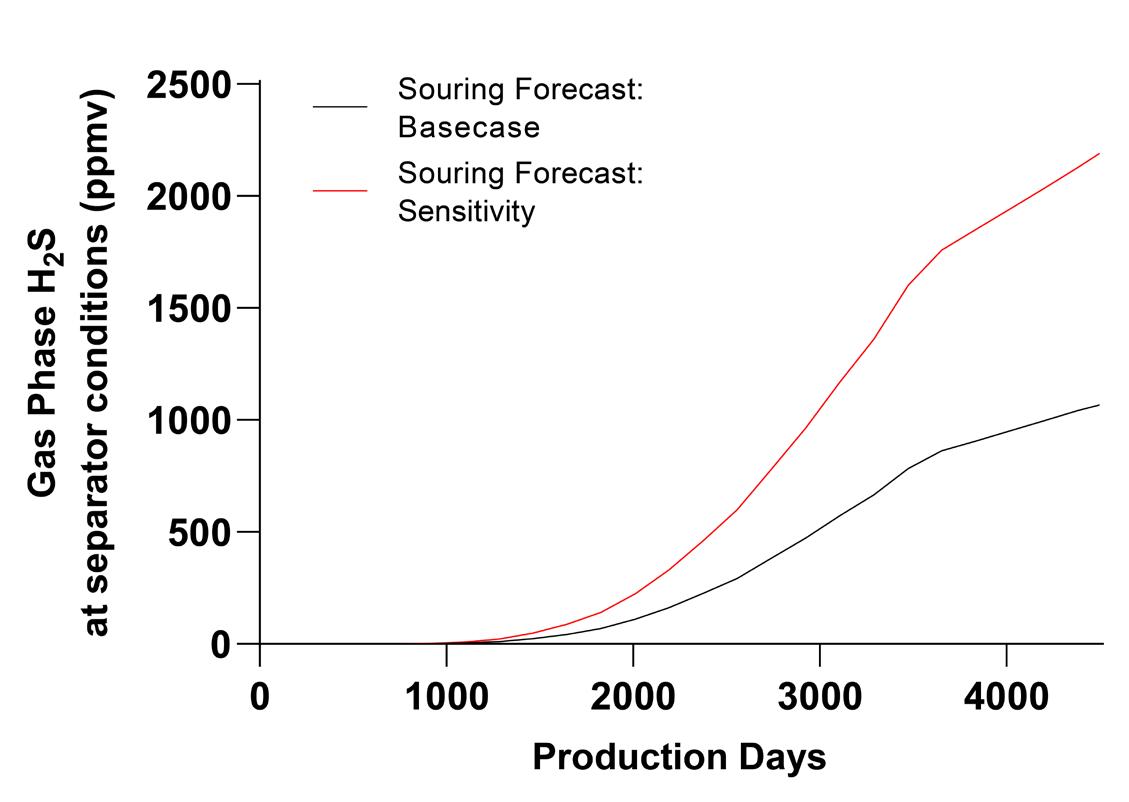
1. Basecase and sensitivity forecasts – an example of output souring profiles from Rawwater’s souring forecasting model, DynamicTVS©.
Ì Damage to production facilities, as well as leaks and spills.
Ì Biofilm and plugging.
Ì Formation damage.
Ì The replacement of assets from microbiological influenced corrosion (MIC).
Ì Reduction in oil quality and lost value from sour hydrocarbon production.
Ì Unwanted attention from investors, media, regulators and the public.
Recent trends in mitigation programmes
The first step in a reactive mitigation strategy is the implementation of a H 2 S scavenger treatment programme to quickly bring the sour crude to export specifications. However, the mass of H 2 S produced from the large North African oilfield described previously demonstrates the enormous consumption of scavenger required to remove this high H 2 S load. Established organic, non-reversible scavenger chemistries rarely act in a 1:1 stoichiometric reaction path and typically come as a 40 – 60% aqueous solution (for example MEA-triazine). Thus, the volumes of scavengers brought to the field accordingly may be high. The field produces 150 kg H 2 S/hr, which results in 3600 kg H 2 S/day. For treatment of 3600 kg H 2 S/day, with a typical treatment rate of 3 ppm scavenger: 1 ppm H 2 S, 10.8 t of a scavenger (100% active product) would be required. Industry standard scavengers come diluted, containing 40% active, which increases the needed scavenger volume to 27 t scavenger (40%) per day.
Taking the chemicals cost for a permanent H 2 S scavenger treatment into account, it appears logical to alternatively (and sometimes additionally) focus on the root causes of biogenically formed H 2 S, firstly the biofilm, and secondly, the volume and quality of the injection water. In the first case, a specifically designed biocide treatment for the well and its near wellbore area may be a sustainable and cost-effective solution compared to a permanent, continuous H 2 S scavenger treatment. However, if the biofilm has spread deep into the formation, any cost-effective biocide treatment will be ineffective, and the potential risk of formation damage during deep squeeze treatments may be considered too high. Alternative treatments may employ specific treatment of the injection water to control or alter the primary metabolic processes by SRBs within the formation during the transit of the water from the injection well to the producing well (i.e. biocides or nitrate). Another mitigation strategy is the removal or significant reduction of the sulfate content from the source water prior to injection. This is typically achieved by implementing membrane technologies or other water pre-treatment methods which facilitate the precipitation of the sulfate ion. Coupled with scale control, this methodology has been shown to significantly reduce sulfate reducing activity in the downhole formation, but like other water injection treatment strategies, the effects are only visible upon breakthrough of the injection water, which can take months or even years.
Reservoir souring modelling
Rawwater Engineering Company Ltd. (Rawwater), as a third-party, independent specialist in oilfield reservoir souring, supports Vink Chemicals in oilfield reservoir souring modelling and high-pressure laboratory simulations.
12 | Oilfield Technology March/April 2024
Figure
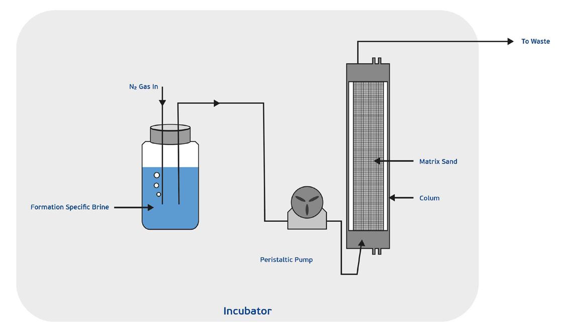
Figure 2. FFUBR test set-up.
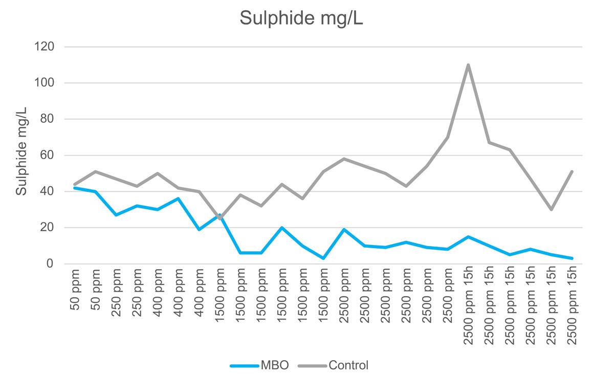
Figure 3. Sulfide measurements.


Mastering Well Control Challenges:
Where Advanced Engineering Ensures Safe Solutions


Wild Well Control is at the forefront of cutting-edge engineering and well control services within the oil and gas industry. Prioritizing safety and ingenuity, our experienced professionals promptly handle wellbore complications, demonstrating expertise in intricate situations.
Our distinguished rapid response encompasses sealing maneuvers in the harshest of circumstances. Moving beyond conventional drilling, Wild Well's skilled engineering unit partners with clients to reinstate standard drilling conditions. Our proficient well control staff guarantees the secure management of well control occurrences, drawing upon extensive proficiency in both established and innovative methodologies.


Contact us for all your well control needs. +1 281.784.4700 / WILDWELL.COM
Predicting the appearance and severity of sour fluid production through computer models is crucial for making significant technical and economic decisions related to field development and material selection. Whilst the intricacies of modelling microbial sour gas production are complex, a credible souring forecasting model should describe four key mechanisms:
Ì Cooling of an oilfield reservoir as a result of waterflooding.
Ì The opportunity for the growth of sulfate-reducing microorganisms in the waterflood.
Ì Transport of the hydrogen sulfide from the ‘downhole bioreactor’ created to the production well(s).
Ì The partitioning of the sulfide species at specified pressure and temperature conditions at the production facilities.
Souring modelling is also vastly improved through the ease at which history matching of field H 2S data can be conducted, as well as sensitivity analysis and processing under short computational turnaround times. Over the past 30+ years, numerous mathematical souring models of varying dimensions have been created to aid in forecasting the potential for microbial oilfield reservoir souring (Figure 1).
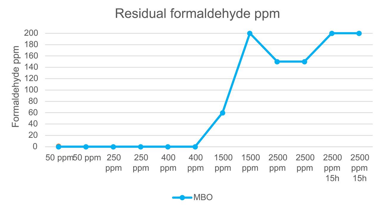
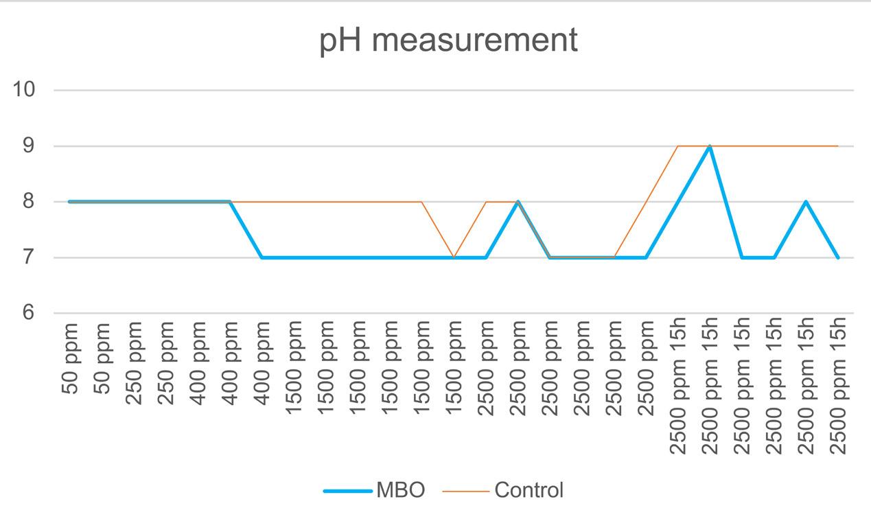
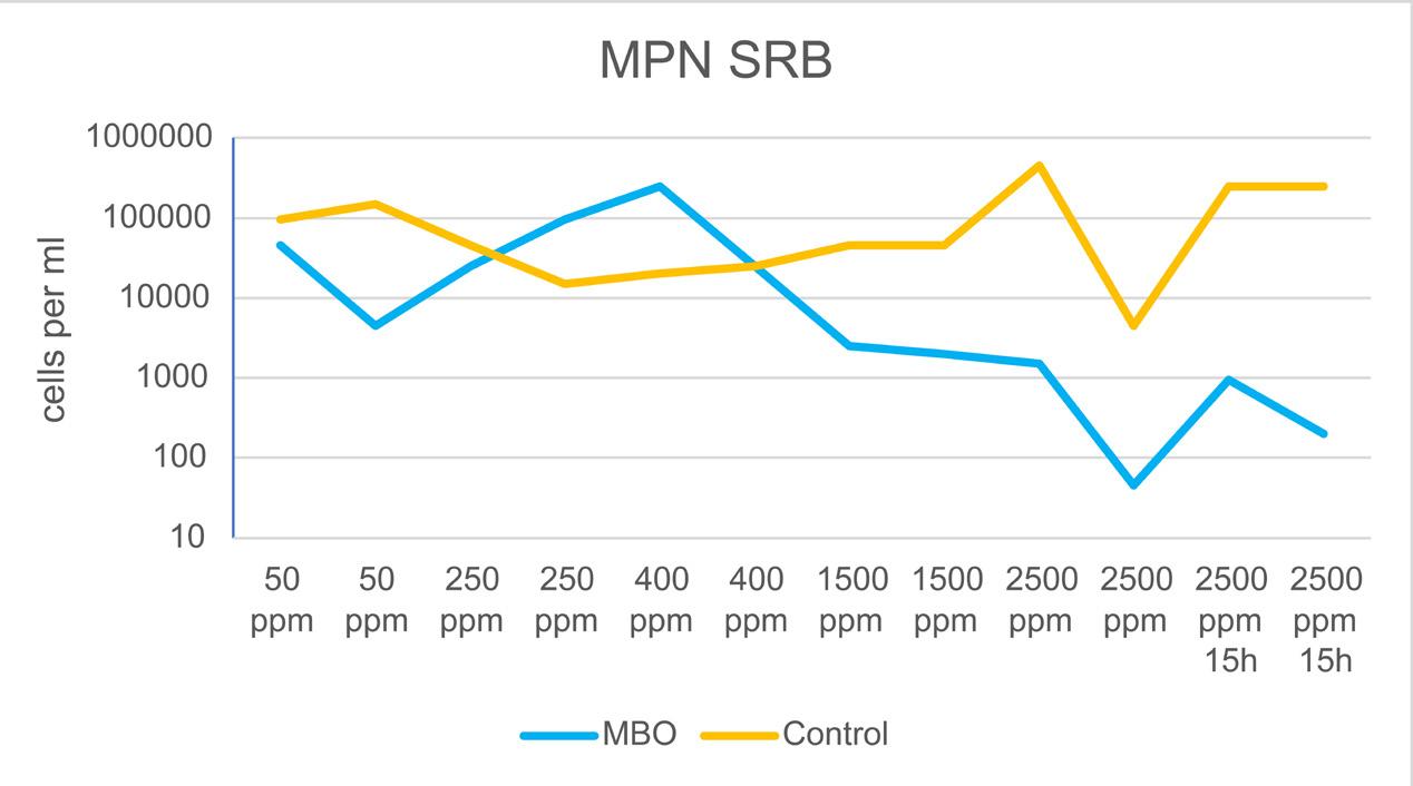
Figure 6. Most probable number of SRB. This graph demonstrates that the biocide MBO successfully reduced the SRB count at a higher dosage rate by 2 – 3 log.
One of these models was the DynamicTVS © souring forecasting tool which is owned and operated by Rawwater. Initially developed in the late 1980s, the souring module, which was first published in 1993, interfaces with 4D simulators which can be operated by various industry disciplines without the need for a background in reservoir engineering. As part of their continual development, tools such as the DynamicTVS model and the ESSS ‘SourSimRL’ simulator, use asset data and field observations, as well as kinetic data from laboratory-based, high-pressure bioreactor studies like those conducted at Rawwater, to further improve and advance their souring forecasting capabilities. In summary, oilfield reservoir souring forecasting and modelling contribute to improved operational efficiency, reduced costs, enhanced safety, environmental compliance, and optimised reservoir management throughout the lifecycles of oilfields.
Souring mitigation techniques
As mentioned previously, an exclusive topside H 2 S treatment is not always the most economical solution. A successful treatment lies in additionally addressing the root cause, microbiologically-formed H 2 S. Controlling reservoir souring requires the use of an effective biocide that can reduce contamination and prevent significant bacteria growth. Traditional biocides for microbial mitigation are typically implemented under short-lived, high-dose applications. Long term protection biocides for microbial control aim to achieve long-term preservation and are key to more successful production operation and extended asset life. Vink Chemicals’ biocide grotan® OX is suitable for both short-term and longer-term strategies so operators can plan and be assured of smooth well operation. Such biocides can:
Ì Control CAPEX, reduce operating/high maintenance costs, and ultimately avoid well shutdown.
Ì Improve efficiency in reducing SRB – the main source of H 2 S souring.
Ì Ensure fast acting and long-lasting biocidal activity for short-term disinfections and long-term preservation.
Ì Offer water and oil soluble properties to multiphase environments.
Ì Offer a wide pH tolerance for variety of oil and gas environments.
14 | Oilfield Technology March/April 2024
Figure 4. Detection of residual formaldehyde.
Figure 5. pH measurements.
Laboratory souring simulation: bioreactor test
Summary
In this experimental setup, the biocide grotan OX (MBO, 3,3′-methylenebis (5-methyl-oxazolidine), CAS: 66204-44-2) showed significant biocidal efficacy. The performance was demonstrated by the reduction of SRB, GHB and APB bacterial counts and the reduction of sulfide levels. This test demonstrated that MBO is a suitable candidate for a cost-effective reservoir souring treatment programme. The testing was performed by the third-party lab, Intertek UK laboratories.
Test set-up
One biocidal product was assayed against general heterotrophic bacteria (GHB), acid-producing general heterotrophic bacteria (APB) and sulfate reducing bacteria (SRB) to compare the efficiency of its biocidal action. For this testing, fixed film up flow bioreactors (FFUBRs) were utilised (Figure 2). The packing matrix used was sand, saturated with seawater (35 000 TDS – already set-up), and then eluted with the same water containing SRB and GHB (in-house cultures).
Set-up consisted of three FFUBRs at 50°C. After a period of microbial community establishment, treatment commenced with the lowest test concentration under pulse treatment, once a week for two weeks before increasing the concentration in increments. The efficacy of the chemicals was tested by measuring various parameters throughout the course of testing such as pH and sulfide at the inlet and outlet. At the end of each phase (pulse treatment), bacterial enumerations were performed on the outlet fluids by MPN culture methods, as well as residual formaldehyde measurements. The NACE International Standard TMO 194-2014 was used as a guideline in the design of these tests.
Methodology
Samples were collected on a regular basis on the outlet of the FFUBR, with periodical sampling on the inlet to determine various parameters:
Ì Sulfide assay by XION 500 and pH at the outlet.
Ì Bacterial enumerations on the outlet fluids by MPN culture methods.
Ì Residual biocide at the outlet – using the semi quantitative formaldehyde test kit from Quantofix™.
Results
A significant decrease in sulfide concentration was achieved by the biocide MBO (Figure 3). There are two effects behind the drop in sulfide concentration: the scavenging of sulfide and the reduction of active SRB, which significantly reduced sulfide production. The successful decrease in sulfide concentration indicates good efficacy of MBO.
Residual ppm(w) formaldehyde was detected during treatment with MBO (Figure 4). This observation indicated that there was an excess of MBO available after scavenging the H 2S present, providing sufficient free formaldehyde for biocidal control.
The pH values of the test media did not change significantly during the test period (Figure 5). This indicated a strongly buffered system that is not significantly affected by the addition of alkaline chemicals.
Conclusion
The biocidal active ingredient MBO, 3,3′-methylenebis(5-methyloxazolidine), showed good performance against high levels of contamination with SRB, GHB, and APB (Figures 6 – 8). In addition, the amount of sulfide was significantly reduced. Unreacted, unconsumed formaldehyde residues were detected, indicating excess dosing, meaning dose rates can be optimised and reduced. This test setup simulated a worst-case sour reservoir scenario, with a strongly established biofilm. Therefore, MBO can be recommended as a suitable biocide product with a favourable price/performance ratio to mitigate the souring of the reservoir downhole (Figure 9).
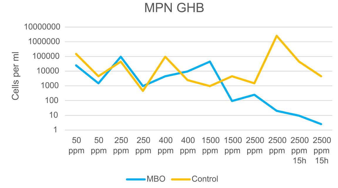
Figure 7. Most probable number of GHB. As can be seen, MBO was able to significantly reduce the GHB count at higher doses.
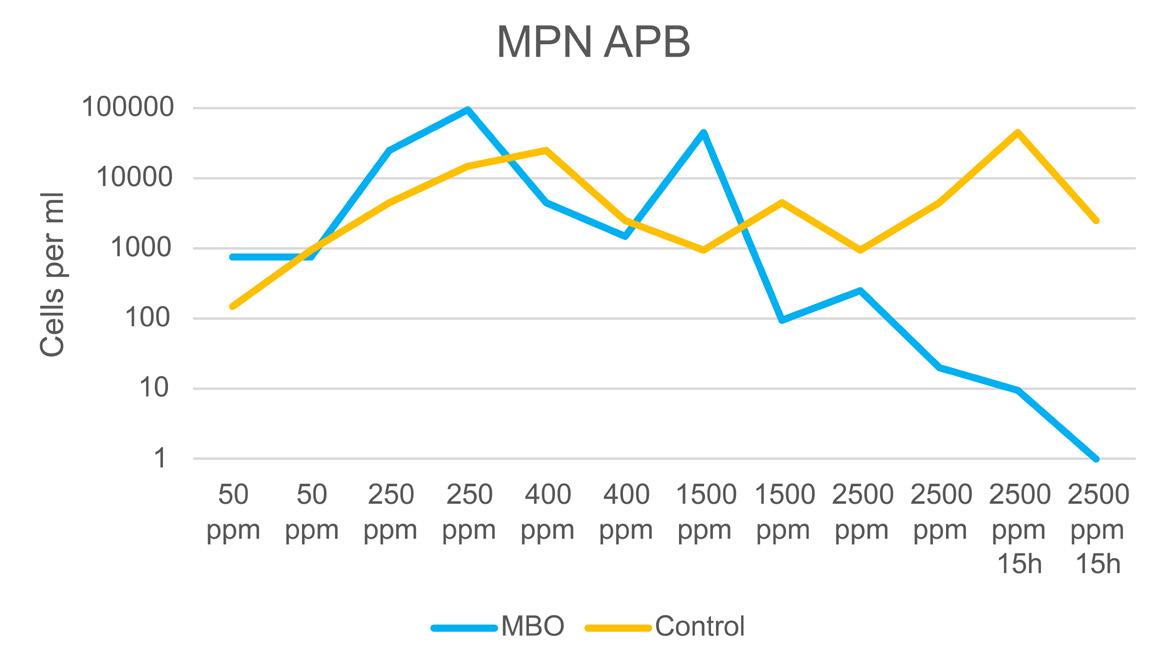
8. Most probable number of APB. The biocide MBO was able to reduce the APB count to an acceptable level.
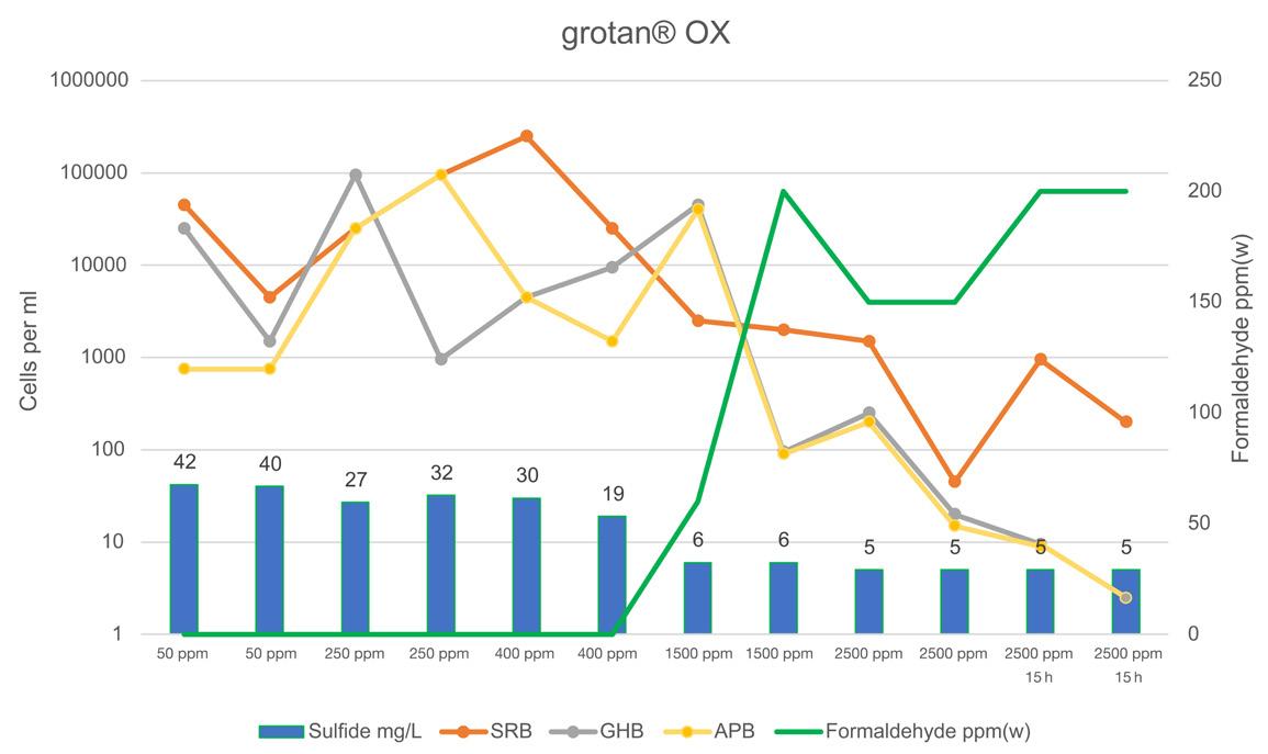
Figure 9. Overview of collected lab data (sulfide/residual formaldehyde/MPN SRB, GHB, APB).
March/April 2024 Oilfield Technology | 15
Figure
Guy Feasey, Neo Oiltools, USA, outlines how advanced technological enhancements are helping to mitigate the risks of fast factory drilling approaches.


16 |
As operators and drilling companies strive to drill farther faster, challenges are encountered in the field that not only risk the integrity of the drill bit and electronics but also stand to increase equipment costs and downtime. Technologically advanced drilling enhancements can help mitigate these risks.
Drilling dysfunctions
A vibration suppression system (VSS) is a generic term used today to describe a drill-string or bottom hole assembly (BHA) component intended to dampen any form of vibration that may cause dynamic drilling dysfunction caused by axial, lateral or torsional vibrations. The term ‘VSS’ does not generally differentiate whether a tool addresses one type or multiple types of vibration, nor will this term break down the VSS tool’s ability to address the amplitudes and frequencies which manifest
themselves in different forms of dysfunction such as ‘stick-slip’, or ‘high frequency torsional oscillations’ (HFTO).
Individual VSS tools can be used to address the specific consequences of various drilling dysfunctions, however no one tool typically can capture them all. In every case, the root cause of any drilling trouble always begins at the bit.
There are four key drilling dysfunctions encountered in the oilfield, and typically, VSS tools only address either axial, stick-slip, HFTO (sometimes referred to as tangential vibrations) or lateral dysfunctions. Axial shocks move the drill string along the axis, which can result in damaged downhole tools and a slowed rate of penetration (ROP). Springs can be employed to dampen this type of shock.
Low-frequency torsional shocks (stick-slip) occur when the bit digs into the formation deeply enough to slow it down relative to the drill string, causing reactive torque. This can fatigue the drill


| 17
string and BHA in different ways depending on the amplitude and frequency. One example of a tool that responds to torque in this way is a design with internal helical splines.
HFTO is torsional instability with a resonance frequency much higher than stick-slip that can seriously damage drilling tools and electronics. There are some types of VSS tools designed specifically to reduce the severity of HFTO, but in doing so, also removes the energy intended for the drill bit.
Lateral vibrations result from lateral motion of the BHA bouncing from one side of the wellbore to the other. The source of this type of vibration is caused by the drill string interaction with the wellbore and the presence of doglegs or micro-doglegs. Elastomers are commonly used to minimise lateral vibrations, however, improving the wellbore quality by using the right tool selection in the BHA design can positively affect this by improving drilling dynamics.
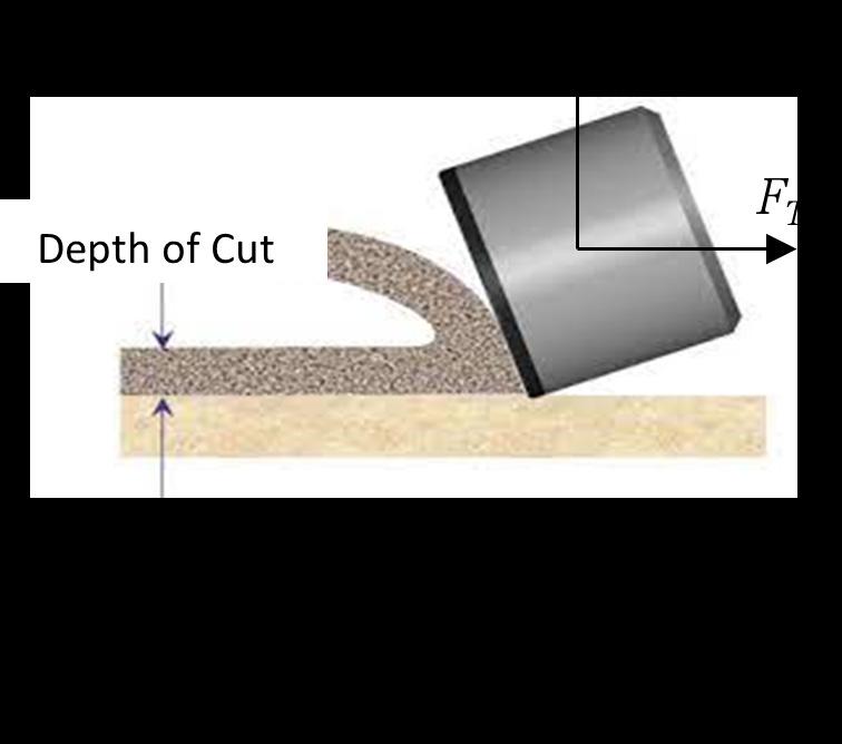
The challenge with each VSS tool option is that each is designed for a specific type of vibration or shock. In many instances, the tools are unable to manage the drill bit depth of cut to also enhance drilling by improving ROP.

Advantages of a cable design
Adding multiple VSS tools simultaneously in the BHA to mitigate several types of drilling dysfunctions for multiple wells can lengthen the BHA and increase costs significantly. Identifying a designed tool that can absorb more than one dysfunction will reduce costs while improving drilling performance. A cable design with a spring pack, where axial movement is unimpeded by the cable mechanism, is field-proven to reduce all four types of drilling dysfunctions, while enhancing drilling speeds, protecting the BHA and maintaining a constant depth of cut. Located in the BHA, it relies on a combination of disc springs and a swivel mechanism to automatically control the drill bit’s depth of cut, based on torque.
The cable design works on a novel principal; all the cables, which are a fixed length and transmit the torque, are guided around an internal mandrel. When any torsional force is added that exceeds the setting of the tool, the cables will wrap around the internal mandrel – contracting and shortening its length.
The cables are flexible during compression and strong in tension. When responding to torque, the only friction that the cable design has to overcome is when the cables slide across the mandrel. In the case of a sudden axial shock, the flexible cables offer no resistance. This enables the cable design to respond faster to changes in formation while drilling no matter the bandwidth of vibration frequency (high or low), maintaining undisturbed engagement between PDC cutters and the formation. Additionally, the BHA is protected which reduces unplanned expenditures due to vibration related damages.
Increasing drilling efficiency
A wellsite in the US deployed the cable design VSS tool, NeoTork, on a batch drilling operation to reduce vibrations downhole. In addtion to reducing vibrations, the operator sought to rerun the directional drilling assembly, rotary-steerable system (RSS) and measurement while drilling (MWD), on at least two consecutive wells while improving on the offset well’s ROP.
The operator had previously experienced significant tangential vibration increases in the heel of the lateral. However, using the cable design VSS tool proved to substantially reduce tangential vibration magnitudes across the entire lateral length, as well as lower axial vibrations. Tangential vibrations decreased so greatly in one well that the operator was able to rerun the entire rotary steerable and MWD system on the next well, which reduced operating costs and protected the integrity of the bit. Even at drilling rates of 500 ft/h, a 10% speed increase was achieved by minimising vibrations which demonstrates the important impact a VSS tool can have on drilling operations.
With such improvements in drilling performance, the cable design VSS tool has been adopted by many drilling companies across most major basins in the US, pushing drilling limits with respect to ROP while also alleviating supply chain issues related to tool replacements.
Faster drilling in challenging conditions
As companies increasingly opt for a fast factory drilling approach in the oilfield, drilling dysfunctions are becoming more prevalent. Vibrations and shocks can cause catastrophic equipment failure downhole and negatively impact drilling performance, which drives up costs and downtime. Minimising all types of drilling dysfunctions reduces bit and BHA damage, which can reduce trips and increase drilling efficiency. Successfully reducing downhole vibrations and shocks also enables operators to rerun assets, which yields important cost savings.
18 | Oilfield Technology March/April 2024
Figure 1. A cable design vibration suppression system tool mitigates all four types of drilling dysfunctions to push drilling limits.
Figure 2. Each vibration suppression system tool option is designed for a specific type of vibration or shock. In many instances, the tools are unable to manage the drill bit depth of cut to also enhance drilling by improving ROP .


Gastech 2024 show floor features include:
Hydrogen zone
Accelerating towards a hydrogen-powered decarbonization

Climatetech zone
Gastech is the largest energy exhibition and conference for natural gas, LNG, hydrogen, climate technologies, low-carbon solutions and energy manufacturing - providing the defining answers of the coming decades as the world decarbonizes its energy system.
Decarbonizing the energy value chain

50,000 800 20
Attendees Exhibitors International pavilions

5,000 Delegates
Shipping and Marine zone
Investing in LNG infrastructure and decarbonizing the marine value chain
1,000 Speakers
125 Countries 500 Ministers and global energy CEOs
Supported by: Host City: Organized by:
Transforming energy through vision, innovation and action
FIND OUT MORE
gastechevent.com

Knut Inge Dahlberg, Baker Hughes, Norway, explains how new approaches to well plugging and abandonment can improve decommissioning economics.
20 |

ecommissioning is a significant financial commitment for operators around the globe, and because of the amount of money required to meet asset retirement obligation liabilities, companies are continually looking for ways to streamline the process.
According to Offshore Energies UK’s ‘Decommissioning Insight Report 2023,’1 approximately £1.6 billion was spent on decommissioning on the UK Continental Shelf (UKCS) in 2022, the highest total annual expenditure to date. Forecasts indicate the amount spent in 2023 will be even higher, topping out at around £2.2 billion. Table 1 shows the extent to which well decommissioning activities increased year on year from 2022 – 2023. The report states that on average, the UK will decommission more than 200 wells per year until 2032.
Estimates published by the North Sea Transition Authority (NSTA) in its ‘Decommissioning Cost and Performance Report 2023,’ in August, indicate £21 billion will be spent on UKCS decommissioning between 2023 and 2032.2 The data shows that the North Sea oil and gas industry spent £8 billion decommissioning redundant wells and infrastructure from 2017 to 2022.
According to the NSTA’s interactive ‘Wells Insight Report 2023,’ which is based on data sourced from the UK Stewardship Survey 2017 – 2022, and the Well Operations Notification System from January 2023, there will be 2165 wells decommissioned between 2023 and 2033.3 Figure 1 shows the number of wells scheduled for plugging and abandonment (P&A) through 2032. Other areas of the world have similarly high numbers of wells that will soon require P&A. According to a study published in Nature Energy, there are more than 14 000 unplugged oil and gas wells in the Gulf of Mexico (GoM) that will have to be addressed at an estimated decommissioning cost of US$30 billion (more than £24 billion).4
The enormous volume of work required to execute all these decommissioning programmes means that resources, from rigs to equipment to personnel, will be in high demand. This poses a formidable challenge for the industry.
The NSTA ‘Wells Insight Report 2023,’ suggests that with the number of fields reaching cessation of production (CoP), there could be a move towards greater collaboration among operators that might elect to share the cost of light intervention vessels and rigs across multiple well decommissioning campaigns.3 While this will help owners execute decommissioning programmes and defray costs, it is only a partial solution.
| 21
To capture cost savings at scale, the industry needs much more than a broader effort to share resources. A better approach towards P&A is needed.
Breaking with tradition
For years, the industry has followed the same basic approach to decommissioning. Where well data is available, engineers gather all the information they can to get the best possible picture of the condition of the wellbore, and then develop a P&A programme designed to contend with anticipated challenges. In cases where data is insufficient to create a picture of downhole conditions (for example, for extremely old wells for which there are no records and for wells that have changed hands multiple times, leaving the current owners with incomplete historical data) the P&A plan unfortunately, is more like guesswork than a roadmap. Insufficient data is also a concern in the sphere of tubing and casing integrity. In these cases, the condition of the tubing and casing only becomes apparent during the P&A process, which can lead to additional work, significantly exceeding the planned budget.
In these cases, one of two things generally happens. Either the P&A plan is undertaken (often with a rig) without the necessary data, and progresses until it hits a snag (such as a collapsed pipe or a stuck tool), or costly slickline or wireline surveys are performed from the intervention vessel to get a better sense of well conditions before the P&A process begins. In both scenarios, the total cost of operation (TCO) of the P&A programme increases.
In the past, added costs were unavoidable when there was insufficient historical well data to create a complete P&A plan, but technology advances combined with a new approach to P&A planning are changing the status quo.
Leveraging technology
Understanding the unique downhole conditions of each individual well is vital to executing a successful P&A plan, because even
Table 1. Well decommissioning activities increased y/y from 2022 – 2023. (Source: Offshore Energies UK ‘Decommissioning Insight 2023’).
Decommissioning activity 2022 (actuals) 2023 (forecast)
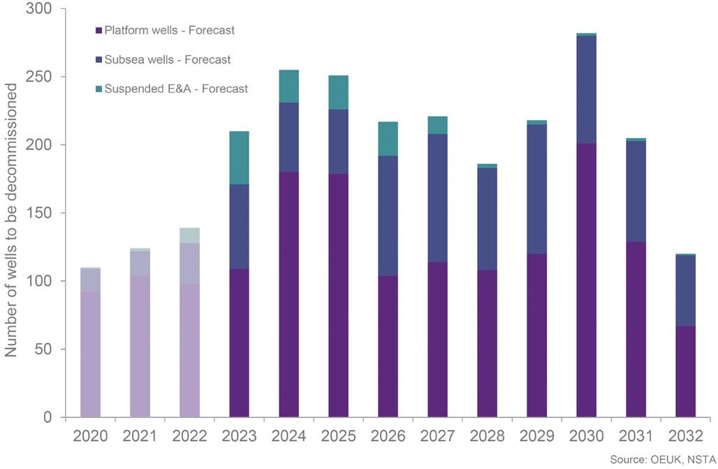
Figure 1. Data for the North Sea indicates that more than 200 wells are planned for decommissioning each year for the next few years. (Source: Offshore Energies UK “Decommissioning Insight Report 2023”).
wells drilled in the same field develop different characteristics as they age.
Today, subsurface teams are much more involved in P&A activities than they were in the past. Taking a multi-disciplinary approach, they paint a detailed picture of the subsurface, selecting each barrier location and enabling better barrier placement to prevent fluid loss, and in some cases capitalising on nature to use the caprock (geological confining) formation itself as a barrier.
In instances where historical subsurface data is not available, essential information can be collected using highly specialised and accurate downhole tooling. In many wells, lightweight and easily portable slickline tools can be used to measure parameters such as pressure, temperature, and wellbore integrity, and transmit the measurements to the surface using electrical signals or operate in memory mode. In addition, electric wireline solutions offer a practical way of simplifying the data-gathering process, and the ability to deploy a range of tools via wireline means milling, logging, and cleanup can easily be performed rigless or riserless, which precludes the need to mobilise a rig.
Logging capabilities have significantly improved and now employ advanced sonic and ultrasonic signals to differentiate among cement formation and settled barite behind casing. These advancements mean better selection of barrier placement methodologies and better planning. Further advancements are being made in the development of through-tubing logging, which will enable casing annulus logging without removing the tubing, potentially reducing well abandonment costs by a significant margin.
More data delivers better insights, and the ability to put high quality data in the hands of experts improves and expedites decision making prior to rig operations. Allowing specialists in a range of disciplines to access field data provides them with the tools to develop and optimise a P&A programme. In addition, leveraging a team of subject matter experts through remote operations centres during project execution not only helps the crew on location make the best decisions, but it also requires fewer offshore workers and reduces the total carbon footprint.
As with many other processes, decommissioning programmes are now benefitting from digital and artificial intelligence (AI). Working with a pool of data compiled over various P&A programmes, algorithms are being applied to streamline the P&A process, and as the pool of data expands, AI is enabling even more precise predictions.
One team, better results
In the past, it was common for an operator to enlist an in-house team to gather and analyse the available field data and devise a P&A programme that it shared with the multiple service companies it had contracted to perform the work. Even with the most precise P&A plan in hand, the service companies inevitably ran into unforeseen challenges that introduced complications in execution.
It was apparent that involving one integrated service company early on in the process would allow a broader team of experts to bring to bear experience and insight that could eliminate some of the unanticipated well abandonment planning issues. Investing in pre-P&A planning with a dedicated operator/service company team would streamline processes that would deliver cost savings down the road.
The ‘one team’ approach introduced by Baker Hughes allows the operator and service provider to work together months ahead of the decommissioning programme to learn about the well conditions and use those learnings to optimise the
22 | Oilfield Technology March/April 2024
Wells 139 wells 210 wells 98 platform wells 109 platform wells 30 subsea wells 62 subsea wells 11 E&A 39 E&A
final programme. Together, the team works to understand and solve potential problems, develops a strategy for resolving those problems drawing from multiple areas of expertise, determines which activities can be done effectively offline (before mobilising a decommissioning vessel/rig to the wellsite), and de-risks operations by optimising solutions before vessel/rig operations start.
The process begins with evaluating the subsurface, looking at well conditions, examining potential flow evaluations, determining the overburden pore pressure, and conducting crossflow analysis. Geologic evaluations take place at this stage, along with subsurface analysis of cement records, identifying what is behind the casing, and determining what type of fluid remains in the well. All of this information feeds into a pre-planning programme that outlines the work the wireline team will do when it is deployed to the site in advance of the P&A programme.
Normally, a wireline programme includes representatives from different companies providing slickline, logging and tractors, etc. Bringing a broad range of functions into a single team enables better analysis and produces a simplified work plan that can be executed by a smaller on-site crew. Furthermore, the type of work included in the pre-P&A programme can be carried out off the critical path, using a less advanced vessel with a lower day rate or offline on platforms. With this approach, fewer workers are required on site to carry out all the functions using tools and solutions from a single provider — from tractors, to downhole tools used during slickline and logging operations — with remote support from an expert team.

The one team approach allows fewer people at the wellsite to carry out more work with more capable equipment that requires less rig-up and rig-down time.
Putting the solution to work
Using an integrated team approach for the first time on a large, North Sea decommissioning project, a crew safely plugged and abandoned the first nine wells one month ahead of the best anticipated project timeline. With a thorough understanding of the challenges, it was possible to reduce rig time, saving a substantial amount of money.
Because regulations vary from one region to another, it is critical that the planning team understands the relevant regulations so the correct types of barriers are placed to meet local requirements. It is also important to meet the operator’s internal requirements to be able to execute successful P&A programmes around the world.
This approach has streamlined the P&A programme, saving operational time and cost per P&A operation. In the North Sea, where a single P&A takes between 14 – 30 days following the pre-P&A planning process, P&A time was cut by up to 20%. Widely applying this approach not only enables the execution of more effective P&A programmes with fewer resources; it also has the potential to deliver millions in cost savings.
References
1. https://oeuk.org.uk/product/decommissioning-insight-2023/
2. https://www.nstauthority.co.uk/media/lnmhqq2l/decom-cost-report-2023final-accessible-1.pdf
3. https://app.powerbi.com/view?r=eyJrIjoiNjkzYjNmMWU tMWY2MS00OGY4LThmYWItN2UxMDM5NmRjODIyIiw%20 idCI6ImU2ODFjNTlkLTg2OGUtNDg4Ny04MGZhLWNlMzZmMWYyMWIwZiJ9
4. https://www.nature.com/nenergy/volumes/8/issues/5
Omnetics specializes in application-specific connector to cable systems. Our expert designers have experience designing harnesses for complex and harsh environment applications. Omnetics designers have the necessary experience needed to meet the Quality and Performance specifications required by the US Military, NASA and ESA.
We design and manufacture a wide range of custom cable solutions to support all of our various product lines, while allowing your team to guide the design.
Omnetics Connector Corporation follows IPC/WHMA-A-620 for all cable assembly, test and inspection practices.
www.omnetics.com | sales@omnetics.com

Solving traditional tool limitations
Skyler Blalock, TechnipFMC, USA, explains how new solutions are enhancing ROV efficiencies in dynamic offshore operations.
24 |
Whether it be for survey, construction, or maintenance, offshore oilfields rely on remotely operated vehicles (ROVs) to complete work. For decades, these machines have allowed operators to push the limits of the reservoirs that are developed. As fields move into deeper waters, the stakes rise when it comes to costs and schedule. Complexity, uncertainty, and errors in ROV operations can take extra time, resulting in a pause in operations, or possibly damage to subsea equipment. It can take hours, days, and sometimes

weeks to recover from an interrupted scheduled operation or damaged equipment. A major source of these project profitability detractors stems from traditional ROV tooling.
ROV operations begin with an assumption about tasks and a prediction as to what associated tooling will be required to perform the tasks. Scope on an offshore job is regularly in flux, and when the initial assumptions are no longer accurate, traditional tooling requires a trip back to the deck to reconfigure in the middle of an operation.
The pilot technicians operating ROVs have a difficult task at hand. They must know how the machine works, how to interface tooling, and how to operate it in extreme conditions. Placing so much reliance on pilot knowledge and know-how means the probability of errors increases. Common events such as dropped tools, damaged subsea equipment, over-pressuring a test, over-torquing a valve, or applying too much torque to an asset brings uncertainty into operations. This uncertainty is mitigated by increasing
| 25
training for personnel, having extra tools onboard the vessel, and extra time in the schedule, which increases project costs.
TechnipFMC has examined the problems caused by traditional ROV tooling; it became clear that the trips back to the vessel deck had to be reduced and that the manipulator must be designed to eliminate damage to tools and subsea assets.
The company launched Athena™, a hydraulic tooling interchange system, to perform remote underwater work. The hydraulic tooling interchange system can be integrated into existing work-class ROVs, extending the current capability of an ROV through its wrist technology and tool storage options. The technology was built to perform subsea tool interchanges
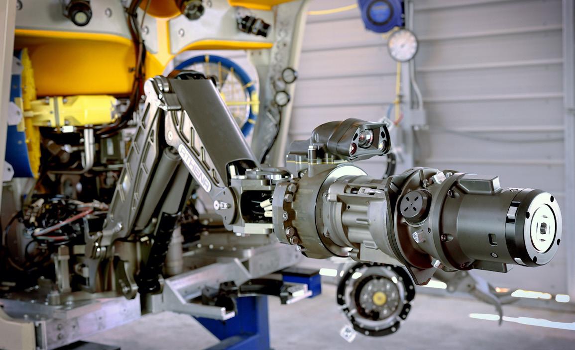
more reliably, with less risk, and to be operable by pilots at many skill levels.
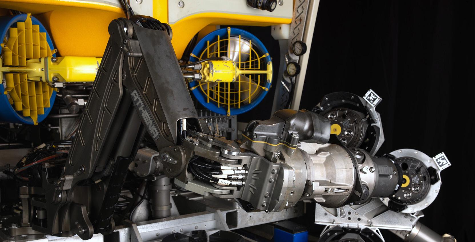
New technology such as this allows pilots to acquire and operate tools at the subsea worksite through one interface. At every tool change, the correct mechanical, hydraulic, communications, and power connections are made. This interface allows pilots to focus on the task at hand. There is no requirement to integrate individual tools with hydraulic hoses, or power connections, because all utilities pass through the arm. All that is required is loading the tools into their respective portals before a dive. This tool change functionality drives schedule certainty into operations.
With subsea tool changes possible, trips to the vessel now could be reduced by storing the tools at the worksite. To make a wide variety of tools available at the worksite, the standard and large porch tool holders allow for tool storage on the ROV’s frame or opposite manipulator. If the standard tool storage options do not work for an operation, additional tool holders can be mounted on any deployable subsea structure, enabling tooling access at the worksite.
With the subsea tool change and tool storage problems solved, there is no longer a need for the ROV to return to the vessel mid-job. The operator can now outfit the tool slots to prepare for the unpredictable. For example, during an ROV operation with traditional tooling, only one set of jaws is available to perform all tasks because it is permanently attached to the manipulator. This often requires an operation to be performed using a sub-optimal tool, taking longer and with inconsistent or unpredictable results. With this system, multiple jaw types can be deployed subsea, allowing the operator to select the jaws fit for a specific purpose, ensuring the operation is performed as intended. The options available are only limited by the tool deployment method built into the job.
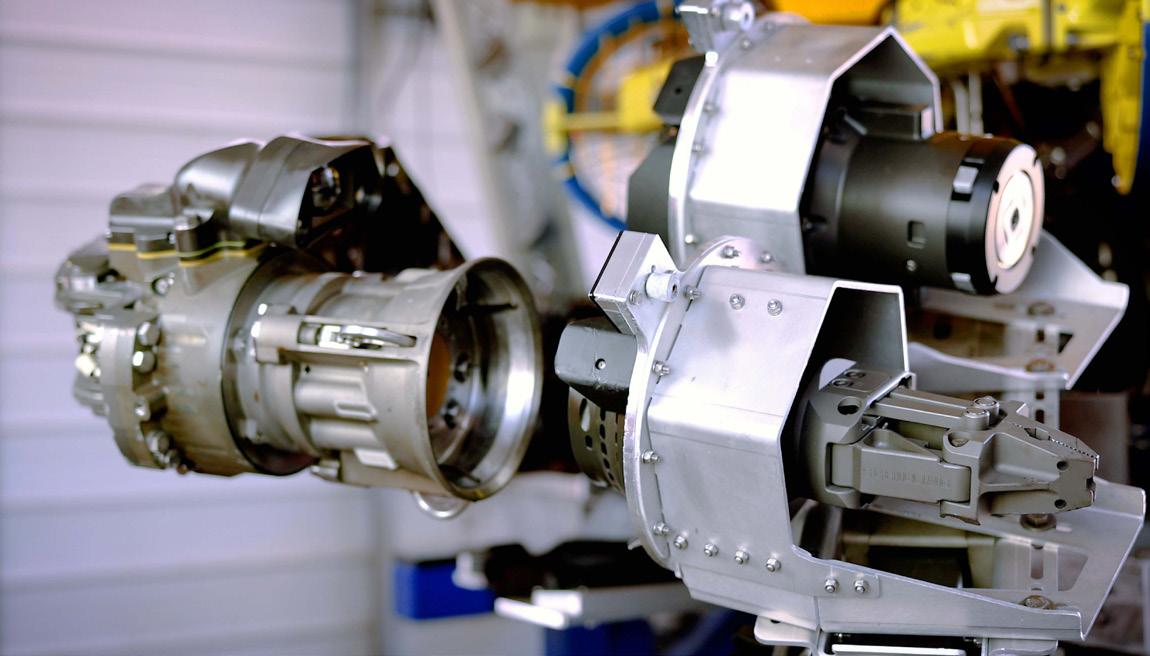
The system uses force compliance and fiducial markers located on the tool holders to positively latch and lock onto the tool.
An additional problem to solve was reducing the risk of damaging the tooling and subsea equipment. On a traditional setup, a pilot individually controls every manipulator joint, using a two-dimensional view. The pilot needs hours of training to become skilled at determining how much force they are applying to subsea structures, how to orient the tool given the two-dimensional camera view, and how to avoid collisions.
Athena helps to solve the control problem with a mode that allows pilots to use a controller to move and adjust the six degrees of freedom of the tool tip. When the pilot tells the manipulator to move the hot stab closer to the receptacle, the control system manages all the manipulator joint positions so the pilot can focus on the hot stab, instead of worry about the location of the manipulator elbow.
With the addition of the wrist camera that doubles as a machine vision camera and a force sensor, the system helps reduce the potential for damage by automatically reducing the force it applies to a level set by the pilot. This corrects any alignment inconsistencies, ensuring optimal interfacing with the subsea equipment.
Conclusion
Subsea interchangeable tooling and advanced controls could enhance today’s operations while supporting the future of remote and autonomous operations, driving change in the subsea industry.
26 | Oilfield Technology March/April 2024
Figure 1. New technologies can help provide consistent and reliable results during subsea operations.
Figure 2. The system wrist engages with the tool holder, storing tooling options and enabling tooling access at the work sites.
Figure 3. Force compliance and fiducial markers located on the tool holders positively latch and lock onto the tool.


Subscribe online at: www.oilfieldtechnology.com/subscribe

Global Publication A global industry requires a global publication


Demands for increased efficiency, economy and transition are driving continuous innovation in offshore oil, gas and subsea technologies. Well services and well intervention are an integral part of the evolution required to transform how the industry will meet the challenges ahead – whether that is about boosting recovery rates, cutting inefficiencies, reducing risk or meeting the demands of decarbonisation.
The cutting edge required is, at its best, built on expertise, experience and the heritage of companies with a history of working in the harshest environments for the most demanding customers.

Partners in success
A successful well intervention partnership is built on a number of key ingredients. The right culture is of course crucial, including respect for the workforce, environment and customers,
28 |

Elisabeth Haram, Odfjell Technology, Norway, outlines how fresh thinking across well intervention and well services could help meet sector challenges in terms of economy, efficiency and transition.
as well as a willingness to embrace new ways of working.
The development of innovative technologies and services are integral to those efforts, particularly when built on a heritage of expertise accumulated and leveraged over many decades. Other positives include flexibility, agility and a willingness to adapt to meet challenges both old and new. Independent operators, seeking to maximise production from existing

infrastructure, are often early adopters of the leading-edge solutions found in well intervention. Their assets are often smaller and/or older fields, and their priority is usually increased recovery at a reduced cost, along with extended life of operations. The target for these companies is often value and efficiency, with a reduced margin for error, but also with the same high standards of safety, environmental protection, and responsible operations.


| 29
Well intervention is key to this philosophy: getting more from less, with low risk and high returns.
Technological innovations that are breaking the mould of how business is done, including more efficient operations to clean blowout preventers (BOPs), proprietary cleaning chemicals and pioneering rigless intervention, are at the heart of this revolution.
BOP cleaning 2.0
The search for efficiencies and enhanced safety in the offshore environment should always be informed by world-class expertise and technologies which enable operational improvements without any compromise to the high standards that are the core of the industry.
BOPs (blowout preventers) are one component that is essential for safe and efficient well operations and benefits from regular debris removal and advanced cleaning solutions, to ensure performance at optimal levels. This has traditionally, however, been onerous and often time consuming.
A revised procedure developed by Odfjell Technology has posted a 50% time reduction in cleaning BOPs without sacrificing results or safety. Trials performed at a major field platform off Norway ran for six months and featured an increased pump rate to significantly improve water flow into the BOP cavities to aid debris removal.
Specifically, annular and variable rams were flushed with two passes, with flowrates increased from 1500 l/min. to 5500 l/min. for the annular, and from 3000 l/min. to 5500 l/min. for flushing the BOP.
The company deployed its RizeRdillo advanced jetting tool, which allows for higher flow rates and enables a larger volume
of fluid with less pump pressure, maximising BOP cleaning efficiencies while reducing operating costs and non-productive time. Time saved during the trial was between 6 – 12 hours with, crucially, zero damage.
The savings of time and money during critical-path activities translate into meaningful gains across efficiency, production and carbon reductions. They are typical of the innovative solutions that will be required as oil and gas tackles the challenges of the shifting economics and carbon imperatives of the energy transition.
Chemical romance
Wellbore cleaning chemicals also have a crucial role to play in the ongoing evolution of well services and the moving landscape of economics and efficiency across the global oil and gas sector.
These high-performance compounds including cleaners and degreasers are designed to quickly and efficiently remove hydrocarbon resides from downhole tubulars, equipment and casings.
In the right hands, wellbore cleaning solutions are non-flammable, non-abrasive and non-caustic formulas that eliminate built-up residue on drilling rigs, pumps and equipment. They are crucial to facilitating efficient fluid displacements during recovery, and will ensure those fluids flow freely, minimising risk while removing the potential for costly and timely shutdowns.
With an in-house offering, rather than supplying through third parties, wellbore cleaning chemicals benefit from streamlined supply chains and all that means in terms of operational control and the associated gains of accelerated delivery and reduced potential downtime.

A competitive edge can be found in a variety of locations. Wellbore cleaning chemicals can unlock opportunities for new business and projects through competitive pricing, providing results at an affordable cost.
As part of a combination of tooling and chemicals, these solutions enhance the efficiency of operations, reducing energy waste and optimising processes that ultimately decrease emissions.
Rethinking rigs
Rigless solutions are another innovation, particularly for the legacy assets which, in the face of shifting societal, governmental and environmental concerns, will often require either evolution of purpose or a shift into late-lifecycle decommissioning.
Existing solutions, whether traditional rigs or existing platform units, carry a high day-rate. They also suffer from a lack of flexibility in terms of availability and responsiveness, with unexpected hurdles and/or delays quickly gobbling up budget and inevitably pushing timelines to the right.
The rigless intervention solution developed for plug and abandonment (P&A) and slot recovery by Odfjell Technology is based on existing components across the company’s service offering and provides set reliability and reduced lead-in times for deployment.
Well control includes an integrated 13 5/8 BOP stack, the BOP control unit, a choke manifold and the trip tank. Tripping and pipe handling (hands-off) extend to a casing jack on the work deck, a vertical pipehandling system for tubular transfer, innovative
30 | Oilfield Technology March/April 2024
Figure 1. Advanced jetting tool.
Figure 2. Rigless P&A unit.
pipe storage ‘cassette’ systems and a small cherry picker for general utility and handling purposes.
A small footprint offers streamlined logistics, and clears the way for installation in the shortest possible period of time with the fewest number of lifts. From deployment through testing and into operations, the timeline has been optimised to enable flexibility and responsiveness.
The rigless approach has additional benefits – allowing for offline data collection on barrier status, for instance, or enabling development, testing and qualification of other next-generation P&A technologies. This is about cost-effective alternatives to the more expensive and less flexible options represented by traditional offshore capabilities.
The rigless concept fits alongside existing oil and gas capabilities, and parallel innovations including modular rigs. Deployment will free traditional units to perform the heavier lifting jobs, to drill new wells, and to avoid downtime on the back of increased visibility about barrier status.
The results
For the rigless concept, trials at an onshore geothermal project earlier this year included jetting technology that fractured subsurface geology every 5 –7 m between 270 – 70 m deep. An underground storage for district heat was created between an injector and a series of producer wells, with good results across the network.
On BOPs, subsequent to the results of the previous trials, the RizeRdillo advanced jetting tool cleared post-completion debris from a problematic component deployed by a harsh environment sixth generation rig, saving a total of 33 hours and
an estimated US$773 000. The solution, including offset jetting nozzles for increased penetration, optional lower bull nose or pin-down connection, and an optimised flow path for removal of debris, was extended to the nine subsequent wells.
The combination produces savings economically by sidestepping the need for more expensive interventions or workovers, and in terms of efficiencies, by optimising production rates and enhanced hydrocarbon recovery.
Cutting-edge commitment
The oil and gas sector continues to evolve at breakneck speed, with innovation and expanded horizons driving progress in every corner of the globe but especially in the offshore and subsea segments.
Technology is the engine room of that change, and companies understand the potential and the challenges inherent in the pursuit of real-world results measured by economics, production and the energy transition.
There is no secret formula for success. Instead what is required is a willingness to embrace next-generation solutions, putting expertise and experience in the service of innovations that anticipate the demands of operators and other customers.
In-house wellbore chemicals that unlock new avenues, a quantum leap in BOP cleaning, and rigless and modular concepts across well intervention, are the type of offshore services that contribute to safe, decarbonised and world-leading operations.
It is the combination of execution and evolution that makes all the difference: more efficient well intervention products and services create better projects which are more efficient, more sustainable, and have a better return on investment.


Keep up to date with us to hear the latest in upstream oil and gas news Stay informed www.oilfieldtechnology.com


32 |

| 33
re-exposed formation. Delivering these chemicals in separate stages reduces the risk of incompatibility. However, this increases the job’s complexity, requiring more stages, chemical volume, and time, equating to higher operational costs.
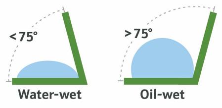
Figure 1. Surfactants change the native oil-wet rock surface to water-wet, facilitating oil mobilisation. This wettability alteration is quantified by measuring the change in contact angle between a liquid drop and oil-coated surface. Ideal contact angles for water-wet surfaces are <75°.
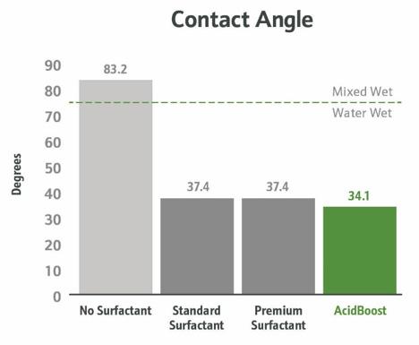
Figure 2. A comparison of the contact angles reveals that the biosurfactant-based product has equivalent water-wetting capacity compared to the synthetic surfactants used in the laboratory tests.
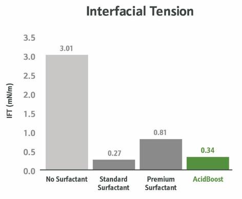
Figure 3. Surfactants are used to reduce the IFT between water and oil, which lowers the resistance to oil flow in the presence of water. Test results demonstrate that the biosurfactant-based product’s ability to reduce IFT was equivalent to conventional surfactants.
Like the drilling permitting process, CalGEM has been slow in signing off on larger well stimulation jobs due to environmental concerns of pumping large volumes of acid, solvent and conventional surfactants. Costs for these chemicals have also risen in recent years. As a result, some California operators are performing large-scale acid jobs less frequently, even in the face of declining annual production rates. They are faced with the challenge of finding new ways to squeeze more oil production out of each acidising job they perform. For some, the solution involves biosurfactants.
Real world impact
The power of biosurfactants
Surfactants have traditionally played a crucial role in optimising oil production. While conventional surfactants are sourced from non-renewable, petroleum-based materials, bio-based surfactants can be partly or wholly derived from biological sources. Biosurfactants are a premium subset of bio-based surfactants that are 100% derived from renewable raw materials. Because of this, biosurfactants feature complex molecules with more active sites and multifunctional properties. They have outperformed conventional surfactants in a variety of oil and gas applications. For instance, Locus Bio-Energy’s wellbore remediation treatment allows operators to replace multi-stage solvent packages with a single acid additive. The biosurfactant-based microemulsion is effective as both a surfactant and a detergent at low concentrations. It helps streamline the lengthy process of ensuring chemical compatibility with acids and solvents in the acidising treatment, while also improving performance.
Biosurfactant-based products are currently emerging as a cost-effective solution for acidising operations in California’s major producing basins. Its increased use in the region is in part due to the joint testing efforts of an acidising services company and specialty chemical supplier. Outside of the state, biosurfactant technologies have been in use for years, with applications specific to acidising in the Appalachian, Williston and Permian basins. For example, a low-producing well in the Northeast US more than doubled its prodcution per day after one acidising treatment containing AcidBoost. The operator followed the single-stage acid job with another biosurfactant-based product, AssurEOR STIM, an enhanced oil recovery product recently certified by SGS to improve oil production by 10 – 45%, while reducing carbon intensity by 7 – 20%. This combined treatment led to substantially higher and prolonged production rates for longer times compared to the operator’s orginal acid programme.
Case study
Encouraged by the positive results in other regions, Cal Coast Acidizing Services saw potential to offer improved efficiency and economics for California acidising jobs. The company then approached Locus Bio-Energy for recommendations on incorporating biosurfactants into its chemical programme, particularly a single-stage deployment of acid, solvent, surfactant and anti-sludge agents.
Laboratory testing and
results
In response, the biosurfactant scientists designed the laboratory test protocol to highlight two of the biosurfactants’ abilities: promoting oil flow and cleaning oil from an acid-soluble material. Testing commenced with two test surfactants commonly used in field acidising treatments. One was a standard surfactant similar to an
34 | Oilfield Technology March/April 2024
alcohol ethoxylate, and the other was a premium surfactant similar to a microemulsion or nanosurfactant. Details on their acid blend formulations were also provided for evaluation.
Replacing surfactants
The initial round of testing was focused on demonstrating how AcidBoost reduces the need for additional surfactants.
The biosurfactant-based product was compared to the standard and premium surfactants on abilities to alter wettability (from oil-wet to water-wet) and reduce interfacial tension.
Ì Contact angle: wettability is the force of attraction between a solid (reservoir rock) and a liquid (crude oil). Surfactants change the native oil-wet (or ‘oil loving’) rock surface to water-wet (or ‘water loving’). This change in wettability allows water to displace crude oil on the surface of the rock. In the laboratory, contact angles are used to measure changes in surface wettability. Ideal contact angles for a water-wet surface are <75° (Figure 1).
To determine AcidBoost’s water-wetting ability, the contact angle was measured using the sessile drop technique on a drop shape analyser. Drops of surfactant solutions were deposited on a mixed wet substrate coated in crude oil. A comparison of the contact angles (Figure 2) revealved that the biosurfactant product had equivalent water-wetting capacity as the conventional surfactants.
Ì Interfacial tension (IFT): The scientists then tested for IFT, which measures the force of attraction between two different liquids. Surfactants are used to reduce the IFT between water and oil, which lowers the resistance to oil flow in the presence of water. The IFT between oil and 15% HCl solutions, with and without surfactant, was measured on a spinning drop tensiometer. The results (Figure 3) showed that the biosurfactant’s ability to reduce IFT was equivalent to other surfactants.
The combined contact angle and IFT results indicate that biosurfactant technology can eliminate the need for additional surfactant in acid remediation.
Replacing solvents
The next objective was to show that biosurfactant-based products could also replace the need for additional solvents. A series of base formulations was prepared according to the desired blend details. All incumbent base formulations were made with 15% HCl, the incumbent surfactants, and xylene as the solvent. The biosurfactant-based blend only contained 15% HCl and AcidBoost, devoid of additional surfactant or solvent.
Ì Detergency: the final set of laboratory tests measured the degree of detergency, or oil removal, of the biosurfactant formulation. Removing oil from the rock face is critical to ensure that the acid can contact the carbonate or other acid-soluble solid. In traditional acidising formulations, solvents are typically used to remove the bulk of oil from the rock, followed by the surfactant to alter the wettability at the oil/rock interface, remove more oil, and leave a cleaner surface for the acid to do its job. A surfactant formulation with poor detergency leaves more oil behind, which lowers the efficiency of the entire acidising job.
Glass test vials containing oil-saturated carbonate rock samples were prepared with the various test formulations. The reaction was allowed to equilibrate for one hour at room temperature and static conditions. The vials were then laid on their sides and observed through the bottom (Figure 4).
The biosurfactant treatment alone demonstrated better detergency and surfactant properties than the combined solvent/surfactant test formulations. AcidBoost’s detergency power removed oil from the rock, optimising the surface for acidising. Moreover, its demulsification and wettability alteration functionalities left the system emulsion-free and in a water-wet state.
Cal Coast also conducted its own laboratory studies on the biosurfactant’s detergency performance compared to straight solvent alone. These tests, coupled with results from Locus Bio-Energy, verified that biosurfactant-based products could deliver comparable surfactant and solvent performance at lower doses compared to the incumbent chemistries. In the field, this
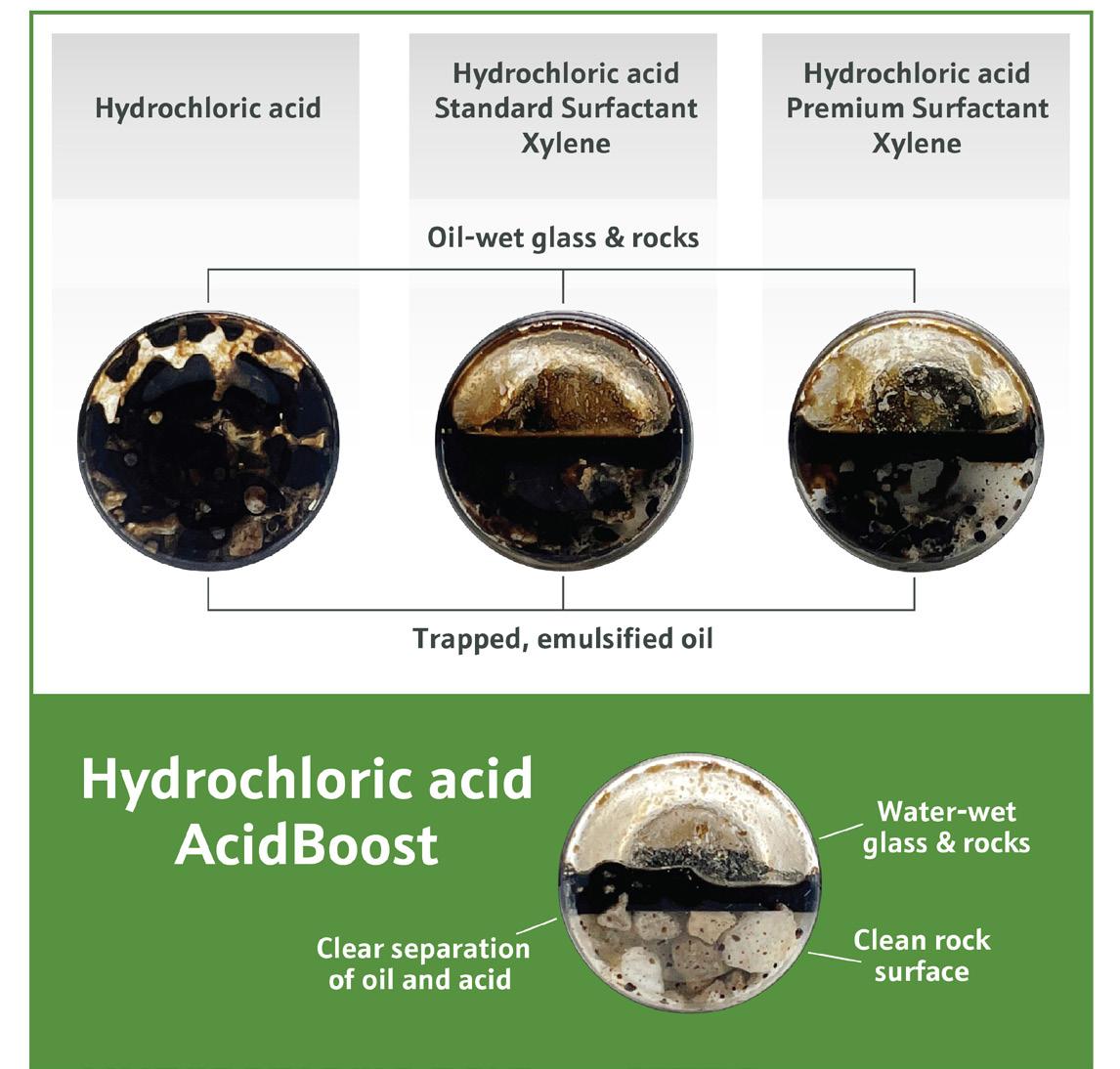
Figure 4. Although the biosurfactant treatment did not contain any additional solvent and surfactant, it demonstrated superior detergency and surfactant properties compared to the combined solvent/surfactant test formulations.
Ancillary Chemicals
FOUR TOTES
Solvent, Surfactant, Anti-sludge
Figure 5. In the two-stage plug and packer case history, the incumbent formulation required 1346 gal of ancillary chemicals, totaling four totes. This was reduced to a single tote, or 225 gal, since using the single biosurfactant-based additive eliminated need for additional solvent, surfactant and anti-sludge.
March/April 2024 Oilfield Technology | 35
ONE TOTE AcidBoost
translates to better penetration and reactivity for the acid treatment, ultimately delivering more effective remediation for improved production rates.
Field applications and results
Based on the lab studies and AcidBoost’s performance in other regions, the biosurfactant formulation was trialled in two applications: a backside producer dump and a two-stage plug and packer. In these treatment examples, the formulation successfully replaced all ancillary chemicals (solvent, surfactant and anti-sludge) with the acid content remaining constant.
Ì Backside producer dump: a producing well was shut in, followed by pumping the biosurfactant-based formulation with acid down the backside of the casing to the upper zone of the slotted liner, and then following with a predetermined volume of water to displace the acidising treatment. In this application, just 10 gal of AcidBoost was used, compared to 60 gal of ancillary chemistries in the incumbent formulation.
Ì Two-stage plug and packer: the operator set a packer to isolate the acidising zone of interest followed by pumping the treatment containing AcidBoost. Once the acidising formulation was displaced with water, the packer was moved to another acidising zone and the process was repeated. By using highly effective biosurfactants at low dosage rates, the amount of ancillary chemicals required went from 1346 gal to 225 gal. The number of totes required on location reduced from four to one (Figure 5).
Replacing anti-sludge agents
The biosurfactant-based formulations for the applications were effective, even though they used less chemicals than

prior treatments. In both examples, volumes of non-acid chemistries decreased by >80%, including the elimination of anti-sludge agents. The prior field formulation required an anti-sludging agent to treat the iron sludge created during acidising. Although AcidBoost does not contain traditional anti-sludge agents, its combination of chemistries reduces the amount of sludge generated, thus reducing the need for the anti-sludge or other iron control agents in some applications.
The amount of biosurfactant-based treatment used in the field was three times lower than the dosage tested in the lab. Even at this lower field dosage, the formulation delivered measurable performance and production gains.
Paving the future for California’s oilfields
Collaborative initiatives of this nature are vital to propel the oil and gas industry forward through the energy transition. Given the diversity of reservoir conditions, open communication is key to facilitate cutting-edge technologies effectively and rapidly. In this way, tailored solutions such as biosurfactants are increasingly being integrated to create a more productive and sustainable future for California’s operators and beyond.
References
1. www.reuters.com/business/energy/california-new-oil-well-approvals-havenearly-ground-halt-data-show-2023-07-13/
2. www.kqed.org/news/11940704/california-oil-industry-brace-for-big-moneybattle-over-rule-limiting-drilling-near-schools-and-homes
3. www.gov.ca.gov/2021/04/23/governor-newsom-takes-action-to-phase-outoil-extraction-in-california/#:~:text=SACRAMENTO%20%E2%80%93%20 Governor%20Gavin%20Newsom%20today,fracking%E2%80%9D)%20by%20 January%202024.


Receive the latest issue of Oilfield Technology straight to your inbox Never miss an issue Join our free newsletter today: www.oilfieldtechnology.com/newsletter/

Edward Owen, Welltec, Denmark, discusses how hardware milling technology is making waves in subsea intervention.
When a novel technology becomes accessible to the oilfield interventions segment, developers are often tempted to opt for less challenging operations in order to gradually establish a successful track record and build a reputation. In 2022, the results of an extensive testing period encouraged Welltec to launch the Well Miller® CVF (Continuous Variable Force) by executing two intricate subsea hardware milling operations within days of one another, on separate continents. An electronics platform is integrated with a combination of hardware milling services and a linear actuation device capable of applying up to 5000 lbs of force in increments of 100 lbs.
Planning and execution of the two operations to resolve issues with assets operated by TotalEnergies went ahead in parallel, with the complexities of each job requiring solutions including custom mill bits to head-up the toolstring. Rigging up and operating almost simultaneously, success was confirmed in early June 2023.
In both of the following cases, the CVF milling technology and its downhole CNC-like ability was used to address challenges with precision, providing cost savings.
IN AT THE DEEP END
| 37
North Sea case study
A stellite-coated flow target
TotalEnergies was facing a significant challenge with a subsea Christmas tree in the North Sea. Downhole access was being blocked by a flow target lying in an upside-down position – an 8 in. circular disc that was screwed into the underside of the lower crown plug but had fallen a few feet down onto a shoulder restriction, most likely due to erosion of the threaded element. This situation was preventing the continuation of plug and abandonment
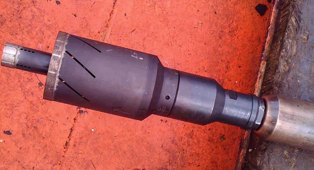
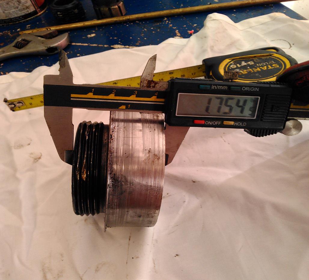
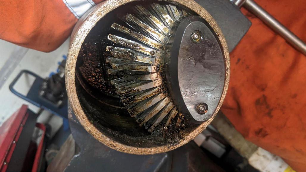
activities, and the inner diameter going through the Christmas tree made it impossible to fish the flow target, meaning that the only solution was to mill the highly resistant fixture.
Furthermore, because the flow target had flipped 180°, this meant that any intervention tool coming in would meet the stellite-coated underside first. To compound the issue, the operation would also need to be carried out from a semi-submersible rig, creating the need for an accurate solution that could deliver precise and controlled weight on bit (WOB).
While high-pressure water jetting technology has worked for similar applications in the past, running high-pressure hoses without prior access was not an option. Although coiled tubing or drillpipe applications may have successfully destroyed the flow target, these would have undoubtedly caused damage elsewhere. Something with more ‘surgical’ accuracy was required.
The solution
Prior to the operation itself, extensive testing led to the development of a custom-made two-stage bit (pilot and core) to ensure the retention of the milled-out coupon. A specially designed sleeve was first set above the flow target, and this ensured that the CVF milling technology engaged off-centre, preventing the flow target from simply rotating upon contact.
The stroker section of the toolstring provided a self-anchoring bi-directional axial piston (anchored above the Christmas tree) with a shearable spacer bar between the anchor point and the mill bit, i.e. shearable across the subsea XT shear rams.
The two-stage bit consisted of a smaller pilot section tipped with metal matrix compound (MMC), which was diamond-encrusted, to perform the milling action. In addition, the pilot section included fins along the side that expanded and therefore trapped the coupon after milling. This two-stage approach was the safest way to capture the whole coupon and avoid a ‘lost in hole’ scenario. Dynamic WOB was a crucial factor for success, with the optimal performance of the two-stage bit depending on variability to correspond to the size of the stage in use i.e. lower WOB for the pilot, which incidentally provides higher pounds per square inch due to the smaller contact area, before increasing WOB for the larger core bit area.
After the pilot section of the mill bit breached the flow target, dynamic WOB was applied in increments of 100 lbs with up to 5000 lbs available, and surface readout (SRO) data enabling the precise monitoring of the stroker extension. Over two runs, and milling time of ~10hrs, a 4.4 in. hole was created through the stellite-coated stainless-steel flow target and the coupon was recovered back to the surface.
This allowed the setting of a 3 in. ID conduit sleeve to ensure safe access for subsequent runs into the well with a deep-set plug, after which a mechanical cutting tool was utilised to cut the 4.5 in. completion.
Offshore Congo case study
An incoloy gate valve
Another downhole hardware issue was presenting an equally complex challenge in Congo, where the necessary replacement of a subsea Christmas tree was being prevented by a gate valve that was stuck in a partially open position, with only 55% of the wellbore diameter accessible.
With added difficulty from the valve being made of a 3 in. thick plate of high-strength Incoloy 925, there was a demand for a robust but precise solution capable of milling through while
38 | Oilfield Technology March/April 2024
Figure 1. Case 1: custom-made bit with a two stage pilot and core.
Figure 2. Case 1: milled coupon from flow target, recovered to the surface.
Figure 3. Case 2: custom bit design incorporating a mechanism to securely lock into the milled section, complemented by a coupon-catching mechanism to retain the milled gate valve.


Visit our website today www.worldpipelines.com
Pipeline Industry Website
The home for the latest pipeline news, analysis, comment and events
simultaneously ensuring the milled section could be retrieved to the surface and not lost downhole.
Faced with the possibility of having to arrange for a full workover rig, an alternative plan was developed, utilising the CVF milling technology, and in terms of cost-savings this would enable the operation to be carried out from a riserless light well intervention (RLWI) vessel.
The
solution
The operation was split into two main phases: design, and execution.
Design
The design phase of the operation was initiated with the development of a custom locating bit designed to precisely match the profile of the partially open gate valve. This custom-manufactured ‘key’ was essential for facilitating the mill bit’s unrestricted functionality. The design incorporated a mechanism to securely lock into the milled section, complemented by a coupon-catching mechanism to retain the milled gate valve.
To validate the design, multiple replicas of the stuck valve were manufactured and sent for testing due to the complexity of the operation, with trials including horizontal and vertical milling operations. These tests ensured recovery of the milled section, and this process led to the manufacture of a unique metal matrix compound (MMC) bit with an eccentric spear and a spring-loaded locating shoe.
The result was a fully controllable toolstring with bi-directional force capabilities, allowing it to be pulled free from a stuck scenario on the same run.
Execution
The design features facilitated the ability to pull the toolstring free in the event of a stall, employing dynamic WOB for an automatic milling sequence. The toolstring was securely anchored within a qualified area to prevent damage to the subsea stack. CVF milling technology provided dynamic WOB and piston movement indications, and continuous feedback. Once the custom ‘key’ landed in the precise position for valve milling, real-time monitoring of multiple parameters, including WOB and rate of penetration, guided the milling process.
Milling began at 600 lbs WOB and increased to 1100 lbs in increments of 100 lbs. Finally, surface inspection confirmed coupon recovery within the custom-made catching mechanism, and the gate valve had been successfully milled through in 17 hr.
Conclusion
Highly resistant components made from incoloy or coated with stellite are a necessary feature of subsea well design, ensuring integrity and durability. In turn, this creates the need for equally or more capable hardware milling solutions like CVF technology, providing optimised intervention through powerful, precise, and controlled force.
CVF milling is a new method derived from a combination of existing services, resulting in a new solution that has helped enhance the standard of hardware milling. For both of the featured case stories, there was no realistic alternative available at the time; neither would have been possible in the same manner without the dynamic aspect, essentially providing an automated milling service.
40 | Oilfield Technology March/April 2024
Never miss an issue! Go to: www.oilfieldtechnology.com/magazine Advertiser Index ABACO DRILLING TECHNOLOGIES CRC EVANS GASTECH EXHIBITION AND CONFERENCE OILFIELD TECHNOLOGY OMNETICS CONNECTOR CORP. PACCAR WINCH 04 02 19 27, 31, 36, OBC 23 07 PALLADIAN ENERGY PODCAST VAREL ENERGY SOLUTIONS VINK CHEMICALS WILD WELL CONTROL WORLD PIPELINES IBC IFC OFC, 09 13 39


We hope you enjoyed the latest issue of Oilfield Technology magazine. For more information on advertising opportunities please contact: For any editorial enquiries please contact: www.oilfieldtechnology.com/magazine chris.lethbridge@oilfieldtechnology.com daniel.farr@oilfieldtechnology.com emily.thomas@oilfieldtechnology.com
