14 minute read
Combining sensor powers for autonomous vehicles

from VTE March 2020
by Possprint
A camera that registers a blank space on each image probably has a faulty design. If you compare the human eye with a camera, then the exact same thing happens when seeing. At the place where the optic nerve exits the retina, there are no receptors that record the light stimuli from which an image forms in the brain. This part of the eye is referred to as the blind spot. However, it does not disrupt anything because the information from the surrounding receptors on the retina and, especially, the visual impressions from the other eye, offset the missing image points. At the same time, two eyes next to one another ensure that we can see spatial depth, a major requirement in estimating distances. Expressed in technological terms, the data from two sensors merge or fuse to become a more complete image with more information. Developers of automated driving functions also use this principle. Very different sensors are needed so that a driverless vehicle can also unequivocally comprehend every traffic situation even in unfavourable lighting and weather conditions. Cameras, radar and lidar sensors each have their special advantages. If intelligently bundled, they allow for a sweeping and detailed 360-degree view. Cameras are indispensable for object detection. They supply the vehicle with the necessary information by using artificial intelligence to detect objects, such as pedestrians or garbage bins, along the side of the road. Furthermore, the camera’s greatest strength is that it can measure angles precisely. This allows the vehicle to recognize early on whether an approaching vehicle will turn. If city transport requires a wide angle of vision to record pedestrians and traffic, a long range of up to 300 meters and a narrow angle of vision are necessary on highways. However, cameras not only monitor the exterior surroundings of the vehicle, they also keep an eye on the driver and passengers inside the vehicle. For example, they can recognize not only whether the driver is distracted or tired, but also which seating positions the passengers select. This knowledge represents a major safety plus because, in case an accident occurs, the seat belt and airbag functions adapt accordingly. Unlike cameras that passively record image information, radar systems are an active technology. These sensors emit electromagnetic waves and receive the “echo” that is reflected back from the surrounding objects. Radar sensors can therefore determine, especially, the distance and the relative speed of these objects with a high level of accuracy. That makes them ideal for maintaining distances, issuing collision warnings or for emergency brake assist systems. Another decisive benefit of radar sensors compared with optical systems, is that they function regardless of weather, light or visibility conditions because they use radio waves. That makes them an important component in the sensor set.
The merged information from radar, lidar and the most diverse range of cameras is already enabling vehicles to identify and handle even the most complex traffic situations.
Lidar sensors also apply the echo principle however, they use laser pulses instead of radio waves. That’s why they record distances and relative speeds equally as well as radar but recognize objects and angles with a much higher level of accuracy. This is also a reason why they oversee complex traffic situations in the dark very well. Unlike cameras and radar sensors, the angle of view is not critical because lidar sensors record the 360-degree environment of the vehicle. High-resolution 3D solid state lidar sensors also display pedestrians and smaller objects three dimensionally. This is very important for automation as of level 4. The solid-state technology is considerably more robust than previous solutions due to the lack of moving components. To merge the sensor information from the lidar, radar and camera systems to create one complete picture, a “brain” is also needed. Once vehicles are equipped with this artificial brain, drivers will soon be able to close their eyes or do something else and leave the driving up to their autonomous vehicles.

The Study of Optimization of Sliding Door Effect
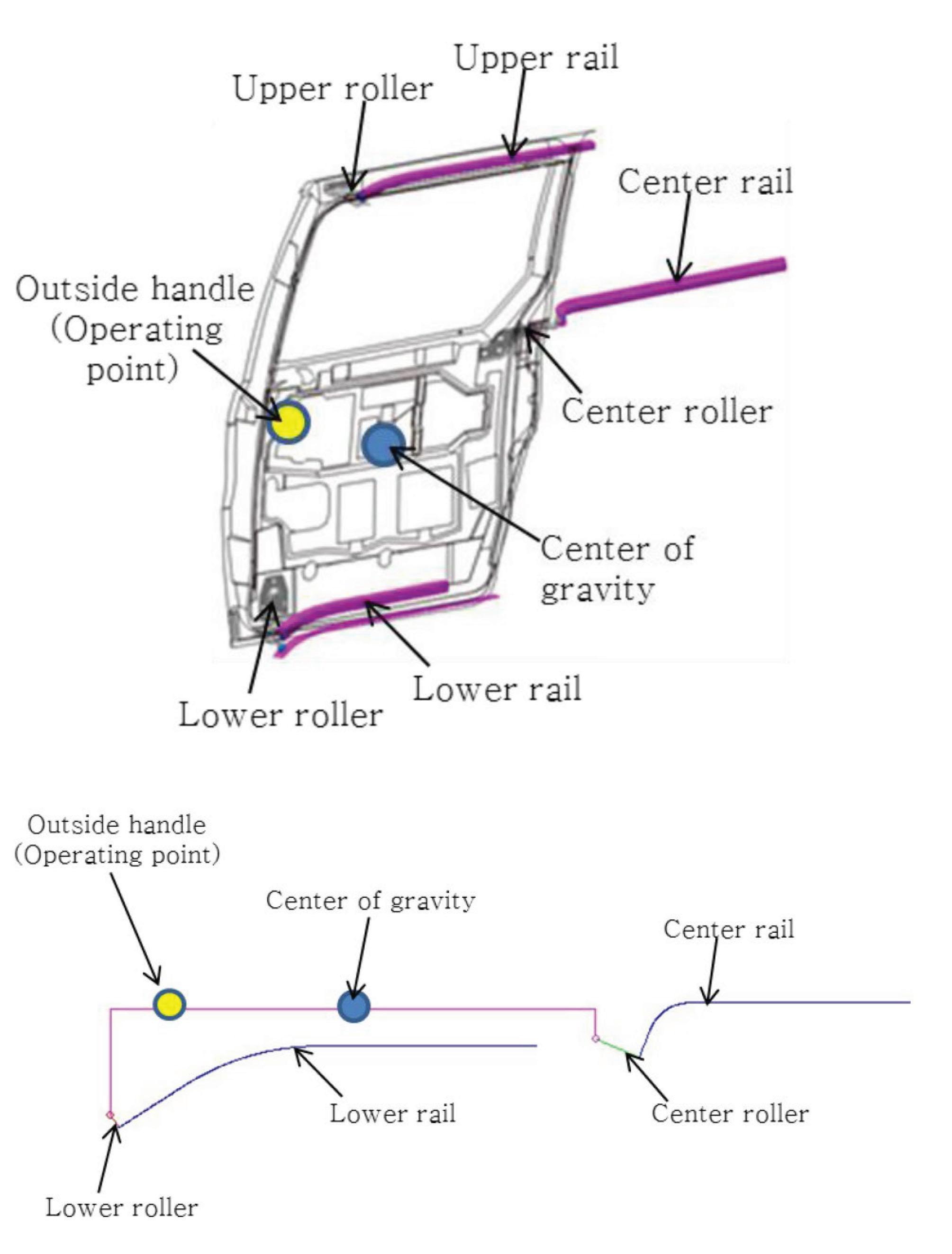
FIGURE 1: The mechanism of sliding door
Introduction The way we look at life is changing. Recently, the proportion of spending time for leisure with the family is expending. As a result of these changes, the automobile is not only transportation, but an important means of increasing the value of a customer’s life. As a result of these changes, demand for MPV vehicles for enjoying leisure activities of family units is increasing, and interest in sliding doors characteristic of MPV vehicles is naturally increasing. In this paper, we analyze the operating factors of the sliding doors and set up the optimal layout for the development of sliding doors that can be easily opened and closed by any family member including children, women or the elderly.

Subject 2.1. Sliding Door Mechanism As shown in Fig. 1, the sliding door operating mechanism is Sliding the open/close operation of the sliding door using the outside handle is attached to the sliding door and the door is translated in the same time that a rotational motion along the rail. Door operating mechanism is; That is, depending on the layout of the three rails and three rollers a locus of the sliding doors is changed thus the force that is the operating force to open or close the sliding doors is changed. 2.2. Operating Force Factor Analysis Parts that affect the sliding door operating force include door panel, outside handle, center roller, center rail, lower roller, and lower rail. The analysis of each component as a factor Table.1 and Fig. 3 A sliding door operating force major factor
ABSTRACT A sliding door system is one of the vehicle door types, which is generally applied to the MPVs. The sliding door contains three rails (an upper, a centre, and lower rail), which are mounted on body structure, and three rollers (the upper roller, the centre roller, lower roller), which are mounted on the sliding door side. The system is different from a swing door, rotated by hinge axis. To set up sliding door layout for better performance, predicting the operating force is one of the main factors, But the door moving trace is on threedimensions; hard to calculate and predict. So in this study, the objective is to analyze the impact between the main factors affecting the performance of the closing and opening performance of the sliding door through the study of formula and a layout scheme for ensuring the best operating performance of sliding doors.
Citation: Yun, H.I. and Yim, C.S., “The Study of Optimization of Sliding Door Effect,” SAE Technical Paper 2019-01-1425, 2019, doi:10.4271/2019-01-1425.
in Table.1 were classified into three types as below. • Design factor Center of gravity, handle hinge axis, handle point of action • Properties associated factors Bearing Stop/Motion Friction Coefficient, Spring Constant • Design factor Roller hinge shaft, rod/guide bearing point, Curve R, rail angle Design properties and related factors were conducted to optimize the operating force by a factor because it is treated as a constant

FIGURE 2: Moving motion of the door

and fixed according to the design parameters as vehicle variables. 2.3 Sliding Door Trajectory Point Setting In order to know the instantaneous operating force of the handle at any moment for operating the sliding door, the force acting on the handle which makes the sum of the force and moment generated by the frictional force, vertical drag, and gravity acting on the door to ‘0’ should be obtained. To do this, it is necessary to find the behavior including the position and the angle of the accurate instantaneous sliding door. In order to calculate the position of the sliding door, it is necessary to set three points in the sliding door. The point of the hinge axis of the roller whose absolute position with respect to the sliding door does not change according to the sliding door behavior (rotational motion + translational motion) is used. In other words, the behavior of the door is analyzed along three loci using two points on the center roller hinge axis and the lower roller hinge axis, and the operating force is calculated from the degree of freedom analysis at each position. (Fig. 4) 2.4. Sliding Door Operation Force Operating force is the force required to move the door at a particular moment. Through KINEMATICS, TRACE (movement of 3 points when opening the sliding door) of the abovementioned 3 points (1 point on the centre roller hinge axis, 2 points on the lower roller hinge axis) can be obtained through Catia. ] Based on this, the frictional force acting on the rail and the direction of the vertical drag can be obtained. If these directions are fixed and only the magnitude of the force is set as a variable, the force to be obtained through the equation is; 1. Lower rail: Guide bearing normal force,
load bearing normal force 2. Centre rail: Guide bearing normal force, load bearing normal force 3. Upper rail: Guide bearing normal force 4. Handle force (The frictional force is naturally obtained through the normal force). There are a total of six unknowns. At this time, six equations of motion are obtained through six degrees of freedom constraint, and the magnitude of force in each situation can be obtained. The direction of the frictional force in each rail is defined as the direction from the current point to the previous point, the direction of the guide bearing perpendicular to the xy plane at the current point, and the direction of the load bearing vertical force perpendicular to the rail on the zx plane at the current point. The variable definition is as follows. 1. N LG = Lower roller guide bearing’s normal force 2. N LL = Lower roller guide load bearing’s normal force 3. N CG = Center roller guide bearings’ normal force 4. N CL = Center roller load bearings’ normal force 5. N U = Upper roller guide bearings’ normal force 6. H = Operation force of handle The dependent variable, frictional force, is defined as follows. 1) f U = Friction factor of upper roller bearing 2) f C = Friction factor of center roller bearing 3) f L = Friction factor of lower roller bearing Let the above six variables (Separated by scalar value only) x_1~x_6, N_LG be a direction vector with no magnitude. The equation of motion is as follows; TABLE 2: Compare calculated and measured value


FIGURE 4: Sliding door datum point setting

Define the front term of x_1 as a_11, the front term of x_2 as a_12, and the front term of x 1 of F_y as a_21, the moment equation is as follows;

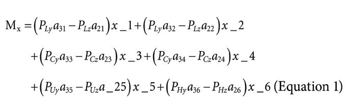
FIGURE 5: Diagram of the vehicle
P_Ly is the y value of the relative position of the lower rail point with respect to the center of gravity of the door. Likewise, we can obtain six momentary linear equations for x_1 ~ x_6 by obtaining moments in the y and z directions, Table 2 compares the actual values of the vehicle with the calculated values. Put all the points obtained through TRACE in turn, you can obtain the operating force at all moments.

FIGURE 7: Operating force diagram by angle change
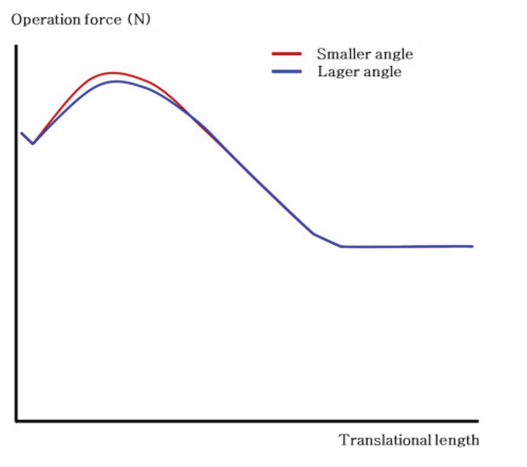
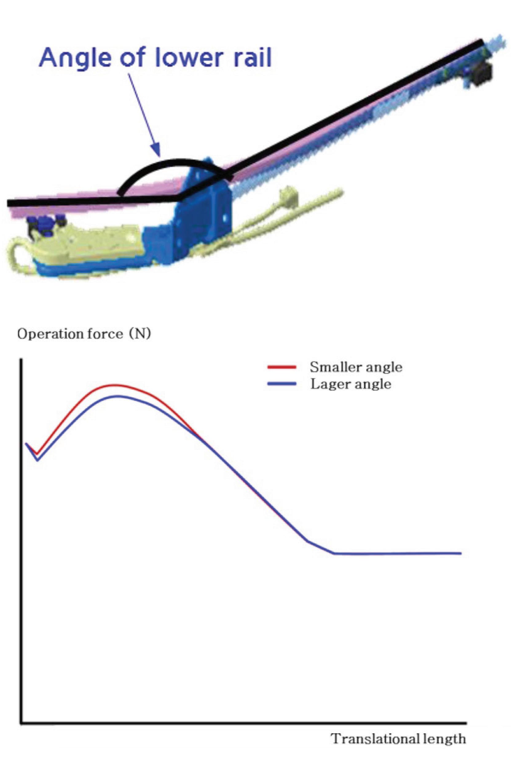
Based on this, you can obtain the operating force diagram for the sliding door opening as shown in Fig. 5 2.5 Study on Sliding Door Operating Force Optimization By analyzing the impact of the design parameters associated with a sliding door operating force mentioned in Section 2.2, each tries to derive a sliding door operating force optimization. 2.5.1 . Analysis of the Influence of Center Rail Angle The angle of the centre rail is typically set at certain degrees. If it is set under minimum degrees, there is a high risk of a section shrinkage problem. When the sliding door is opened at the initial opening of over widen angle, there is a problem of interference with the vehicle structure. The operating force diagram obtained by changing only the center rail angle under the same conditions is shown if Fig. 7; As shown in Fig. 7, the larger the angle of the center rail, the smaller the ratio of the maximum operating force to the initial operating force. That is, when the maximum operating force value is upper limit angle relative to lower angle, there is an operating force improvement of about 5%. 2.5.2. Analysis of the Influence of Lower Rail Angle Change the lower rail angle under the same conditions and draw the operating force diagram as shown in Fig. 8 As the lower rail angle increases the same as the center rail angle, the sliding door maximum operating force value decreases. However, as the angle increases, there is a possibility of interference with the vehicle body when the sliding door is opened. Therefore, it is advantageous for the operating force to increase the lower rail angle while securing the gap with the surrounding components. 2.5.3. Analysis of the Influence of Center Roller Arm Length For the analysis of the influence between the center roller arm length and the operating force, the operating force curve was obtained by changing the arm length only under the same conditions. As shown in Fig. 9, the longer the cente roller arm length, the larger the initial operating force magnitude and the maximum operating force generation interval is changed to the initial value of the sliding door operation. That is, in order to improve the sliding door operating force, the arm length of the center roller must be set to a minimum. It is necessary to set the minimum length of the centew roller arm having the gap on the locus of the sliding door since the gap between the center roller and the vehicle body cannot be secured when the length of the center roller is shorter. 2.5.4. Analysis of Influence of Distance from Lower Roller Guide Bearing to Hinge Axis The operating force diagram was obtained by changing only the arm length under the same conditions for the analysis of the influence between the distance from the lower roller guide bearing to the hinge shaft and the sliding door operating force. As shown in Fig. 10, the longer the distance from the lower roller guide bearing to the hinge axis, the larger the initial operating force magnitude, similar to the influence of the center roller arm length, and the maximum operating force generating interval is changed to the initial stage of sliding door operation. That is, to improve the
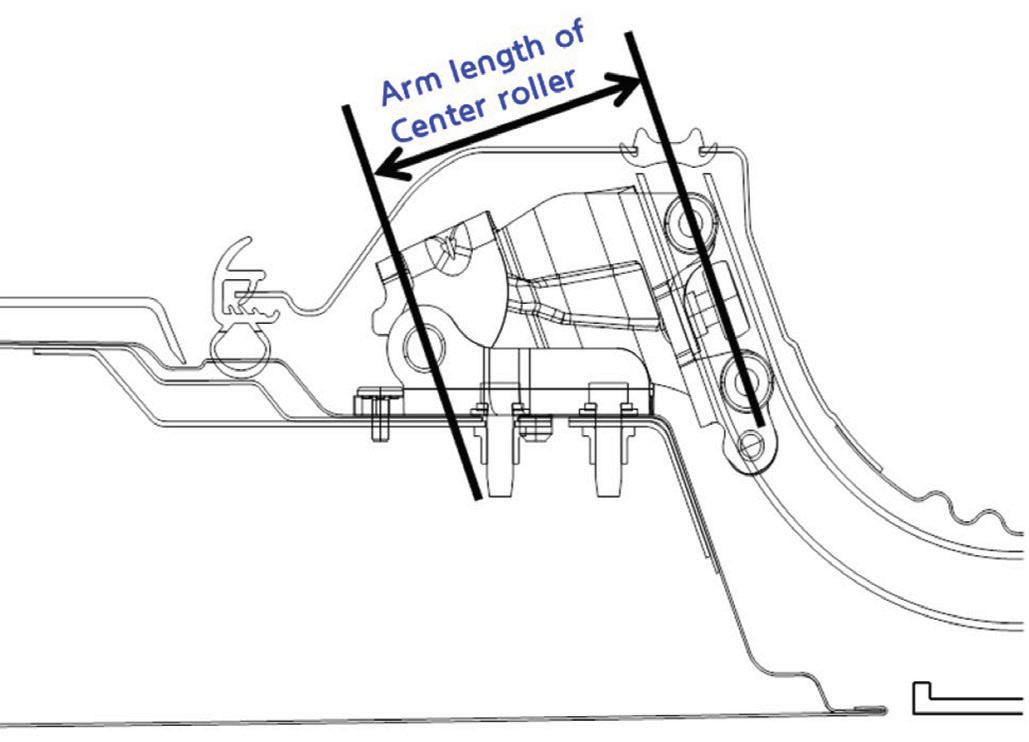
FIGURE 9: Center roller arm length and Operating force by center roller arm length

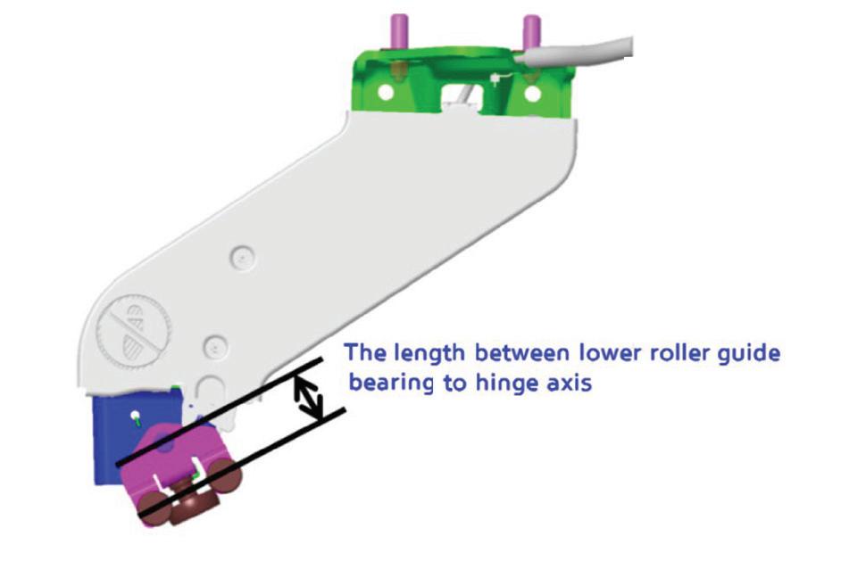

FIGURE 11:Radial value of center rail and operating force diagram by center rail radial value
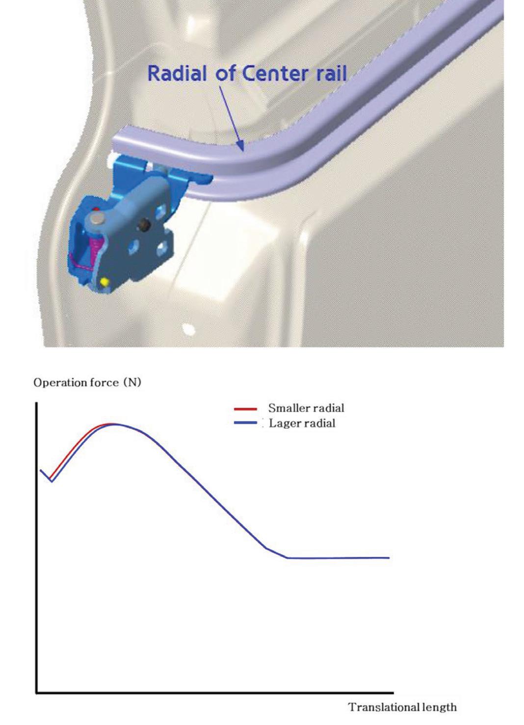
sliding door operating force, the length between the lower roller guide bearing and the hinge axis must be set to a minimum. 2.5.5. Analysis of Influence of Radial Value of Centre Rail In order to analyze the influence between the centre rail radial value and the operating force, the operating force curve was obtained by changing only the radial value of the center rail under the same condition. As shown in Fig. 11, the larger the radial value of the centre rail, the smaller the initial operating force of the centre roller. However, as the value of radial increases, it becomes more difficult to interfere with the vehicle body when the sliding door is opened. Conclusions In this paper, sliding door layout and operating force improvement methodology is proposed by calculating the sliding door operating force as an equation, and the following conclusions are drawn. 1. Based on the sliding door layout, the operating force of the sliding door is calculated by using the KINEMATICS function of Catia. This makes it possible to predict the operating force of the sliding door at the design stage and to set the layout. 2. Layout setting conditions for optimizing the sliding door operating force can be set through analysis of design factors influencing each part related to the sliding door layout. This makes it possible to optimize the sliding door at the design stage before the production of the actual car. Reference 1. Je, M., “Re-Design of Power Sliding Door Pulley System,” SAE Technical Paper 2015-01-1312, 2015, doi:10.4271/2015- 01-1312.