20 minute read
Driverless Formula Student Race Car

from VTE June 2023
by Possprint

1. Introduction
Formula Student, a worldwide engineering design competition, was established as a means of providing students applied experience alongside their engineering studies in the context of designing, manufacturing, testing, and racing formula-style race cars. In recent years, the competition has pivoted further towards the cutting edge of automotive technologies by opening up electric and driverless vehicle classes.
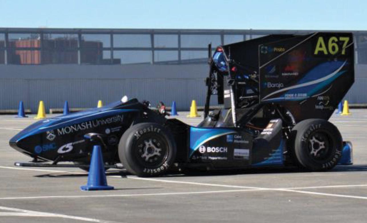
Monash Motorsport is a student run Formula Student team from Monash University. The autonomous vehicle, M19-D, [Fig.1] retrofits a suite of autonomous systems onto the team’s 2017 first-generation driven electric vehicle to produce a driverless race car. The autonomous pipeline is achieved by integration of software and hardware, as seen in [Fig. 2].
This pipeline is tailored to meet the needs of dynamic events in competition. These events include Acceleration, Skidpad, Autocross and Trackdrive. Autocross is a single lap of an unknown track. This is the most demanding event on the pipeline due to the real-time discovery of the track whilst planning the path and controlling motion. It is also as demanding on the computing as it is the software. Trackdrive is ten laps of the known Autocross track. Skidpad is a figure eight track driving two laps in the right-hand loop followed by two laps in the left-hand loop. Acceleration involves accelerating in a straight line before coming to a controlled stop.
Monash Motorsport uses Robot Operating System (ROS) [1] as the main framework for developing software packages operating within a Linux Operating System. Sections within the software structure include Perception, State Estimation, Path Planning and Motion Control. Perception takes data inputs from the Baraja Spectrum-Scan™ LiDAR [2] and the stereoscopic cameras to determine
Abstract
This paper explores the software and hardware architecture developed for an autonomous race car namely the Monash Motorsport autonomous race car. This report will cover the structure and flow of information throughout the autonomous systems pipeline by examining the series of packages that provide solutions to essential robotics problems. These include perception, localisation, mapping, motion planning and control. The system was developed for robustness and reliability, especially within an unknown track, whilst also trying to maximise speed. The MMS hardware systems used for integrating software and actuation are also explored, as well as safety critical systems, and the sensor suite used as perception inputs.
KEYWORDS: Autonomous; Software pipeline; Autonomous integration; Autonomous Vehicles the locations, size, and - where possiblecolours of cones on the track. Simultaneous Localisation and Mapping (SLAM) is used to create a map of the racetrack while also estimating, in real-time, where the car is within that track as accurately as possible. Path Planning takes in cone locations from SLAM, and outputs reference points along the path to Motion Control. Path Planning allows for the reliable traversal of an unknown track. It also provides the optimal path to take for the quickest lap times following complete mapping of the track. The role of Motion Control is to compute acceleration and steering requests to follow the trajectory generated by Path Planning in real-time within the presence of noise, disturbances, and other uncertainties.

The role of Actuation in the pipeline is to provide an interface between the software domain of the pipeline with the physical hardware involved in controlling the car. Importantly, actuation transforms the Motion Control requests into low level controls for steering, acceleration and braking as well as facilitating safety systems.
The specific function of each subsection will be explored in more detail in Section 4, 5, 6, 7 and 8.
2. Hardware and Computing
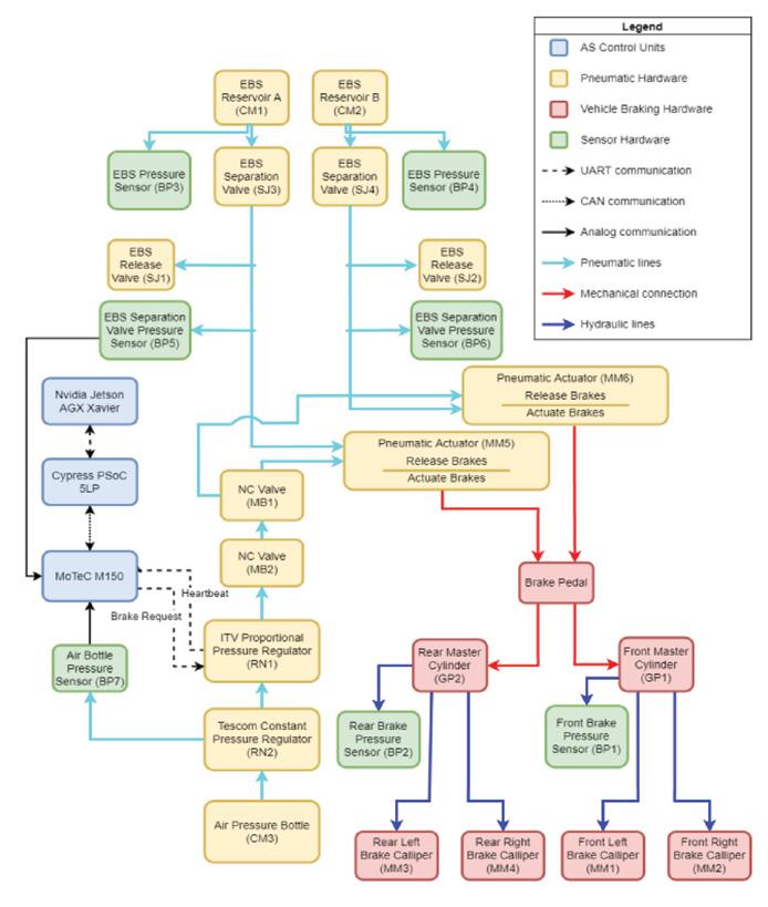
Monash Motorsport’s Autonomous Pipeline relies on multiple hardware components to enable effective computation, integration with the existing vehicle’s platform, and actuation, detailed in [Fig. 3]. The main components of the pipeline comprise of a NVIDIA Jetson AGX Xavier, a Programmable System on a Chip (PSoC), a Remote Emergency System (RES), pneumatic braking and safety systems, a steering servo motor and the autonomous racecar itself.

An important consideration with the autonomous hardware is integration with software in the Autonomous Pipeline, as well as the low (LV) and high voltage (HV) systems on the racecar. The Computing section achieves this through electrical wiring looms and a custom state machine implementation on the PSoC. Computing is responsible for providing the other sections of the pipeline with sufficient processing power to function. It must be robust and as wellpackaged as possible to reduce the impact on the performance M19-D as a racecar. Key hardware components are detailed in the following sections.
2.1 Hardware
2.1.1.
The central piece of hardware for the Autonomous Pipeline is in no doubt the computer. It facilitates the execution of all the high-level software for the Autonomous Pipeline. This is the handling and processing of data from sensors, computation of the autonomous algorithms, and outputting of signals to other systems in the car. In 2019, the processing units consisted of a NVIDIA TX2 and an Intel i7 8700. The TX2 with 6.2 CUDA Architecture had a reasonably powerful GPU while consuming very low power (15 Watts), however had a very poor CPU performance. The i7, mounted on a Mini-ITX motherboard with 8GB RAM, had significantly better CPU performance, acting as the main processing unit of the autonomous system. Having two separate processing units on a racecar which is both mobile and batterypowered, has obvious disadvantages in terms of mass and power consumption. Due to this, a new computer was sought after to suit the computing requirements of the Autonomous Pipeline better.
Now, both TX2 and i7 have been replaced with the NVIDIA Jetson AGX Xavier [3] (referred to as Xavier), a unified-memory low-power (30 Watt) computer. It is ten times more powerful than the TX2 with 32GB shared between the GPU and CPU, two ‘Deep Learning Accelerators’, and 8 Core ARM CPU. It can handle and facilitate the processing of data from sensors, computation of the autonomous algorithms. Its features allow for object detection on LiDAR 3D point clouds, as well as various optimisations across the Autonomous Pipeline.
2.1.2.
Programmable System on a Chip
A Programmable System on a Chip 5LP [4] is a low-cost, and easily programmable microcontroller with many configurable digital and analogue peripherals used to bridge the vehicle’s Electrical Control Unit and Xavier. Low level software allows for the management of digital inputs and outputs for various signals. It is mounted to a custom designed Statemachine Support Circuitry PCB, which processes the electrical input and output signals between the PSoC and ensures signals are at required voltages for various devices and signals. In addition, the Statemachine Support PCB mounts the ICs and relays needed for communications and for enabling power to autonomous vehicle actuation components such as the steering motor, pressure regulator, and solenoids.
2.1.3. Electrical Control Unit
M19-D is equipped with a MoTeC M150 Electrical Control Unit (ECU) [5] as a pre existing component on the 2017 electric car. The ECU sends relevant requests to various electrical systems on the car based on inputs from the PSoC. It sends signals to the inverter - as well as requests to the braking system and the steering motor.
2.1.4. Remote Emergency System
The Remote Emergency System (RES) is critical to autonomous safety as it allows for an emergency stop request to be made from a distance. It consists of a radio transmitter and receiver. It also is used to communicate with the car to begin autonomous driving. The RES used is specified by competition rules and is a Gross-Funk GF2000i-codec/T53R98 combination [7].
2.1.5. Hardware Packaging
All the required components for the autonomous system are packaged in an aluminium box, to ensure protection from the environment, typically referred to as the computing box. Located on the middle right of the vehicle, as shown in Fig. 4, the box is easily accessible and close to the vehicle’s centre of gravity. The interior of the box contains a number of vertical shelves of aluminium plates, on which the computing units are mounted, allowing for serviceability.
2.3 Electrical Loom
A custom electrical wiring loom provides power to and communication between all computing units and actuation hardware on the car. Hence it is essential that the electrical loom is robust and easily serviceable. Utilising the vehicle’s Low Voltage (LV) battery as the power source, 22-18 AWG wires are used to provide sufficient electrical power, current and signals into the computing box through a Deutsch AutoSport and Souriau UTO industrial connector, for high density grouping and isolating the box from the rest of the car’s loom. The loom itself is custom made by the team, in order to tailor to particular connections and achieve ideal wire lengths. The main connectors used in the computing box are Deutsch DTM connectors as well Molex Micro-Fit 3.0 for PCB mounts.
2.4 Communications
Communications from the PSoC and Xavier are executed through UART while the ECU and PSoC are connected over a CAN bus. Kinematic requests from the Xavier are relayed to the MoTec M150 unit through the PSoC. Conversely, sensor readings from the MoTec M150 such as rack travel, wheel speeds, IMU, and ASB, are inputs provided to the PSoC and the Xavier.
The computing box also contains an 8 port switch and router which allows the LiDAR sensor and GPS to communicate to the Xavier over ethernet, and provides live telemetry.
2.5 Safety Systems
There are additional safety measures to be followed for an autonomous racecar in Formula Student. Safety Critical Signal (SCS) measures and Emergency Braking System (See section 8.2) are some of the additional systems that are accounted for in Computing through both hardware and software. SCS are all electrical and autonomous related signals that influence the vehicle. They are continuously monitored by the ECU and Statemachine for signal failure (e.g., open circuit, short circuit, data corruption, loss and delay of messages) and in the case that a failure occurs, brings the vehicle to a safe state.

The shut-down circuit (SDC) is a serial electrical circuit connected to several safety monitoring devices that enables the vehicle’s high voltage system if all the safety requirements are passed. The EBS interlock is also part of the SDC, which opens the SDC if the autonomous pipeline fails and immediately activates the EBS. The interlock functions as hardware logic and requires the RES to be turned on, as well as the computing processes and SCS monitoring to be in a satisfied state, for it to close the SDC.
3. Software Stack
Monash Motorsport’s Autonomous Pipeline includes a suite of software packages in which sensor data is handled and processed, and autonomous algorithms and safety systems are run.
The software which uses ROS, such as Perception, SLAM, Path Planning and Motion Control, is run on the Xavier using the Ubuntu 18.04 LTS distribution of Linux [6], and primarily built on the ROS software framework. Most real time autonomous software is written in C++ due to its native support by ROS and low computation times. PSOC code is written in C, Python is used for post testing analysis tools and simulation, and MoTeC’s own C-like programming language is used for the ECU [8]. To enable fast development and deployment of the autonomous systems, a custom simulation environment has been created. This is particularly beneficial for testing new developments and changes prior to on-track testing.
Monash Motorsport uses Continuous Integration and Continuous Development (CI/CD) practices, and version control [9] to support efficient and high-quality development and deployment of software across the Autonomous Pipeline. Continuous Integration is implemented in Jenkins and runs simulations of every change submitted in a pull request, using the custom simulation environment and suites of unit tests, minimising software errors before on-track use.
Data is collected from both simulated and ontrack testing in the form of ROS bags, which contain information from software as well as sensors on the car, for each test run. This data can then be analysed, and data from sensors such as the LiDAR point cloud can be used as inputs in simulation, to test software changes on real-world data.
4. Perception
4.1 Baraja Spectrum-Scan™ LiDAR
A Baraja Spectrum-Scan™ LiDAR supplied by the Australian deep technology company Baraja Pty Ltd, is used to provide a highresolution point cloud of the environment in front of the car. Baraja’s LiDAR solution outputs a dense point cloud spectrum with a range of 240m and a horizontal FOV of 120°. This allows the MMS autonomous pipeline to see further and allows greater speed of the vehicle due to the larger range and certainty of landmark positions compared to results obtained from alternative LiDAR solutions used by the team previously.

4.1.1. Cone Clustering Algorithm

The point cloud spectral information preprocessing phase removes unnecessary spectral information. Post processing involves a Euclidean Clustering algorithm along with implementation of a K-D tree data structure for efficient identification of neighbour associations. The Point Cloud Library (PCL) [10] implementation was utilised with CUDA GPU to free CPU usage and employ multithreaded processing to compute the point cloud data. Previous iterations of clustering utilised single-threaded CPU to cluster cones and was at times taking longer than 1 second to compute the dense point clouds, affecting the car’s performance. The CUDA GPU implementation demonstrated a significant performance improvement via a reduction of latency of dense point cloud computations (<10ms) overusing the CPU.
4.1.2. LiDAR Neural Network

The PointPillars neural network [11] is used to detect cones in three-dimensional space. It has a low latency in contrast to other point cloud detection networks due to its lack of 3D convolutions. It is actively trained on data collected by Monash Motorsport on a Baraja Spectrum-Scan™ LiDAR. The PointPillars neural network also displays a higher mean Average Precision over pure clustering algorithms, which permits more accurate cone detections with fewer false cones due to other objects in the environment [11].
4.2. Stereoscopic Cameras
A pair of Basler ace acA2440-75um mono cameras are used to enable visible light imaging and depth perception. This in turn allows the identification of cone colours, which assists Path Planning in determining the left and right side of the track as well as the starting orange cones. Additionally, cameras also enable the detection of cone location, complementing the location of cones inferred from LiDAR data.
4.2.1. YOLOV3
The You Only Look Once version-3 (YOLOV3)
[12] architecture is an object-detection neural network working with visible light images to detect specified landmarks with the Stereoscopic cameras. In the case of Monash Motorsport, YOLOV3 is used alongside peleenet [13] which is used as the backbone of the network due to its speed and functionality to detect cones on track.
5. Simultaneous Localization and Mapping
5.1 Sensors
A combination of state sensors (Inertial Measurement Unit (IMU), GPS, and Magnetometer) and observation sensors (Baraja Spectrum-Scan™ LiDAR and cameras) are utilised. The state sensors provide information about the vehicle state while the observation sensors provide information about surroundings and also the vehicle’s state, relative to its surrounding environment. The vehicle hosts a Swift Piksi Multi GNSS module [14] which has an integrated IMU and Magnetometer that is connected to the TW3870 Dual Band GNSS Antenna and Xavier computing unit via a switch. This unit was chosen for its fast fix time (< 60s) and refresh rate (10Hz), robust positional data (0.75m horizontal accuracy with standalone GPS or 0.001m with dual GPS Real Time Kinematic setup) and ease of integration due to a prototyping friendly PCB and pre-existing support with ROS drivers.
5.2 Sensor Calibration
To ensure robust measurements, calibration of the sensors is required. The state sensors are all calibrated live during each race on the car to ensure that their measurements are reliable. A buffer of GPS, magnetometer and IMU measurements are stored at the starting line while the vehicle is stationary and used to find the average initial measurements on vehicle start. This is done to find the GPS position to be used as the origin, and orientations of the IMU and magnetometer. The GPS frame is then rotated onto the car’s frame by calculating the difference in angle between the two. To ensure minimal error during live calibration, an arc-length comparison algorithm, that compares the GPS’s changing position and the SLAM algorithm’s estimate of the changing position, is used to spot noisy GPS measurements. The IMU and magnetometer are on the same PCB and are not perfectly aligned with the centre of gravity of the vehicle, and so must be calibrated. This is done under the assumption that the vehicle is stationary and only subjected to downwards acceleration due to gravity. The IMU and magnetometer measurements are then rotated with a calculated quaternion to align the axis of the board to be coincident with the axis of the car’s frame.
Prior to using the readings from the magnetometer, hard and soft iron magnetic field interference [15] must first be removed from measurements. This is done by storing live measurements from the magnetometer. The resulting measurements trace out an ellipse; calculating the transformations that turn this ellipse back into a circle and applying this to subsequent live readings removes this interference, resulting in a reliable heading.
5.3 Extended Kalman Filter
There is extensive research and varying approaches to the SLAM problem such as the Kalman Filter, GraphSLAM [16] and FastSLAM [17]. For the purpose of the Monash Motorsport pipeline, the Extended Kalman Filter (EKF) variant was selected due to its relatively simple implementation, solves the non-linear estimation problem and suitable to the low landmark environment of Formula student competition.
The notable disadvantages of the EKF algorithm is that it linearises the vehicle and observation model which introduces approximation error. The computational complexity is O(n2) in the update-step [18] where n is the number of landmarks. These disadvantages are somewhat mitigated due to the low number of landmarks of approximately 200-300 for larger tracks. The approximation error is reduced with fast periodic prediction and correction steps (50Hz).
The EKF algorithm can be considered as a decision-level sensor fusion algorithm, as each sensor is able to provide corrections via observation of the vehicle state. This allows for sensors to be turned on and off and adjusted individually without affecting the EKF implementation.
The cone detections from Perception are treated as the landmarks that are continually added to the map in positions relative to the vehicle’s position estimate. Data association occurs between cones that are within either the Euclidean or Mahalanobis distance of each other. These two cones are assumed to be the same, and are combined with their position adjusted. Over the course of a lap, there is an error associated with the landmark and vehicle state which will propagate map errors to later landmark additions. Loop closure is performed to reconcile the two differing estimates of the same landmark. The Autocross and Trackdrive tracks are closed loops where the car will return to the same initial location at the end of each lap and observe the starting cones. A loop closure algorithm matches these known unique cones observed at the start and end of a lap. The track is shifted to connect the end of the track to the start due to the greater confidence in the position of the cones observed at the beginning of the race. As the vehicle is operating in a static environment, the map is no longer altered after loop closure which reduces the computational load required for later laps.
While EKF provides a suitable solution to the SLAM problem, other algorithms are being investigated for future development, including the Sparse Extended Information Filter [21], Unscented Kalman Filter [22], GraphSLAM [16] and FastSLAM [17].

6. Path Planning
6.1 Track Discovery
In Autocross, Skidpad and Acceleration events, there is no prior knowledge of the track. As such, Path Planning must construct a track to navigate through based on SLAM’s landmark map, which is continuously updated as the car moves.
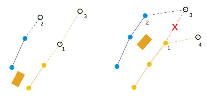
The algorithm used to construct the track is Delaunay triangulation. Delaunay triangulation forms triangles from points in a given space so that no point lies within the circumcircle of any triangle, helping produce geometrically balanced triangles [21]. Cost functions are used to choose triangles to fit a Bezier-Spline [22] through the midpoint of triangle vertices, representing cone pairs on either side of the track, see Figure 7. Cost functions include the distance between consecutive cones on one side of the track, the smoothness of the sides and centerline of the track, the circumradius, and cone colours if available. The track selection is robust even without use of cone colours. As seen in Figure 8, new triangles and the spline path are continuously updated as more information is provided from SLAM.
6.2 Optimal Racing Line
Following the completion of the first lap of track drive, the trackmap is saved as a series of transverse lines drawn between the two sides of the track. From this, the Optimal Racing Line (ORL) is calculated by using a custom trajectory optimisation algorithm which aims to minimise lap time within the restraints of vehicle dynamics, such as longitudinal and latitudinal jerk of the vehicle, vehicle speed and the width of the track. This is achieved using the Levenberg-Marquardt Algorithm, coupled with leapfrog integration [23]. From this ORL, a velocity profile can be generated and maximum accelerations of the vehicle can be fitted [24] [25].
7.
7.1
Pure Pursuit
Pure Pursuit is a basic Motion Control algorithm. It relies on the kinematic bicycle model to determine the required steering angle to reach a lookahead point on the given path. The pipeline uses a variant of Pure Pursuit that varies the lookahead point based on the curvature of the track. On straights, the lookahead point will be further away and the steering will be more stable, whereas for corners it will be closer and the steering more responsive. As a result, with a larger lookahead point, the steering is damped. This makes Pure Pursuit a strong solution for the straight line Acceleration event. However, in events that require more cornering, such as Autocross and Trackdrive, the lookahead distance needs to be smaller. The main downside of this algorithm is the instability as Pure Pursuit can overcorrect in steering to the next lookahead point. Generally, the controller undershoots on corners, overshoots on straights and steers too much. The shortcomings with steering are a bigger problem in formula student events given the challenging track characteristics, such as the narrow track (3m width), hairpins and slaloms. Hence development of a more sophisticated controller for the Autocross and Trackdrive events was required to overcome this problem.

7.2 Model Predictive Control
Model Predictive Control (MPC) is a form of optimal control that uses a receding prediction horizon to compute the current optimal controls for a given objective function. Specifically, a linear time varying MPC is used for the pipeline. The prediction is updated every time step and the vehicle only utilises the prediction for the current time period. This means that the present controls are optimised while considering the effects that these controls have on the future. The MPC optimises the car’s steering, throttle and braking requests to execute the trajectory given by Path Planning. The benefit of MPC is that it implicitly incorporates state and control constraints into the optimisation problem. Important constraints for this racecar application are maximum velocity, lateral deviation from the track centreline, and tyre stiffness. The constraints aim to keep the car on track and prevent instabilities such as oversteer. These constraints, in addition to the future control parameters, when calculating current controls are the reasons MPC is useful in the formula student application. One limitation of the current implementation of the MPC is the use of a kinematic bicycle model as the plant model which makes assumptions such as linear tyre models. However, for higher speeds these assumptions become inaccurate, and a dynamic bicycle model may become more suitable. The kinematic model was previously preferred due to better accuracy at lower speeds and lower computation time. Figure 10 demonstrates the increased performance of the linear time varying MPC compared to pure pursuit, as it pushes the car to its traction boundaries more. One drawback of MPC is the large computation time due to the optimisation processes [25], which may lead to instability. Hence MPC is not used in events with noncomplex tracks, such as the Acceleration event, where the MPC optimisations are not required.
8. Actuation
8.1 Low-level Control
As the section of the autonomous pipeline succeeding Motion Control, Actuation receives steering angle requests and velocity requests which are admitted to the MoTeC M150 ECU via the state-machine implementation on the Cypress PSoC 5LP. From a holistic view, the Actuation’s role is to provide an abstraction of the actuation hardware to the high-level software in the upper layers of the Autonomous pipeline. Functionally, actuation takes the requests from Motion Control and performs the processing and control required to realise these requests on the vehicle. The role of the MoTeC M150 ECU in the actuation context is thus to facilitate this functional role. Received steering angle requests are compared to the current steering angle as measured by a steering rack sensor. The difference in angle is then taken and converted into servo motor increments from the current position. This is then encoded and sent via CANOpen to the Moog SmartMotor.

Velocity actuation is facilitated by a cascade controller. Received velocity requests are first passed to a proportional controller implementation on the ECU. This velocity request is compared to the current speed of the car (the response) as measured by wheel speed sensors for the front, undriven wheels of the vehicle to produce an error value for the velocity. This velocity is then scaled with the proportional coefficient to produce a target acceleration. The value of the target acceleration then determines whether the car is to coast, accelerate or brake. If the target acceleration is high enough, it is passed to the acceleration PI controller which then produces a request that is sent to the vehicle’s inverter. Conversely, the target acceleration is sent to the braking PI controller which then produces a pressure request that is sent to the service brake pressure regulator.
8.2 Braking and Safety
The braking system is the most critical safetyrelated component on the driverless vehicle. The vehicle must be able to safely stop itself at any time regardless of the state of the carpowered or otherwise.
This function is facilitated by the Remote Emergency System (RES) in tandem with the EBS. The MMS EBS implementation is a pneumatic actuation system that is retrofitted onto the pre-existing braking line. It consists of two air reservoirs for redundancy, should one of the reservoirs fail to actuate when required. When the reservoirs are pressurised, they provide a constant force on the brake pedal that keeps the brake pedal fully engaged in the absence of an opposing force against the EBS. The design of this was intentional as to keep the brakes fully engaged by default. When the vehicle is required to accelerate, the acceleration PI controller sends a nonzero encoded pressure request to a pressure regulator connected to the service brake side of the EBS actuator. The force from the pressure on the service brake side then opposes the constant force provided by the filled EBS reservoirs. This effectively releases the brakes on the vehicle and allows it to accelerate or perform intermediate braking. The EBS is constantly connected to the RES, which upon activation causes the car to lose all power and causes the pressure regulator connected to the service brake side of the EBS actuator to release all pressure. This in turn allows the force from the pressure on the EBS side of the actuator to fully engage the brakes and bring the car to a safe stop.
8.3
Steering
Steering requests on the Autonomous vehicle are ultimately serviced by a Moog SmartMotor servo which is mated to a reduction gearbox and manipulates the steering column via a belt.
The servo motor takes in requests for relative movement in the form of signed motor increments from its current position. These requests are made via the CANOpen application layer protocol and transportation of these messages is done via the CAN data link layer protocol. Upon successful reception of these requests, the servo motor utilises an internal PID controller alongside set acceleration and velocity targets to realise the requests on the steering column.
9.
Conclusion
An overview of an autonomous pipeline has been illustrated through examining both the software and hardware involved in the system and their respective functions. The software packages have been developed for our Formula Student Driverless application and the hardware has been specifically chosen for reliability and performance.
Future developments include a focus on lower latency landmark association and mapping given the increased range of the Baraja Spectrum-Scan™ LiDAR. This should allow us to discover new tracks faster leading to more stability in Path Planning and Motion Control. This increased range means that we can push the car harder when discovering to minimise lap time. This is important because of the limited computational resources given the capabilities of the Xavier. The team is always looking to increase the efficiency and latency of algorithms so that the autonomous vehicle problem can be solved faster. Future developments for motion planning include better control of the vehicle so that calculation of the optimal racing line is achievable with reliability. Furthermore, better control of the vehicle means the car’s speed can be maximised without sacrificing reliability. This can be achieved by a more accurate plant model for the MPC. Also, reducing the delay in the pipeline will lead to better MPC performance. Formula Student Driverless is a constantly evolving competition which requires continuous effort to improve current driverless systems.
Acknowledgement
We would like to thank all present and past members of Monash Motorsport, especially our former and founding members of the Autonomous Department for laying the foundations on which we build upon today. We have been truly lucky enough to stand on the shoulders of giants. Equally, thank you to Monash University, and our sponsors, particularly Baraja, SMC, Xenon, and Adept Turnkey, for providing us with the trust and support that allows us to reach our potential.


