23 minute read
Helicopter Landing Areas Physical Characteristics


3
Advertisement
3.1 General
This section provides information on physical requirements for the characteristics of helicopter landing areas on a yacht within the scope of the Code.
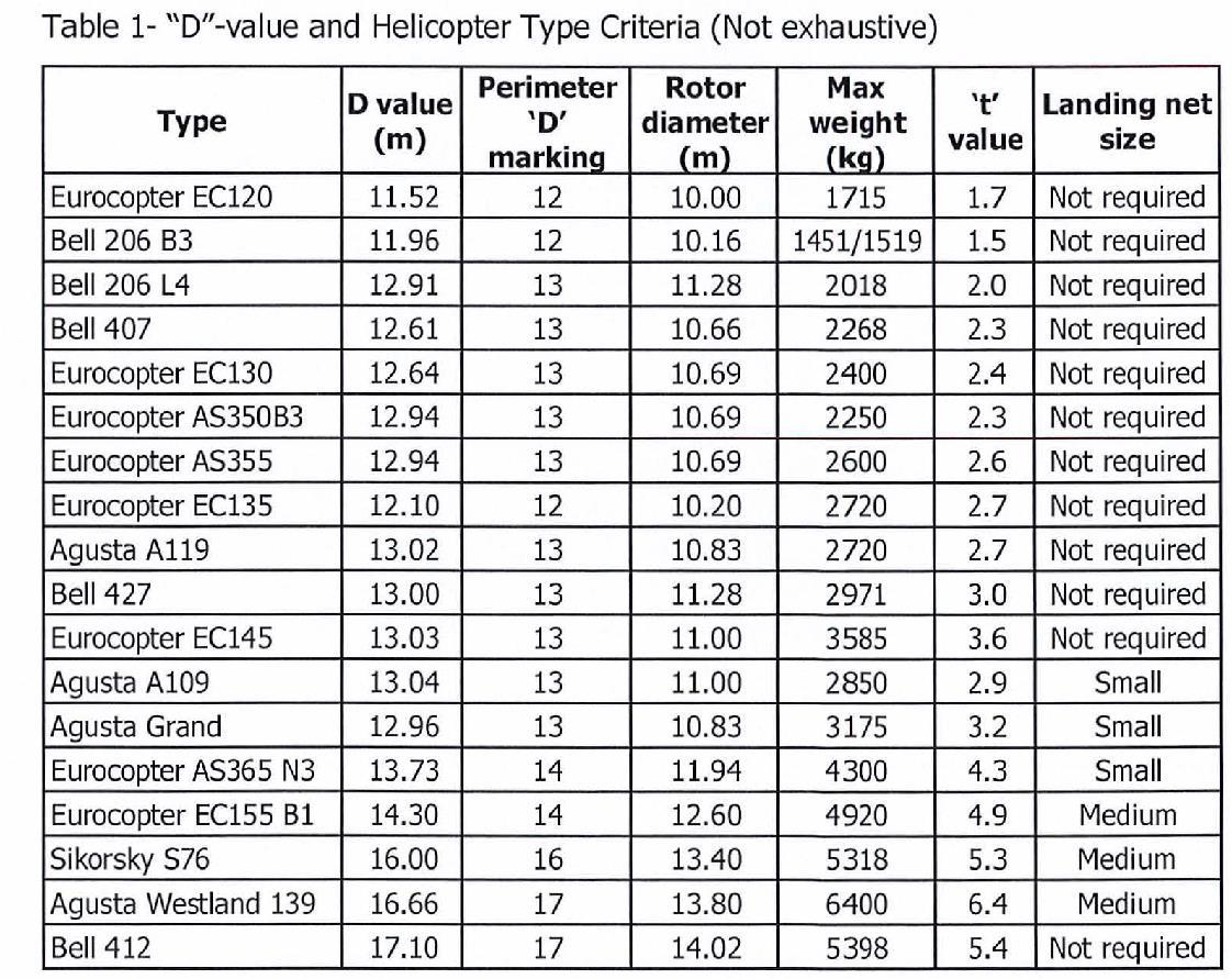
3.1.1 The risk assessment carried out as above in order to establish the adequacy of the landing area should include, for each helicopter landing area, the proposed maximum size of helicopter in terms of "D"-value and the proposed maximum takeoff weight of the heaviest helicopter in terms of "t" value for which it is proposed each landing area is certificated with regard to size and strength. In addition to the risk assessment, the following plans and particulars should be submitted to the Aviation Inspection Body, Certifying Authority and Administration (as appropriate) for approval:
.1
.2 .3 .4 Hangar general arrangement (showing dimensions and structural considerations ) . Helicopter lift and movement arrangements (if appropriate) . Structural fire protection . Fire detection and extinguishing arrangements
3.1.2 The criteria which follow are based on helicopter size and weight and are for guidance only.
3.1.3 Where skid fitted helicopters are used routinely, landing nets are not recommended.
3.2 Helicopter Landing Area Design Considerations - Environmental Effects
3.2.1 Introduction
The safety of helicopter flight operations can be seriously degraded by environmental effects that may be present around vessels. The term "environmental effects" describes the effects of the vessel, its systems, and forces in the surrounding environment, which result in a degraded local environment in which the helicopter is expected to operate. These environmental effects are typified by structure-induced turbulence, and turbulence/thermal effects caused by exhaust emissions. Controls in the form of landing area availability restrictions may be necessary and should be imposed via the Aviation Inspection Body. Such
restrictions can be minimized by careful attention to the design and layout of the vessel topsides and, in particular, the location of the helicopter landing area.
3.2.2 GUIDANCE FOR LANDING AREA DESIGN CONSIDERATIONS
3.2.2.1 Guidance for landing area design considerations are given in UK Civil Aviation Authority Paper 2004/02 which should be consulted by designers of helicopter landing areas at the earliest possible stage of the design process and is available through the CM website (www.caa.co.uk).
3.2.2.2 All new helicopter landing areas, or modifications to existing topside arrangements which could potentially have an effect on the environmental conditions due to turbulence around an existing helicopter landing area, or helicopter landing areas where operational experience has highlighted potential airflow problems should be subject to appropriate wind tunnel testing or CFD studies to establish the wind environment in which helicopters will be expected to operate. As a general rule the standard deviation of the vertical airflow velocity should be limited to 1.75m/s. The helicopter pilot/operator and Aviation Inspection Body should be informed at the earliest opportunity of any wind conditions for which this criterion is not met in order to allow the appropriate platform availability restrictions/limitations to be defined if necessary.
3.2.2.3 Designers of helicopter landing areas should commission a survey of ambient temperature rise based on a Gaussian dispersion model and supported by wind tunnel tests or CFD studies for new build helicopter landing areas, modifications to existing topside arrangements, or for helicopter landing areas where operational experience has highlighted potential thermal problems. When the results of such modelling and/or testing indicate that there may be a rise of air temperature of more than 2°C (averaged over a 3 second time interval), the helicopter pilot/operator and Aviation Inspection Body should be consulted at the earliest opportunity so that appropriate platform availability restrictions/limitations may be applied if necessary.
3.2.3
SIZE OF LANDING AREA AND OBSTACLE PROTECTED SURFACES For any particular type of single main rotor helicopter, the helicopter landing area should, wherever possible, be sufficiently large to contain a circle of diameter D equal to the largest dimension of the helicopter when the rotors are turning. This "D" circle should be totally unobstructed (see Table 1 for "D"-values). Due to the actual shape of most helicopter landing areas the "D" circle will be
'imaginary' but the helicopter landing area shape should be capable of accommodating such a circle within its physical boundaries. It is possible to reduce the width to a value equivalent of 0.83D but the longitudinal length must be at least equivalent to 1.0D.
3.2.3.1 For operations with limited touchdown directions, contain an area within which can be accommodated two opposing arcs of a circle with a diameter of not less than 1D in the helicopter's longitudinal direction. The minimum width of the landing area shall be not less than O.83D. In such arrangements of landing areas, the yacht will need to be maneuvered to ensure that the relative wind is appropriate to the direction of the helicopter touchdown heading. The touchdown heading of the helicopter is limited to the angular distance subtended by the 1D arcs headings, minus 15 degrees at each end of the arc. See diagram below.
3.2.3.2 From any point on the periphery of the above mentioned "D" circle an obstaclefree approach and take-off sector should be provided which totally encompasses the safe landing area (and "0" circle) and which extends over a sector of at least 210°. Within this sector, from the periphery of the landing area and out to a distance that will allow for an unobstructed departure path appropriate to the helicopter that the landing area is intended to serve, only the following items may exceed the height of the landing area, but should not do so by more than 250 millimeters (no infringements within the "0" circle): • The guttering (associated with the requirements in paragraph 3.2.4.2);

• The lighting required by paragraph 3.7; • The foam monitors; • Those handrails and other items associated with the landing area which are incapable of complete retraction or lowering for helicopter operations.
3.2.3.3 The bisector of the 210° obstacle free sector (OFS) should normally pass through the center of the "0" circle. The sector may be 'swung' by up to 15° as shown in Figure 1 below. Acceptance of the 'swung' criteria will normally only be applicable to existing vessels.
3.2.3.4 The diagram at Figure 1 shows the extent of the two segments of the 150° Limited Obstacle Sector (LOS) and how these are measured from the center of the (imaginary) '0' circle and from the perimeter of the safe landing area (SLA). This diagram assumes, since helicopter landing areas are designed to the minimum requirement of accommodating a 1 '0' Circle, that the 'D' circle perimeter and SLA perimeter are coincidental. No objects above 0.050 are permitted in the first (hatched area in Figure 1) segment of the LOS. The first segment extends out to 0.62D from the center of the '0' Circle, or 0.120 from the SLA perimeter marking. The second segment of the LOS, in which no obstacles are permitted within a rising 1:2 slope from the upper surface of the first segment, extends out to 0.830 from the center of the '0' Circle, or a further 0.210 from the edge of the first segment of the LOS. The exact point of origin of the LOS is assumed to be at the periphery of the '0' Circle.
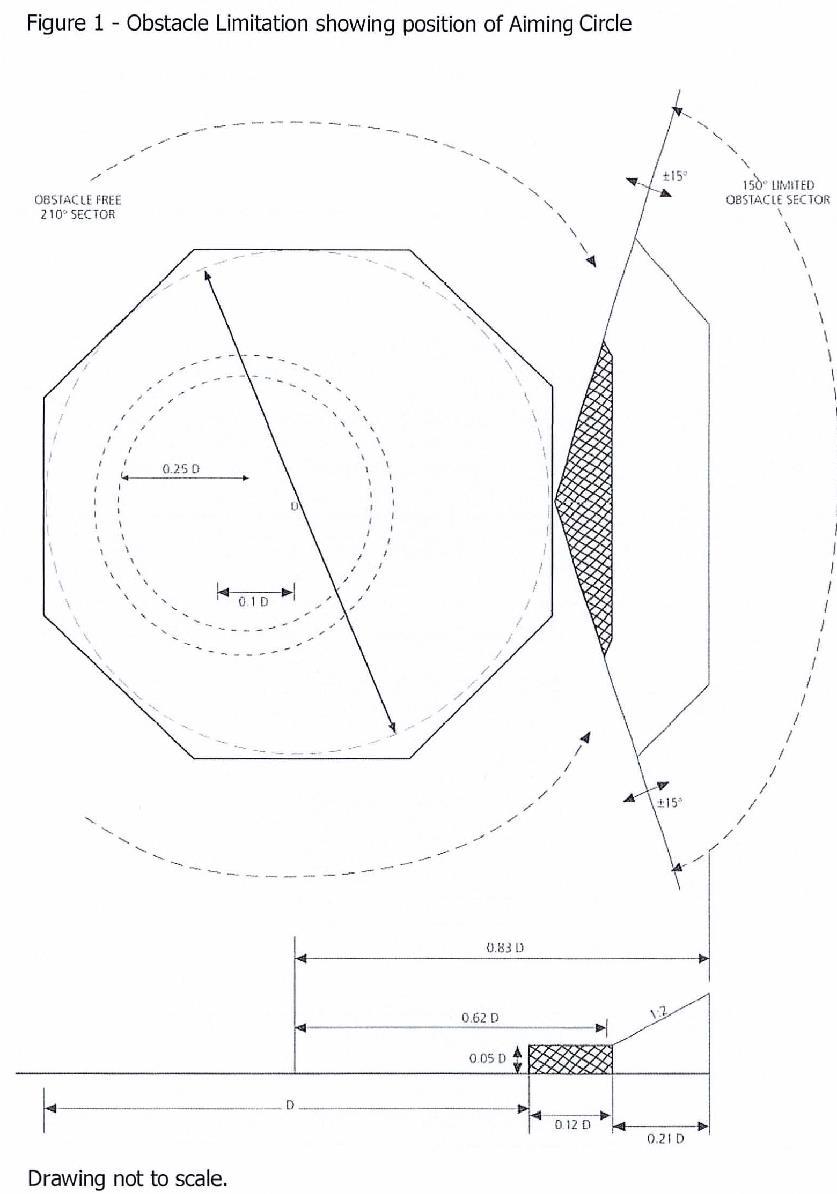
3.2.3.5 Some helicopter landing areas are able to accommodate a SLA which covers a larger area than the declared 'Of-value; a simple example being a rectangular deck with the minor dimension able to contain the 'Of circle. In such cases it is important to ensure that the origin of the LOS (and OFS) is at the SLA perimeter as marked by the perimeter line. Any SLA perimeter should guarantee the obstacle protection afforded by both segments of the LOS. The respective measurements of 0.120 from the SLA perimeter line, plus a further 0.210 are to be applied. On these larger decks there is thus some flexibility in deciding the position of the perimeter line and SLA in order to meet the LOS requirements and when considering the position and height of fixed obstacles. Separating the origin of the LOS from the perimeter of the 'D' circle in Figure 1 and moving it to the right of the page will demonstrate how this might apply on a rectangular SLA.
3.2.3.6 The extent of the LOS segments will, in all cases, be lines parallel to the SLA perimeter line and follow the boundaries of the SLA perimeter (see Figure 1 above). Only in cases where the SLA perimeter is circular will the extent be in the form of arcs to the 'D' circle. However, taking the example of an octagonal SLA as drawn at Figure 1, it would be possible to replace the angled corners of the two LOS segments with arcs of 0.12D and 0.33D centered on the two adjacent corners of the SLA; thus cutting off the angled corners of the LOS segments. If these arcs are applied they should not extend beyond the two corners of each LOS segment so that minimum clearances of 0.12D and 0.33D from the corners of the SLA are maintained. Similar geometric construction may be made to a square or rectangular SLA but care should be taken to ensure that the LOS protected surfaces minima can be satisfied from all points on the SLA perimeter.
3.2.4 LANDING AREA SURFACE
3.2.4.1 The landing area should have an overall coating of non-slip material and all markings on the surface of the landing area should be made with the same nonslip materials. Whilst extruded section or grid construction aluminum (or other) decks may incorporate adequate non-slip profiles in their design, it is preferable that they are also coated with a non-slip material unless adequate friction properties have been designed into the construction. It is important that the friction properties exist in all directions. Over-painting friction surfaces on such designs may compromise the friction properties. Recognized surface friction material is available
commercially.
3.2.4.2 Helicopter landing areas should be cambered to a maximum gradient of 1:100. Any distortion of the helicopter landing area surface due to, for example, loads from a helicopter at rest should not modify the landing area drainage system to the extent of allowing spilled fuel to remain on the deck. A system of guttering should be provided around the perimeter to prevent spilled fuel from falling on to other parts of the vessel and to conduct the spillage to an appropriate drainage system . The capacity of the drainage system should be sufficient to contain the maximum likely spillage of fuel on the deck. The calculation of the amount of spillage to be contained should be based on an analysis of helicopter type, fuel capacity, typical fuel loads and uplifts. The design of the drainage system should preclude blockage by debris. The helicopter landing area should be properly sealed so that spillage will only route into the drainage system.
3.2.4.3 For operations in adverse weather conditions a tautly-stretched rope netting should be provided to aid the landing of helicopters with wheeled undercarriages. The intersections should be knotted or otherwise secured to prevent distortion of the mesh. It is preferable that the rope be 20 mm diameter sisal, with a maximum mesh size of 200 mm. The rope should be secured every 1.5 meters round the landing area perimeter and tensioned to at least 2225 N. Netting made of material other than sisal may be considered but netting should not be constructed of polypropylene type material which is known to rapidly deteriorate and flake when exposed to weather. As a general rule, it should not be possible to raise any part of the net by more than approximately 250 mm above the helicopter landing area surface when applying a vigorous vertical pull by hand. The location of the net should ensure coverage of the area of the aiming circle but should not cover the helicopter landing area identification marking or 't' value markings. Some nets may require modification to outboard corners so as to keep the identification marking uncovered. In such circumstances the dimensions given in Table 2 below may be modified.
3.2.4.4 There are three sizes of netting as listed below in Table 2. The minimum size depends upon the type of helicopter for which the landing area is to be used as indicated in Table 1. Sizes are presented here for guidance only and nets of other sizes may be acceptable providing arrangements cover the whole of the aiming circle without obscuring the landing area identification markings.
Table 2 - Helicopter Deck Netting
Small Medium Large 9 meters by 9 meters 12 meters by 12 meters 15 meters by 15 meters
3.3 Helicopter Tie-Down Points
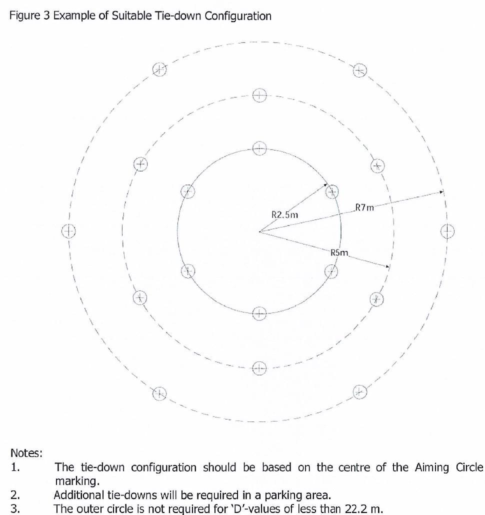
3.3.1 Sufficient flush-fitting (when not in use) or removable semi-recessed tie-down points should be provided for securing the maximum sized helicopter for which the helicopter landing area is designed. They should be so located and be of such strength and construction to secure the helicopter when subjected to expected weather conditions. They should also take into account the inertial forces resulting from the movement of the vessel.
3.3.2
Tie-down rings should be compatible with the dimensions of tie-down strop attachments. Tie-down rings and strops should be of such strength and construction so as to secure the helicopter when subjected to expected weather conditions. The maximum bar diameter of the tie-down ring should be compatible with the strop hook dimension of the tie down strops carried by the helicopter operator. An example of a suitable tie-down configuration is shown at Figure 3. The Aviation Inspection Body or helicopter operator will provide guidance on the configuration of the tie-down points for specific helicopter types.
3.4
Safety Net
3.4.1 Safety nets for personnel protection should be installed around the landing area where there is a danger of personnel falling overboard. This should be looked at on an individual basis and a suitable risk assessment conducted. Where adequate
structural protection against falls exists or adequate helideck procedures are in place with an appropriate risk assessment conducted and approved by the Administration, then safety nets may be omitted. If fitted, the netting used should be of a flexible nature, with the inboard edge fastened level, just below the edge of the helicopter landing area. The net itself should extend 1.5 meters in the horizontal plane and be arranged so that the outboard edge is not above the level of the landing area so that it has an upward and outward slope of at least 10°. It may be possible to incorporate dropped rails in place of a safety net but the dimensions and guidance above pertaining to safety net should be adhered to.
3.5 Access Points
3.5.1 Many helicopters have passenger access on one side only and helicopter landing orientation in relation to landing area access points becomes important because it is necessary to ensure that embarking and disembarking passengers are not required to pass around the helicopter tail rotor, or under the front of the main rotor of those helicopters with a low profile rotor, should a 'rotors-running turn-round' be conducted.
3.5.2 There should be a minimum of two access/egress routes to the helicopter landing area- these should be 1800 apart. The arrangements should be optimized to ensure that, in the event of an accident or incident on the helicopter landing area, personnel will be able to escape upwind of the landing area. Adequacy of the emergency escape arrangements from the helicopter landing area should be included in any evacuation, escape and rescue analysis for the vessel, and may require a third escape route to be provided.
3.5.3 Where foam monitors are co-located with access points, care should be taken to ensure that no monitor is so close to an access point as to cause injury to escaping personnel by operation of the monitor in an emergency situation.
3.5.4 Where handrails associated with landing area access/escape points exceed the height limitations given at paragraph 3.2.3.2 and 3.2.3.4 they should be retractable, collapsible or removable. When retracted, collapsed or removed the rails should not impede access/egress. Handrails which are retractable, collapsible and removable should be painted in a contrasting color scheme. Procedures should be in place to retract, collapse, or remove them prior to
helicopter arrival. Once the helicopter has landed, and the crew has indicated that passenger movement may commence, the handrails may be raised and locked in position. The handrails should be retracted, collapsed, or removed again prior to the helicopter taking-off. Where anti-collision lights are utilized, the helicopter crew will ensure they are switched off before the movement of passengers and/or freight takes place .
3.6 Visual Aids
3.6.1 The following sections outline the requirements for helicopter landing area markings which should be permanently painted on the deck. Plans of the marking arrangements including dimensions should be submitted to the Aviation Inspection Body for approval.
3.6.2 Helicopter landing area perimeter line marking and lighting serves to identify the limits of the Safe Landing Area (SLA) for day and night operations.
3.6.3 A wind direction indicator (windsock) should be provided during helicopter operations and located so as to indicate the clear area wind conditions at the vessel location. It is often inappropriate to locate the windsock as close to the helicopter landing area as possible where it may compromise obstacle protected surfaces, create its own dominant obstacle or be subjected to the effects of turbulence from structures resulting in an unclear wind indication. The windsock should be illuminated for night operations.
3.6.4
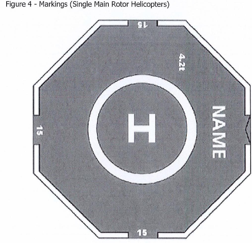
HELICOPTER LANDING AREA MARKINGS (SEE FIGURE 4 BELOW) For the smallest landing areas (typically < 16 m) it may be necessary to reduce the size of the helideck markings appropriately. In such circumstances, the Aviation Inspection Body should be consulted as soon as possible. The color of the helicopter landing area should where possible be a contrasting color to the rest of the vessel 's deck. The perimeter of the SLA should be clearly marked with a painted line 0.3 meters wide in a contrasting color to the helideck.
3.6.4.1 The light grey color of aluminum may be acceptable in specific helicopter landing area applications where these are agreed with the Aviation Inspection Body. This should be discussed in the early design phase. In such cases the conspicuity of the helicopter landing area markings may need to be enhanced by, for example, outlining the deck marking lines and characters with a thin black line. Alternatively, conspicuity may be enhanced by overlaying white markings on a painted black background.
3.6.4.2 A maximum allowable mass marking should be marked on the helicopter landing area in a position which is readable from the preferred final approach direction i.e. towards the obstacle-free sector origin. The marking should consist of a two or three digit number expressed to one decimal place rounded to the nearest 100 kg and followed by the letter 't' to indicate the allowable helicopter weight in tonnes (1000 kg). The height of the figures should be 0.9 meters with a line width of approximately 0.12 meters and be in a color which contrasts with the helicopter landing area surface (preferably white: avoid black or grey).
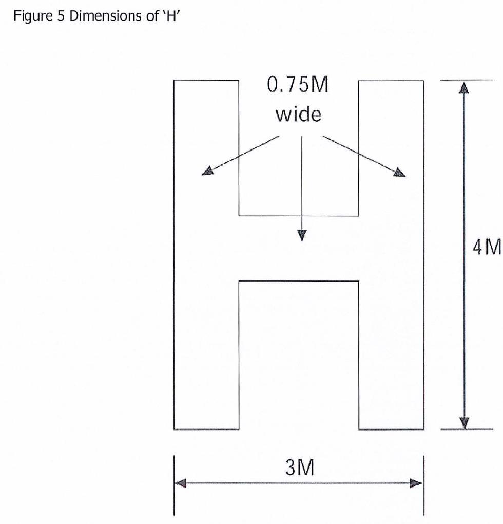
3.6.4.3 An aiming circle (touchdown/positioning marking) for each helicopter landing area should be provided as follows: (see Figures 4 and 5).
3.6.4.3.1 On smaller helicopter landing areas with a "O"-value up to and including 16.00 m and for bow-mounted helicopter landing areas the aiming circle should be concentric with the helicopter landing area center to ensure maximization of space all around for safe personnel movement and optimization of the visual cueing environment. On larger areas with a "O"-value greater than 16.00 m, the center of the aiming circle should be displaced 0.1 0 from the center of the "0" circle towards the outboard edge of the helicopter landing area along the bisector of the obstacle free sector in order to achieve an increased safety margin for tail rotor clearance. The marking should be a circle with an inner diameter of 0.5 times the certificated "O"-value of the helicopter landing area and a line width of not less than 0.5 m for landing areas with a "O"-value up to and including 16.00 m and not less than 1.0 m for landing areas with an "O"-value greater than 16.00 m. The circle should be in a contrasting color to the helideck.
3.6.4.3.2 On those decks where the aiming circle is concentric with the center of the 0 circle or SLA, the need for some mitigation against concerns over tail rotor clearances should be considered; either by achieving more obstacle clearance in the 1500 LOS or by adopting appropriate operational procedures (e.g. vessel to provide relative wind from beam or stern).
3.6.4.3.3 An "H" painted in a color contrasting with the deck (preferably white) should be co-located with the aiming circle with the cross bar of the "H" lying along the bisector of the obstacle-free sector. The minimum H dimensions are shown in
brackets for landing areas with a "O"-value up to and including 16.00 m, and without brackets for landing areas with a "O"-value greater than 16.00 m.
3.6.4.3.4 Where the obstacle-free sector has been swung in accordance with Section 3 paragraph 3.2.3.3 the positioning of the aiming circle and "H" should comply with the normal unswung criteria. The "H" should, however, be orientated so that the
bar is parallel to the bisector of the swung sector.
3.7 Lighting
3.7.1 The safe landing area (SLA) should be delineated by green perimeter lights visible omnidirectionally from on or above the landing area. These lights should be above the level of the deck but should not exceed the height limitations in paragraph 3.2.3.2. The lights should be equally spaced at intervals of not more than three meters around the perimeter of the SLA, coincident with the white delineating the perimeter (see para 3.6.2 and 3.6.4).
3.7.2 In the case of square or rectangular decks there should be a minimum of four lights along each side including a light at each corner of the safe landing area. The 'main beam' of the green perimeter lights should be of at least 30 candelas intensity (the full vertical beam spread specification is shown in Table 3). Flush fitting lights may be used at the inboard (1500 LOS origin) edge of the SLA.
3.7.3 Where the declared "D"-value of the helicopter landing area is less than the physical helicopter landing area, the perimeter lights should delineate the limit of the safe landing area (SLA) so that the helicopter may land safely by reference to the perimeter lights on the limited obstacle sector (LOS -150°) 'inboard' side of the helicopter landing area without risk of main rotor collision with obstructions in this sector. By applying the LOS clearances (given in Section 3 paragraph 3.2.3.4) from the perimeter marking, adequate main rotor to obstruction separation should be achieved. Touchdown for normal landing should be made by reference to the aiming circle. On helicopter landing areas where insufficient clearance exists in the LOS, a suitable temporary arrangement to modify the lighting delineation of the SLA, where this is found to be marked too generously, should be agreed with the Aviation Inspection Body by replacing existing green lights with red lights of 30 candelas intensity around the 'unsafe' portion of the SLA (the vertical beam spread characteristics for red lights should also comply with Table 3). The perimeter line, however, should be repainted inthe correct position immediately and the area of deck between the old and new perimeter lines should be painted in a colour that contrasts with the main helicopter landing area. Use of flush fitting lights in the 150° sector perimeter will provide adequate illumination while causing minimum obstruction to personnel and equipment movement.
Table 3: ISO-candela diagram for helicopter landing area perimeter lights

3.7.4 The whole of the safe landing area (SLA) should be adequately illuminated if intended for night use. In the past, owners and operators have sought to achieve compliance by providing deck level floodlights around the perimeter of the SLA and/or by mounting floodlights at an elevated location 'inboard' from the SLA, e.g. floodlights angled down from the top of a bridge or hangar. Experience has shown that floodlighting systems, even when properly aligned, can adversely affect the visual cueing environment by reducing the conspicuity of helicopter landing area perimeter lights during the approach, and by causing glare and loss of pilots' night vision during hover and landing. Furthermore, floodlighting systems often fail to provide adequate illumination of the center of the landing area leading to the so-called 'black-hole effect'. It is essential therefore, that any floodlighting arrangements take full account of these problems.
3.7.5 The floodlighting should be arranged so as not to dazzle the pilot and, if elevated
and located off the landing area clear of the LOS, the system should not present a hazard to helicopters landing and taking off from the helicopter landing area. All floodlights should be capable of being switched on and off at the pilot's request. Setting up of lights should be undertaken with care to ensure that the issues of adequate illumination and glare are properly addressed and regularly checked. Adequate shielding of 'polluting' light sources can easily be achieved early on in the design stage, but can also be implemented on existing installations using simple measures. Temporary working lights which pollute the helicopter landing area lighting environment should be switched off during helicopter operations.
3.7.6 It is important to confine the helicopter landing area lighting to the landing area, since any light overspill may cause reflections from the sea. The floodlighting controls should be accessible to, and controlled by, the officer(s) in charge of the landing area operations team(s).
3.7.7 In seeking to develop an alternative system to conventional floodlighting, it has been demonstrated that arrays of segmented point source lighting (ASPSL) in the form of encapsulated strips of light emitting diodes (LEOs) can be used to illuminate the aiming circle and landing area identification marking CH'). This arrangement has been found to provide the visual cues required by the pilot earlier on in the approach and more effectively than by using floodlighting, and without the disadvantages associated with floodlighting such as glare. Large yacht owners are encouraged to consider appropriate systems in lieu of conventional floodlighting.
3.7.8 The quoted intensity values for lights apply to the intensity of the light emitted from the unit when fitted with all necessary filters and shades.
3.7.9 The emergency power supply of the vessel should include the helicopter landing area lighting. Any failures or outages should be reported immediately to the helicopter pilot/operator. The lighting should be fed from an Uninterrupted Power Supply (UPS) system capable of providing the required load for at least 15 minutes. This can be a stand alone supply or be an additional loading requirement for the vessel's emergency power supplies.
3.8 Obstacles - Marking and Lighting
3.8.1 Fixed obstacles identified as a hazard to helicopters by the helicopter pilot/operator, or by the Aviation Inspection Body, should be clearly defined in any operations manual (ISM procedure or Yacht Aviation File).
3.8.2 Omnidirectional red lights of at least 10 candelas intensity should be fitted at suitable locations to provide the helicopter pilot with visual information on the proximity and height of objects which are higher than the landing area and which are close to it or to the LOS boundary. Objects which are more than 15 meters higher than the landing area should be fitted with intermediate red lights of the same intensity spaced at 10 meter intervals down to the level of the landing area (except where such lights would be obscured by other objects).
3.8.3 An omnidirectional red light of intensity 25 to 200 candelas should be fitted to the highest point of the vessel. Where this is not practicable, the light should be fitted as near to the extremity as possible.
3.8.4 Red lights should be arranged so that the location of the objects which they delineate are visible from all directions above the landing area.
3.8.5 The emergency power supply of the yacht should include all forms of obstruction lighting. Any failures or outages should be reported immediately to the helicopter pilot/operator. The lighting should be fed from an Uninterrupted Power Supply (UPS) system capable of providing the required load for at least 15 minutes. This can be a stand alone supply or be an additional loading requirement for the yacht's emergency power supplies.


