20 minute read
A Novel Testing Approach to Validating Automotive Lubricant Performance in Fretting Conditions


Dr. Jason T. Galary*
The reliability of components such as actuators, bearings, and electrical terminals in automotive applications is a critical factor related to warranty requirements and customer safety. Despite its importance, it can be very difficult and expensive to test component reliability. Historically, it has also been very difficult to produce repeatable data with bench testing, even with large sample sets, to provide useful results. This has driven the use of computer simulation modeling, which reduces testing time and cost with a much smaller computational impact, although component level or full application testing is still required by OEM’s and Tier 1 suppliers .
This paper presents a new benchtop apparatus, the multi-terminal fretter, to test and validate components like actuators and electrical terminals for their ability to protect against fretting conditions. This new methodology allows for various frequency and amplitude conditions to be tested to generate life probability curves and understand the improvements made by lubrication. In the present study, the multiterminal tester was applied to electrical terminals. It provided meaningful data and demonstrated its value for testing applications subjected to fretting conditions and showing how various lubricants help improve their reliability and extend their lives.
KEY WORDS: Fretting, Electrical Contact, Connector Lubricant, Grease, Corrosion
*Nye Lubricants, Inc., Fairhaven, MA
Introduction and Background
There has been a sharp increase in the volume of electrical and electronic components used in commercial, industrial, consumer, and military applications over the last decade. The life of these components is directly related to the reliability of electrical contacts. Along with reliability, safety is also of the highest concern for automotive applications, especially with the rise of hybrid and battery electric vehicles (BEV). Together, reliability and safety directly impact the perceived quality of automobiles, which tie to their quality and warranty aspects.
With the global trend moving towards adding additional electronic controls to automotive applications, or complete conversion as is the case with electrical and hybrid vehicles (EHV), there can be more than 400 connectors with over 3,000 individual electrical terminals in an automobile [1]. At the heart of these applications are the electrical terminals and contacts, which are subjected to oxidation, humidity, vibration, and fretting.
The phenomenon of fretting wear refers to small amplitude, relatively high frequency oscillatory slip motion between two bodies in contact. In automotive applications, vibrations or thermal cycling can cause fretting due to very small oscillations that range from fractions of a micrometer up to about 100 µm. For electrical terminals and other components, this amount of relative movement between mated components leads to several types of surface damage that result in fretting corrosion and wear. In fretting wear, the top layer of material is removed due to pure mechanical wear.
Fretting corrosion occurs when there is a passive film on a surface in the contact. This passive film is a very thin layer of oxidized corrosion byproducts that forms on the nascent metal and leads to increased contact resistance and loss of continuity.
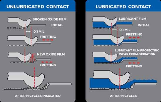
Fretting is typically caused by vibrations in a system or by temperature cycles and variations that cause expansion and contraction. As fretting occurs in a system, pressure can force a terminal through the contact surface to cause wear. As time goes on, the wear oxidizes and hardens the surface. Because of the small amplitude vibrations, particles of oxidized wear material have difficulty escaping from the contact zone where they continue to cause additional wear and oxides. As this wear happens and oxides form, the contact resistance in the terminal increases until continuity is lost. Figure 1 shows a kinetic model of fretting wear and corrosion.
Figure 1: Kinetic Model of Fretting Wear and Oxidation
In a lubricated contact, the lubricant provides a film that separates the moving surfaces and carries the wear particles out of the contact to help prevent additional wear and oxidation.
The general research into fretting wear that has been performed and published over the years heavily focused on bearings and power train applications [2]. The ASTM D4170 method “Standard Test Method for Fretting Wear Protection by Lubricating Greases” was the main method of evaluation used for much of that research [3]. D4170 evaluates the ability of lubricating greases to protect an oscillating bearing from fretting wear and differentiates the performance of formulated lubricants. Additionally, work was done around the proper formulation of a lubricating grease for performance in D4170 [4] [5] [6] and tied to the development of high-performance wheel bearing greases and their specifications [7] [8].
It is estimated that over 60% of the electric problems in cars are caused directly by fretting, and this problem could increase in the future with the expanded use of EHV’s [9] [10]. Because of this trend, fretting wear is one of the major mechanical forms of deterioration and failure of electrical terminals and contacts. There are many well-known applications where connectors are mounted to an engine, exhaust system, etc., and vibrations, as well as extreme temperature cycles, occur when the engine runs. In underhood applications, exhaust gases can accelerate fretting corrosion. All of these factors combine to make a very complex problem that leads to lowered reliability and possible warranty issues.
To improve the durability and reliability of automotive components under fretting conditions, lubricants are known to help extend the operational life of the contacts. This is accomplished in several ways. First, the lubricant helps reduce friction by forming a thin film between mating surfaces, which leads to an ease of sliding surfaces. Second, lubricants help seal porous coatings in electrical terminals where substrates such as copper can ‘bloom up’ through porous metals such as gold and cause advanced fretting corrosion. Finally, lubricants help protect against oxidation corrosion by insulating the lubricated contacts from the environment, which prevents oxide formation and more aggressive wear.
The study of fretting behavior of electrical terminals has been heavily researched [11] [12] [13] [14]. The fretting wear of various automotive components, including electrical terminals and connectors, has been studied at the research level and by commercial manufacturers. Their research showed that currently, fretting testing is being done with computer simulations, experimental simulations using bench tests and generic specimens (crossed cylinders, cylinder on plates, etc.) [15] [16], and electrical terminals subjected one at a time to mechanical vibrations or heat cycling.
The experimental simulation approach using generic test specimens has two main weaknesses. First, this approach uses a very small set of specimens, which makes it difficult to show statistical significance. Second, the geometry of the specimens can produce results that do not correlate well to commercial mechanisms. This has led to the development of the multi-terminal fretter (MTF) [17], which can evaluate as many as ten electrically isolated terminals at the same time for statistical significance. The design for the MTF is shown in Figure 2.
Experiments Testing Methodology
The MTF is made up of two electrically isolated testing blocks, one stationary and one oscillating. Various components are fixtured to these blocks for testing. A power source is applied, and a four-wire resistance measurement taken across the testing specimen. Once a test specimen is fixtured on the testing blocks, a linear actuator with absolute encoder is used to oscillate the testing stage and create the fretting wear testing profile. The frequency of oscillations is controlled by a voice coil actuator that allows for accurate motion control down to 1 µm over the fretting range. This operates on the principle of a magnetic field around a coil winding to generate a force (Lorentz Force) when current is applied to the coil.
When a test is fixtured and set up, great care is taken for the alignment of the components, specifically electrical terminals, to prevent issues caused by misalignment. A typical test is performed by first measuring the static resistance of the fixtured sample, and then continuously reading the 4-wire resistance until the failure criterion is met or the preset number of test cycles is exceeded. As the MTF can run multiple samples at the same time, the test continues until all samples fail. Typically, a 100 to 500 mΩ change in contact resistance constitutes a failure. This has been accepted as a representative failure level by the automotive industry [15] [17] [18].
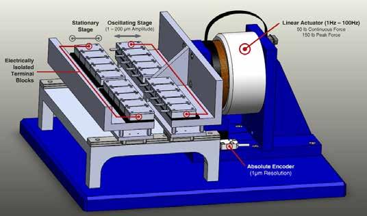
Figure 2. Multiple-Terminal Fretter Apparatus
Test Configurations
In this study, electrical terminals were tested in three different styles with low and high frequency oscillations and unlubricated and lubricated contacts. All testing was performed in an environment of 23 +/- 2 C and 40 +/- 5% relative humidity.
i. 2.8 mm beryllium copper electrical terminals ii. Completed electrical connectors using 1.5 mm terminals and receptacles iii. 1.5 mm electrical terminals used in the completed connector package
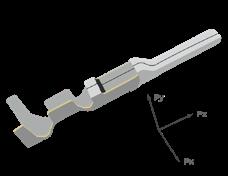
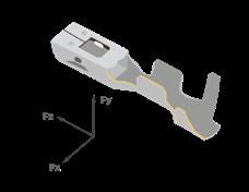
Figure 3. 2.8 mm Terminals
Figure 4. Completed Electrical Connectors
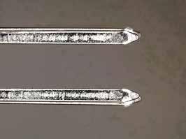
Figure 5: 1.5 mm Electrical Terminals
Two different testing plans were used in this study. The first plan focused on testing bare 2.8 mm beryllium copper electrical terminals. The second plan used fully assembled electrical connector packages for automotive heat controller applications, as well as the individual terminals, to simulate a finished assembly and the straight subcomponent terminals. The conditions for these simulations were 10 µm amplitude oscillations at 10 Hz (low frequency test) as well as 10 µm amplitude oscillations at 100 Hz (high frequency test).
Before testing, the electrical terminals were cleaned ultrasonically in mineral spirits followed by acetone. The testing apparatus was then assembled with 0.2 mg of lubricant added to the female terminal. For dispersion testing, the male terminal was dipped. Careful attention was paid to the alignment of the terminals, and then, the testing fixture was secured.
Testing was run at an ambient temperature of 23 C and 40% relative humidity, with no external load apart from the spring in the electrical terminal design. The testing was then performed with 10 cycles of coupling/uncoupling of the terminal pair to precondition the materials. After the precondition step, the test was static for 1 min while the baseline resistance was measured. Resistance readings were taken every 1 s with up to 10 readings on each channel. Then, oscillations at the test frequency and amplitude were performed until the average resistance over a 30 s period increased by more than 500 mΩ, which indicated a loss of continuity and failure due to fretting corrosion.
Materials
Two materials were tested in this study: i. Polyurea thickened grease based on a PAO/alkylated naphthalene oil blend of 193 cSt at 40 C ii. A 20% dispersion of the above grease in isoparaffinic solvent.
Analysis Software
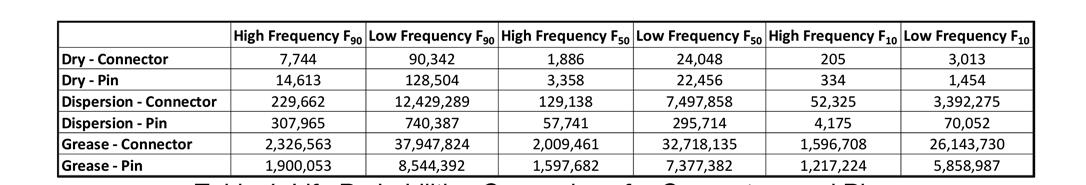
Minitab statistical software was used to calculate Weibull life probabilities from test data [6]. In general, a large number of samples is required to accurately estimate Weibull parameters. In this study, each evaluation had between 10 and 20 replicates to provide a large enough sample set of failure data to estimate the Weibull life probability. The mean, median, and 90% confidence intervals were calculated for all of the Weibull parameters and converted to life percentiles. The F90, F50, and F10 values were calculated; they represented the number of cycles until 90, 50, and 10% of the component population failed. The F50 value was used to represent lubricant life [19].
Results and Discussion 2.8 mm Fretting Tests
The results in Table 1 and Figures 6 and 7 are for the 2.8 mm terminals in the high and low frequency tests for both dry and lubricated conditions. These Weibull life probability plots illustrate that the grease significantly improved the durability of these electrical terminals versus the unlubricated contacts for both high and low frequency oscillations.
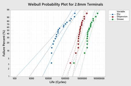
Figure 6. 2.8 mm High Frequency Fretting Results
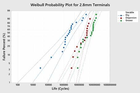
Figure 7. 2.8 mm Low Frequency Fretting Results
Figures 6 and 7 also show the results for the 2.8 mm terminals lubricated with a 20% dispersion of the grease in isoparaffinic solvent. While the 20% dispersion of grease in solvent did provide some improvement in life of the electrical terminals, it was significantly less improvement than the effect of the grease at both high and low frequencies. The reason for this difference in performance was based on the film thickness and amount of lubricant available to replenish the contact and protect the surface. When the lubricant was only 20% grease dispersed in a solvent, its oils and additives were depleted much sooner than in the case of the undiluted grease. Thus, the dispersion of grease in solvent was less successful than the grease at sealing the surface of the contact.
Connector Package Fretting tests
The results in Table 2 and Figures 8 and 9 are for the fully assembled connector package terminals tested at high and low frequencies for both dry and lubricated conditions. These Weibull probability plots illustrate that the grease and the 20% dispersion of grease provided a significant increase in the durability of the electrical terminals over the performance of unlubricated terminals under both high and low frequency conditions.
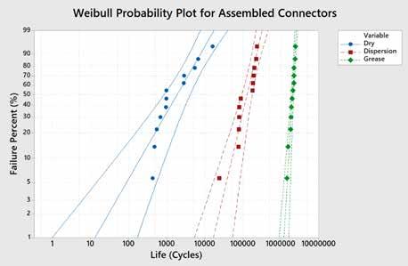
Figure 8. Assembled Connector High Frequency Fretting Results
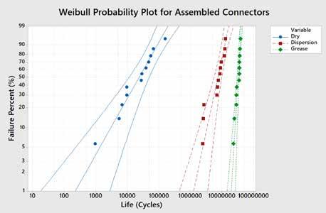
Table 2. Weibull Life Probabilities for Assembled Connectors
1.5 mm Terminals from Connector Package Fretting tests
The results in Table 3 and Figures 10 and 11 are for the terminals tested by themselves (not in connector packages). These Weibull probability plots illustrate that the grease and the 20% dispersion of grease provided a significant increase in the durability of the electrical terminals over the performance of unlubricated terminals under both high and low frequency conditions.
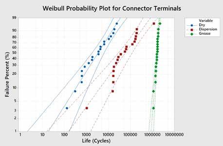
Figure 10. Assembled Connector High Frequency Fretting Results
Figure 11. Assembled Connector Low Frequency Fretting Results
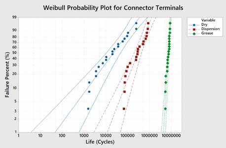
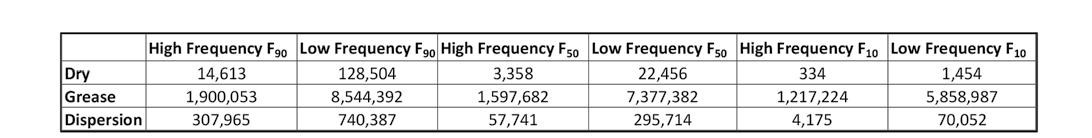
Table 3. Life Probabilities for 1.5 mm Connector Pins
Discussion
The results of these three fretting experiments indicated that lubrication improved the reliability and durability of the electrical contacts. This improvement in life expectancy of the lubricated contacts can be attributed to several factors: i. Ability of the lubricant or additive package to prevent oxidation corrosion. ii. Reduction of wear in the contact
Through passivation of surface oxides and removal of fresh nascent metal wear particles from contacts, the severity of abrasive wear was greatly reduced, as seen in Figures 12-15. The contacts tested with grease had the longest life probability and the least amount of wear.
The greased samples performed the best in this study, as these greases contained additives for passivation of metals and protection of the contact surfaces. In the case of the dispersions of 20% grease in solvent, the life and wear of contacts were improved over dry (no lubricant) samples, but contacts were still less durable than those lubricated with grease. As the dispersion only contained 20% of the lubricating grease, its additive package was depleted sooner, and there was no mobility of remaining lubricant as it was simply a thin film coating.
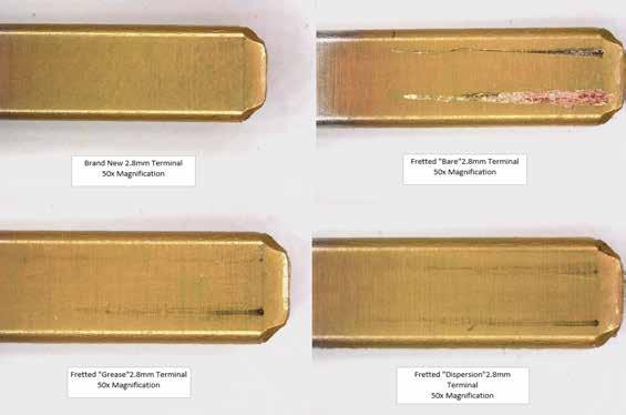
Figure 12. Wear of 2.8 mm Terminals (Low Frequency)
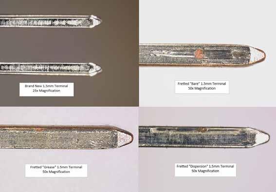
Figure 13. Wear of 1.5 mm Terminals (Low Frequency)
The wear patterns on the 2.8 mm terminals were very consistent, while the 1.5 mm pins showed a random placement of the wear scars (Figure 13). All of the wear patterns for these 2.8 mm pins always had a central circular wear track from the contact in the female receptacle along with a smaller track on either side. However, the 1.5 mm pin terminals all had random placement of this wear scar with combinations of centrally located wear scars along with scars on either side of the contact This random wear pattern occurred in the pre-assembled connectors and the individual 1.5 mm terminals.
After investigating this random wear pattern, it was found that the male and female receptacles for this connector package were not matched properly. Because of this mismatch, there was additional play in the package, which led to contact at random spots on the pin when mated. This illustrates a potentially serious issue, as the contract stress distributions differ on the center of the terminal versus the edge, which could lead to a larger amount of variation in the life of the electrical terminal. This observation emphasizes the importance of making sure that the components are properly matched. To investigate this further, surface topography using a profilometer was performed on several wear scars as seen in Figures 16 and 17.
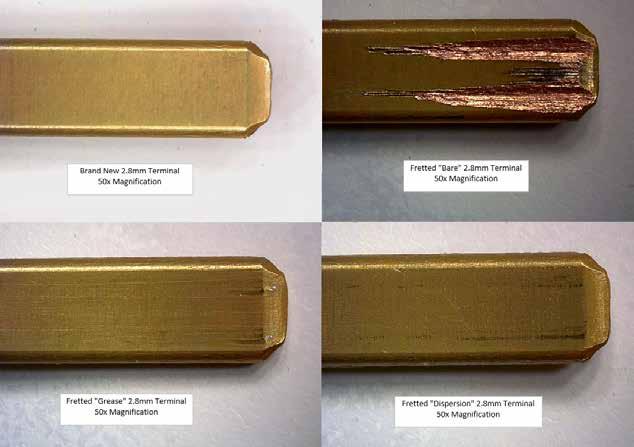
Figure 14. Wear of 2.8 mm Terminals (High Frequency)
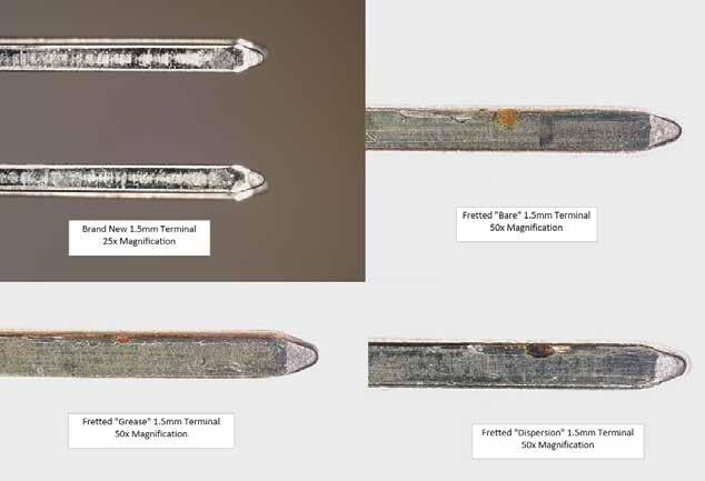
Figure 15. Wear of 1.5 mm Terminals (High Frequency)
The wear surface profiles shown in Figures 16 and 17 were acquired using a Taylor Hobson Talymap Profilometer. The color corresponds to depth in each surface profile. Profiles were taken from several 1.5 mm terminals used in this testing to further investigate the concerns about contact stress distribution related to the random placement of wear scars. On terminals that had wear scars along their edge, the average wear volume lost was 70,500 µm3, while the centered scars were under 9,000 µm3. This dramatic difference in wear volume was attributed to a smaller area of contact with the mating terminal, which resulted in higher contact stress and larger wear volume.
Figure 16. Surface Wear Topography (Edge Scars)
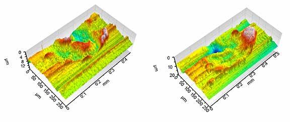
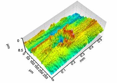
Figure 17. Surface Wear Topography (Center Scars)
Comparing results from all three experiments shows that these results all follow the same trend for performance. The lifetimes for completed connectors lubricated with grease were much greater than either of the straight terminal tests.
Looking at the assembled connectors after these tests, two discoveries were made. First, there was a significant degree of freedom in the overall movement of components. This allowed for the energy put into the connector through the fretting motion to be absorbed or redirected. Because of this reduction in the relative friction, lifetimes of the assembled connectors are expected to be significantly greater than the pins and sockets by themselves. (This initially drove the third experiment.)
Second, the manufacturer of this automotive component used non-matching pins/sockets. This discovery clearly illustrates the need to exercise great caution when selecting non-matching components. In this case, the contact stress in the terminals was outside the desired range, which led to increased wear rates. These fitment issues and contact stress differences can also lead to uneven wear of contacts, which by itself can lead to discontinuity (failure) of contact resistance and application failure.
Conclusions
This study used a variable frequency multi-terminal fretting (MTF) tester to evaluate component level electrical terminals and completed connector assemblies, and the effects of dielectric lubricants on reliability and durability of these components. The use of a dielectric lubricant (grease or dispersion of grease in solvent) greatly improved the durability of the electrical terminals and connectors.
For the 2.8 mm terminals, the durability was increased by ~24 times in the high frequency testing (100 Hz) and 7 times in the lower frequency tests (10 Hz). This life improvement was directly tied to the reduction of oxide formation in the electrical contact, which drives the amount of abrasive particles produced.
While the overall life of the electrical contact was better at low frequencies, the durability improvement over dry unlubricated contacts was greater with the high frequency than low frequency testing. This difference was related to sliding speed in the contact and how the lubricant film formed. As the speed increased in a contact, a strong EHD film was created, separating the surfaces and pushing the particles out of the contact.
The assembled connectors, as well as the separate 1.5 mm pins and sockets, showed similar results but with much greater increase in durability compared to dry terminals. In these tests, the improvement from the pin/socket tests to the connector assemblies ranged from 2 to 11 times the durability in the life of the test. The improvements seen in the connector assembly testing were due in part to the fitting and amount of free body motion allowed in the connector, which helped to redistribute the force, reduce fretting, and allow for a longer test life. While this may be the case with all connector assemblies, this differential between the electrical terminals and assembled connectors is believed to be on the lower side of the range.
From the results of this study, there was a significant improvement in durability and reliability of electrical terminals when a connector lubricant was used. Using the MTF test rig, similar performance results were seen when testing terminals, fully assembled connector housings, and the electrical terminals from those connectors. This is a critical point, as it illustrates that when using the MTF, an accurate experimental simulation of applications can be made using only the electrical terminals, which will save time, costs, and test complexity.
It is also important to note the following findings from this study: i. All connector lubricants are not the same. An oil or dispersion of grease will not protect the electrical contact as well as a properly formulated dielectric grease.
ii. An increase in frequency can reduce the time until the onset of fretting corrosion and reduce the durability of the contact.
Acknowledgements
I would like to thank the ADVT team at Nye Lubricants, specifically Gus Flaherty, Richard Bellizzi, and Mason Wood, for performing the testing and fabricating testing fixtures.
References
[1] Bolger, G. “The selection of automotive connectors”, Senior Thesis, Coventry University., U.K., 1997. [2] Law, D. A. and Rowe, C. N., “Fretting Wear with Powertrain Lubricants,” Lubrication Engineering, 43 (8): 616-622 (1986). [3] Verdura, T. M., “Development of a Standard Test to Evaluate Fretting Protection Quality of Lubricating Grease,” The NLGI Spokesman, 47: 157–67, (1983). [4] Schlobohm, R. T., “Formulating Greases to Minimize Fretting Corrosion,” The NLGI Spokesman, 45: 334-338, (1982). [5] Wunsch, F. G., “Relationship between the Chemical Structure of a Lubricant and Fretting Corrosion,” The NLGI Spokesman, 52:. 424-31, (1988). [6] Kaperick, J. P., “Fretting Wear – Something to Worry About?,” The NLGI Spokesman, 72 (4):. 19-29, (2008). [7] Kato, M. and Sato, T. “The Development of Low Friction and Anti-Fretting Corrosion Greases for CVJ and Wheel Bearing Applications,” SAE Technical Paper Series 871985 (1987) [8] Mishima, M., Kinoshita, H., and Sekiya, M. “Prevention of Fretting Corrosion to Wheel Bearings by Urea Grease,” The NLGI Spokesman, 53: 496-504, (1990). [9] Swingler, J. and McBride, J. W. (1998) The synergistic relationship of stresses in the automotive connector. Proceedings of the 19th International Conference on Electric Contact Phenomena. 01 Jan 1998. pp. 141-145 . [10] Swingler, J., McBride, J. W., and Maul, C. “Degradation of road tested automotive connectors.” IEEE Transactions on Components and Packaging Technologies, 23 (1): 157-164, (2000). [11] Hannel, S., et al. “The fretting sliding transition as a criterion for electrical contact performance.” Wear 249.9: 761-770, (2001) . [12] Achanta, S., et al. “Friction mechanisms at the micro-scale.” Tribology International 42.11-12: 1792-1799, (2009) . [13] Saka, N., Liou, M. J., and Suh, N. P. “The role of tribology in electrical contact phenomena.” Wear 100.1-3: 77-105 (1984). [14] Chowdhury, M. A. and Helali, M. M. “The effect of frequency of vibration and humidity on the wear rate.” Wear 262.1-2: 198-203, (2007). [15] Liskiewicz, T., Neville, A., and Achanta, S. “Impact of corrosion on fretting damage of electrical contacts.” Electrical contacts-2006, Proceedings of the Fifty-Second IEEE Holm Conference on. IEEE, (2006). [16] Achanta, S. and D. Drees. “Effect of lubrication on fretting wear and durability of gold coated electrical contacts under high frequency vibrations.” TribologyMaterials, Surfaces & Interfaces 2.1: 57-63, (2008). [17] Galary, J. “Investigation of Fretting Wear and Durability of Electrical Terminals when exposed to Variable Frequency Vibration”. JAST Transactions of the World Tribology Conference, (2015). [18] SAE/USCAR. “Performance Specification for Automotive Electrical Connector Systems” SAE/ USCAR-2, (2013). [19] Weibull, W. “A statistical distribution function of wide applicability.” Journal of Applied Mechanics, 18.3 : 293-297, (1951).


