28 minute read
The Cost of Compromise: Wind Turbine Main Shaft Grease Lubrication Engineering Study


Edward Worthington and Dwaine Morris Shell Product Technology Hamburg, Germany and Houston, Texas, US
Abstract
Wind turbine main shaft and blade bearings have divergent lubrication requirements due to some specific application conditions and performance implications. Main shaft bearings are heavily loaded components subjected to slow rotational speeds, shock loads and variable ambient temperatures. While blade bearings are also subjected to similar conditions relative to load and temperature, they are further exposed to limited angle of rotation and are prone to fretting wear due to high frequency vibrations. To satisfy lubricating requirements, most main shaft greases tend to contain higher viscosity base oils, whereas blade bearing greases have trended toward lighter viscosity base fluids. However, there have been, and continue to be, attempts by original equipment manufacturers and turbine owners to utilize the same lubricating grease for these divergent applications. Wind turbine original equipment manufacturers are increasing base oil viscosity for blade bearing greases while simultaneously decreasing the base oil viscosities of main shaft greases. Their intents are to gain mobility and reduce low-temperature torque in the main shaft grease, while increasing the shock load resistance of the blade bearing grease and maintaining the fretting wear protection. For the OEMs and maintenance service providers, this consolidation reduces complexity. However, this consolidation compromises optimal performance in both applications.
This paper examines a case study of a specific attempt where consolidating greases for main shaft and blade bearings led to excessive wear and risk of catastrophic wind turbine failure. The analytical tools and engineering calculations used in a root cause analysis in this case study can also be applied to predict the suitability of greases for main shaft bearings and other applications.
Presented at the NLGI 85th Annual Meeting Coeur d’Alene, ID June 9 - 12, 2018
Background- Renewables on the Rise
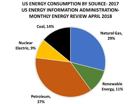
Wind energy is growing in significance in the US energy production market. According to the American Wind Energy Association (AWEA): • In 2012 wind energy became the number one source of new US electricity generating capacity, supplying 42% of the newly installed capacity. [1] • The turbines themselves are producing nearly 20 times more power per turbine than those installed in 1990. [2] • Together, renewables accounted for ~67% of newly installed power generation capacity in the US in 2015. [2] • In 2016, electricity generated from wind energy avoided 159 million metric tons of carbon dioxide emissions. This is the equivalent of reducing power sector CO2 emissions by 9% and avoiding the consumption of 87 billion gallons of water. [2]
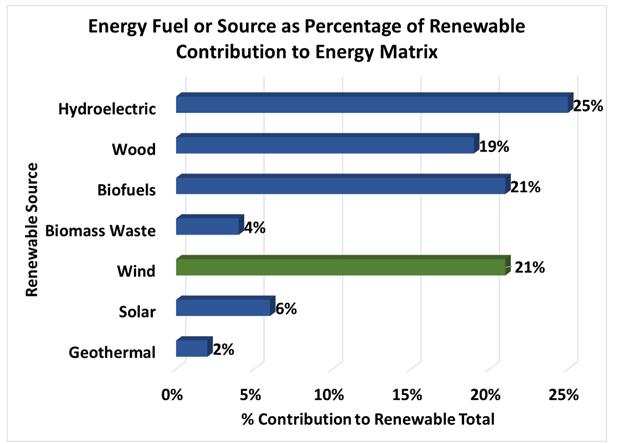
Figure 1 US Energy consumption sources- 2017 and Renewable detail
According to updated information from these same sources, wind power (Wind) now contributes over 6% of the US power generation capacity. In addition, for the most recent 5-year period (2013-2017) Wind accounts for 25% of the annual newly installed power capacity additions.
As Wind becomes more prominent in newly installed capacity of the North American energy production matrix, its reliability becomes more critical as other portions of the energy portfolio begin to decline. As coal has waned as an electrical generation fuel, the contribution of ‘other renewables’ (Figure 1) and natural gas are expanding to close the demand gap. [3] As Wind becomes more prominent in the newly installed capacity, the longevity and reliability of wind turbine assets must be ensured.
Setting aside all other challenges to operational efficiency in the turbine, reliability and operational availability for the blade and main shaft bearings must be considered as critical path. These two distinct applications have some common lubrication needs, but the primary failure modes are significantly different enough to warrant the application of unique grease solutions per application. Wind original equipment manufacturers (OEMs) have been migrating to grease consolidation to simplify manufacturing and installation. In addition, this reduces complexity for them during the period in which they are responsible for the upkeep of the ‘new’ turbines.
In general, consolidation of products may appear to be a valid or even a good option, but in the case of wind turbine bearings, careful consideration of operational conditions and examination of potential outcomes provide more than enough reasons to pause and reconsider that approach.
The following case study is an example illustrating that collective lubrication shared experience and engineering knowledge are more than adequate to provide a warning of potential negative outcomes from selection of an inappropriate lubricant. In this case study, the calculations predicted bearing distress in the applications. The long-term, real-world outcome verified these calculations. This case in particular should serve as a warning to OEMs and operators alike to exercise caution in the selection of lubricating greases for the main shaft grease.
Due to confidentiality concerns for the OEM and the wind farm owner / operator, the identity of those parties is withheld from this paper. In addition, the geographic location of the facility is not disclosed for the same reasons. Historic ambient operating conditions are shared to illustrate the importance of selecting greases to prevent, or at a minimum, mitigate, damage before widespread failures become imminent.
Introduction
From location to location and fleet to fleet, main shaft bearings in wind turbines operate in a wide variety of environments. Ambient temperatures can range from -30 to 45 C . The rotational speeds hover in the range of 10-20 rpm during the generation cycle. The bearings experience shock loading, vibrations and heavy loads (C/P ratios from ~6 to 8). These conditions determine the requisite size and bearing design necessary to manage the shock and thrust loading. These same considerations should determine the correct grease selection.
Due to confidentiality concerns of all parties, the exact bearing will not be discussed, but an analog double row spherical roller bearing is put forward for consideration with the following dimensions and load limits:
Bearing ID 560 mm Bearing OD 820 mm Bearing Width 195 mm Dynamic Load Rating 5,600 kN Static Load Rating 10,200 kN [4]
Based on the above design and load specifications, available calculation tools indicated that the minimum viscosity required at the bearing operating temperature to maintain a Kappa value (viscosity ratio) >1.0 is 143 cSt. The Kappa value is defined as the ratio of the viscosity of the lubricating grease film divided by the minimum required viscosity at the bearing operational temperature. In this case study, the installed grease was an ISO 150, NLGI 1 lithium thickened grease fortified with extreme pressure additives. A cursory review would indicate that this grease would be acceptable for the normal operation of the main shaft bearing with a nominal Kappa value >1.0 at bearing temperatures up to ~42 C.
After approximately 9 years of operation, main shaft bearing in-service grease samples contained high concentrations of wear metals. Consultation with lubricant suppliers verified that less than adequate fluid film was a major contributing factor in the excessive wear. The OEM and maintenance operations at the site instituted a mitigation plan that was intended to flush the wear debris and install a grease with higher viscosity base fluids.
The maintenance program was not completely successful, and recent analysis of the in-service greases indicated an approximate 50/50 ratio of the fill grease and the mitigating grease (a synthetic ISO 460 polyurea thickened grease with extreme pressure additives). Wear metal analysis revealed copper in the range of 65,000 ppm and iron content in the range of 28,000 ppm. Wear metal species present in these quantities are indicative of significant cage and roller wear. These results are consistent with the expectations of bearing distress when the bearing is operating with Kappa values less than 1.0 or in lubrication starvation mode.
The presence of high concentrations of wear metals was also catalyzing the oxidation of the in-service grease. Pressure differential calorimetry indicated no reserve oxidative life for the in-service grease. If allowed to continue in this condition, catastrophic failure was more than a possibility. A slow-motion disaster was a forgone conclusion, predicated on dubious assumptions and operational conditions that exceeded the performance limits of the installed grease in the main shaft bearing.
Grease Selection Considerations
The primary consideration for grease selection should be viscosity (and the corresponding lubricating film) at the bearing operating temperature. Care should always be taken to ensure that the chosen lubricating grease provides an adequate fluid film under extreme conditions as much as possible, but performance under the ‘anticipated normal’ conditions is essential. The primary failure modes, and the ability of the grease to mitigate those, are an important secondary concern.
In the case of main shaft bearing greases, the major performance demands for the grease are load carrying capacity (EP and AW under loaded conditions), mechanical stability, oxidative resistance, mobility (in bearings and central lubrication systems), minimal starting / running torque and corrosion control. A secondary concern is fretting when the turbines are idle. In the case of a blade bearing greases, performance demands are nearly identical, except that fretting corrosion control is significantly more important due to the high frequency vibrations that can cause significant damage and failure in blade bearings.
It is easy to understand the urge to consolidate lubricating grease products for these two applications, as these applications share so many common lubricating needs / challenges; however, consolidation can be dangerous.
Within the wind industry, OEMs have developed test matrices that mimic the primary failure modes of bearings. These test regimes include some standard tests (Fafnir Fretting - ASTM D4170) and some wind specific tests, such as the impact fretting test and the Riffel test. [4] [5] [6] Each of the OEMs leans on their
According to Yano, there are relationships between fretting and load carrying capacity as measured by the specialized load carrying tests (Impact Fretting). [4]
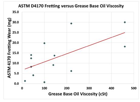
Figure 2 Fretting wear in ASTM D4170 versus viscosity for selected grease products
Figure 2 illustrates relative wear performance in ASTM D4170 of selected greases from the Yano study. As viscosity increases, the ability of the product to protect the bearing from fretting wear decreases.
In any population of greases, as in the Yano study, there is scatter regarding fretting wear. This scatter in test data is directly related to oil release properties of these products, and the oil release properties account for the variation in performance of products with nearly identical viscosity with regard to fretting.
The importance of this general relationship between fretting wear and base oil viscosity hints at the OEM decision process when selecting the main shaft grease. It appears that the OEMs have been concerned about the secondary failure mode of fretting in the main shaft when they specified the main shaft bearing grease.
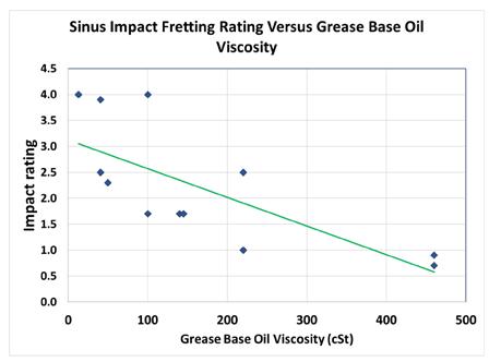
Figure 3 Impact fretting rating versus viscosity for selected products- lower ratings indicate better protection / performance in the test
Yano observed that protection from impact fretting (related to load carrying) increased as oil viscosity increased (Figure 3), which is the inverse of the trend that protection from fretting wear decreased as oil viscosity increased (Figure 2).
Figure 4 shows that there is an inverse relationship between impact rating (load carrying) and fretting wear for greases. To have the required load carrying capacity (related to the viscosity), grease formulators must trade off between these two performance characteristics. Thus, using the same grease in main shaft bearings (where load carrying is a priority) and blade bearings (where fretting resistance is a priority) comes with an inherent compromise.
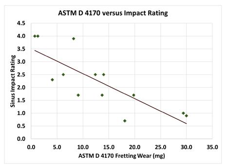
Figure 4 The ASTM D4170 performance of selected greases plotted against their corresponding impact rating
If the intent is to choose a single, consolidated grease product, a logical approach would be to identify a product that would meet the primary performance requirements related to viscosity and load carrying capacity, while maximizing fretting protection. By selecting a product that has oil release properties and bearing mobility that provide some level of fretting protection, it might be possible to find a consolidated grease solution.
Figure 5 shows a plot of ASTM D4170 fretting wear on the primary axis and impact rating on the secondary axis versus base oil viscosity for a set of grease products. From this plot, it is possible to identify those products that are theoretically capable of achieving adequate performance in both screening tests. The logarithmic trend lines for the two sets of test data cross at approximately ISO 150. The region where the lines intersect indicates products with the potential for compromise with ‘middle of the road’ performance in both measures. Recall that the calculated minimum required viscosity for the main shaft bearing is 143 cSt.
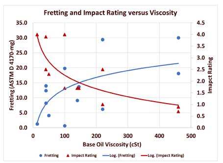
Figure 5 Fretting wear and Impact rating plot versus viscosity, looking for a compromise product. Red line indicates impact rating while the blue line indicates fretting wear
The authors are not privy to the thought process specifically, but this seems to be a logical progression given the openly available performance information and literature on the subjects.
However, the specific performance issue related to this installed fleet was due to the assumption of bearing operating temperature. If the assumptions were that the bearings would not exceed 40 C, then the location and historical ambient temperature data should have been checked and verified.
During the analysis phase of the product selection process, it is important to establish the estimated bearing temperatures to project the efficacy of the chosen product for the fleet location. Once the authors were contacted to conduct the failure analysis and mitigation for the site, the first step was to determine the required viscosity for the operating bearings and then determine what the projected operational bearing temperatures would be under normal and extreme circumstances. Consider the following:
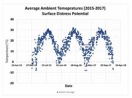
Historical ambient temperature for the site from 2015-2017 in Figure 6 revealed that the average temperature did not exceed the limit of the chosen grease (42 C) to provide adequate fluid film for the bearing. However, the bearing temperatures would be elevated above the projected average for an extended amount of time based on loading and the fact that the high temperatures would considerably exceed the average. In fact, the analysis in Figure 7 confirmed this:
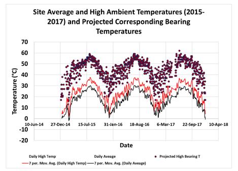
Figure 7 Moving average temperature, daily high temperature and the projected daily high bearing temperature
The projected daily high bearing temperatures, based on ambient +20 C, would ensure that the bearing would be operating a significant portion of the time in a region of surface distress based on the installed grease’s published base oil viscosity and its projected response to temperature, Figure 8:
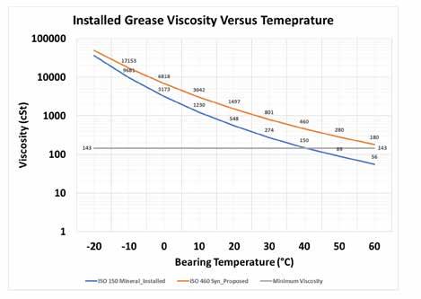
Figure 8 Projected viscosity of installed grease and an ISO 460 synthetic grease as bearing temperature rises
Based on loading, the calculated projected bearing temperatures corresponding to the temperature estimates plotted in Figure 7, with the average operating temperature of the bearing at 25 C ambient was 52 C, exceeded the limits of the installed grease to provide adequate film for the operation. The average daily high temperature over the three-year period from 2015 to 2017 was 24.4 C. This would invalidate the assumption that, the bearing operating temperature is less than 42 C, Figures 7 and 9.
Feedback from the site confirmed that recorded bearing temperatures aligned with the projected and calculated values. The resultant viscosity of the installed grease ensured that the bearings were operating where their surfaces would be distressed on approximately 60% of the days (~220 days per year), and even at the lowest ambients, the bearing operational temperatures would be in excess of the performance limit of the installed grease ~50% of the time, Figure 9.
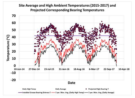
Figure 9 View of projected bearing temperature and the distress point of the installed grease The previous analysis is predicated on the steady state assumption, meaning that the turbine shaft is rotating at a constant speed. The actual reality is much different, with start / stop and potential low wind velocity situations. Even though the physical dimensions of the bearing and surface finish are the same as rotational speed changes, the required viscosity to maintain Kappa values >1.0 changes as well. As speed increases, the viscosity required to maintain a Kappa value >1.0 decreases. More importantly regarding lubrication of the main shaft bearing, as the speed slows, the required minimum viscosity increases, while there is no immediate change in the bearing temperature.
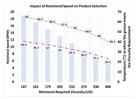
Consider the graphic below in Figure 10 where the columns show the viscosity required to provide adequate lubrication at the indicated rotational speed of the main shaft (primary vertical axis). This is an absolute viscosity required at any temperature based on the bearing rotational speed regardless of bearing temperature. At the highest rotational speed of 19 rpm, on the left, the viscosity required is the lowest (147 cSt). By the same token, the slowest rotational speed of 5 rpm requires the highest viscosity (448 cSt).
As the bearing temperature increases, due to load and/or ambient conditions, the viscosity of the fluid in the grease goes down. The red line represents the temperature (in C) at which the installed grease provides the requisite film (secondary vertical axis in Figure 10). Any time the bearing temperature exceeds the red line at the indicated rotational speed, the fluid film of the installed grease is inadequate.
For example, at 5 rpm, the bearing requires a product with a viscosity of 448 cSt at the operational temperature. The installed grease (red line) can provide a film of 448 cSt only up to a bearing temperature of 23.1 C. The operational implication is that, given a speed of 5 rpm, if the bearing temperature is
above 23 C, the Kappa value drops significantly below 1.0 and the bearing is in the distress zone at
that speed. This is true for the intended operational speed of the main shaft, where the bearing will be in distress any time the bearing temperature exceeds the ability of the grease to provide the requisite film.
Figure 10 Effect of rotational speed on an applicable, fit for purpose product The base of the red arrow in the modified graphic in Figure 11 indicates that in the best-case scenario, where the main shaft is in steady state and the bearing temperature is within an acceptable range for the installed grease, a decrease in shaft speed from 19 down to 5 rpm pushed the viscosity requirement up, while the bearing’s operating temperature remained unchanged. The fluid film is insufficient at that point (tip of the arrow is significantly above the dashed red line of the installed grease at 5 rpm. The viscosity of the film is ~1/3 of the required, leading to increased metal to metal contact and catastrophic wear.
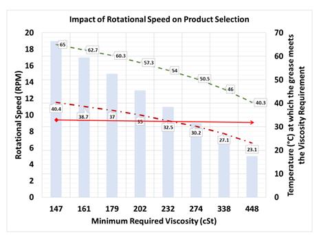
Contrast that with a synthetic ISO 460 grease that will provide a sufficient film at 40.3 C in the 5 rpm scenario. The dashed green line illustrates the corresponding relationship between bearing temperature and viscosity for a synthetic ISO 460 grease in the same set of circumstances. The gap between the two lines is the temperature window, all along the speed curve, where one product is fit for purpose and the other is not.
During low wind velocity conditions, while the bearing temperature was elevated, the film of the installed grease was insufficient to maintain adequate separation of the bearing components. The obvious consequence was that elevated bearing temperatures combined with low wind velocity further placed the bearing in distress.
On the other hand, at all speeds from 5 to 19 rpm, and bearing temperatures from 40 to 63 C, an ISO 460 grease would have the requisite film to protect the bearing. The film of the installed grease would be
inadequate any time the bearing temperature exceeded 42 C.
Another way to view the conditions is to compare Kappa charts where rotational speed and temperature can be varied relative to each other, and the Kappa value is designated by color in Figure 12:
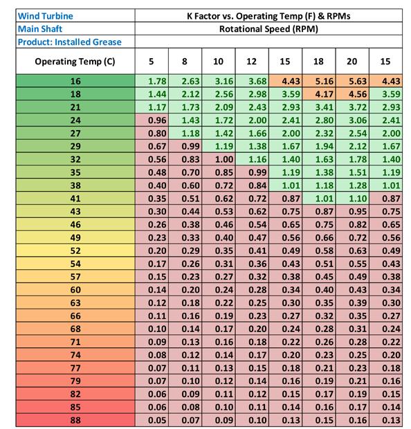
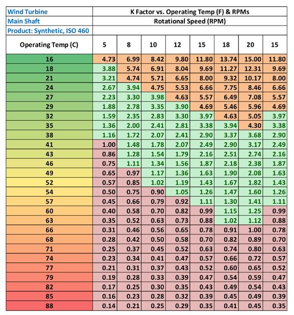
Figure 12 Kappa charts for the installed ISO 150 grease (top) and a synthetic, ISO 460 alternative grease as speed and temperature vary
On the top is the Kappa chart for the installed grease, and the alternative synthetic, ISO 460 is on the bottom of Figure 12. These charts show the effect of rising bearing operating temperature from 16 (top) to 88 C (bottom) on Kappa. Across the chart from left to right, the rotational speed of the bearing increases from 5 to 20 rpm. The last column is an ‘average speed’ of 15 rpm. The regions of orange and green indicate adequate bearing lubrication where the Kappa ratio is greater than 1.0. The red is indicative of distress, where Kappa values are less than 1.0. The further down the rotational speed column, the more the Kappa value deviates from the minimum acceptable value of 1.0. This ignores any shock loading during operation, which would increase the surface contact and potential for surface damage.
Viewing the main shaft grease selection from a steady-state, best case scenario indicates that the installed grease was fit for purpose only up to 43 C as indicated. Considering the varying wind speed scenario, in conjunction with the historical ambient temperature information, the selection of the ISO 150 grease is cast in an even worse light.
Operational Impact
Due to insufficient lubricating film, the bearings were operating a significant portion of the time in a region of the Stribeck curve where surface distress was inevitable. Since the theoretical / projected temperatures were in fact reality, as indicated by the site feedback, the resultant wear would be catastrophic. The wear metals present in the sampled in-service grease confirm the empirical projections and illustrate the extent of the damage experienced by the bearings in operation.
The loss of any reserve oxidative resistance would result as the wear metals catalyzed oxidation of the installed grease.
These anticipated results have been thoroughly documented. Wear metal results were previously discussed, but the visual inspections of the bearings left no doubt that the site was experiencing serious, catastrophic wear that projected to premature failure of the bearings.
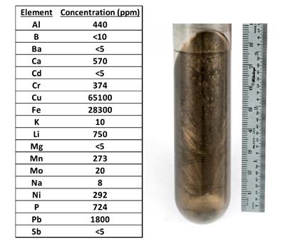
Figure 13 Wear metal scan (left) and visual of centrifuged in-service grease sample (right)
Figure 13 shows data from the analysis of wear metals in a sample of in-service grease. Metallic copper is visible as striations in the centrifuged grease sample. The iron levels exceeded 2.5% of the in-service sample, and the copper was also exceptionally high, indicating significant cage wear.
The bulk color of the used grease was black (the fresh grease was beige), illustrating the oxidized condition of the grease. Pressure Differential Scanning Calorimeter (PDSC) testing indicated that the inservice grease had little oxidative life left. Although, it should be noted, because of the high copper, iron and zinc content, these metals may have acted as catalysts during the analysis, possibly increasing the rates of oxidation reactions. In tests at 195 C and 500 psi (ASTM D5483), the induction time for in-service grease was less than 3% of the time for fresh grease.
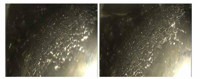
Figure 14 Inner race damage visible through borescope inspection of the bearing
The projected life of these bearings, under the operational conditions of speed and load is anticipated to be over twenty years where Kappa values are at least 1.0 and routine maintenance is observed (bearing lubricated regularly at appropriate intervals and free of contamination). Bearing manufacturers project bearing life based on loading condition and the capacity / design of the bearing via the life equation:
L10 = (C/P) p
Where: L10 is the rated life in hours with 90% reliability C is the basic dynamic load rating (kN) P is the operating equivalent dynamic load (kN) p is the exponent in the life equation (10/3 for roller bearings) Bearing application specific loading and operational information:
Radial Load 480 kN Axial Load 120 kN
Dynamic Load Rating 5,600 kN
Static Load Rating 10,200 kN [4] Ambient Temperature 0 to 40 C
The analog bearing used for the calculations has a dynamic load rating of 5,600 kN and the bearing load as indicated earlier is 480 kN radial and 120 kN axial. The equivalent dynamic load is calculated to be 874 kN via SKF calculation tools. [7] The load ratio is therefore 6.4 (5,600/874). The L10 in years, assuming adequate lubrication is ~50 years. [7] The fact that a statistically significant number of the fleet bearings were in failure mode at 9 years set off appropriate alarm bells. Consider the graphic in Figure 15:
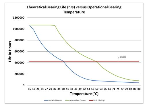
Figure 15 Theoretical bearing life, assuming adequate lubrication at 19 rpm versus bearing operating temperature
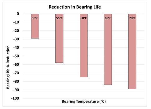
Figure 16 SKF calculated evaluation of the bearing under the same conditions, illustrating a mirror response of negative bearing life impact as temperatures rise
As stated previously, when bearing temperatures are at or below 42 C, the theoretical bearing life far exceeds the 20-year target (175,000 operational hours). However, the actual bearing temperatures based on historic weather data for the installation region significantly impacts the bearing life. In contrast, an ISO 460 synthetic grease would provide the same life expectancy at much higher bearing operational temperatures, up to 63 C.
Based on SKF calculation methodology, where the minimum required viscosity is slightly lower, the relative difference in bearing life expectancy is significant, with the installed grease only supporting a theoretical life that is ~25% of the theoretical life with an appropriate ISO 460 grease at a bearing temperature of 60 C.
Recall that historical weather for the region projected high bearing temperatures to be over 50C at least 33% of the time, and 56% of the time the bearings will exceed the distress point of the installed grease. If it was just as simple as the bearing responding to the ambient temperature changes, the effect on the bearing distress point could be minimized. However, the bearing temperature does not cool immediately, and the nacelle ambient often exceeds the outside ambient, reducing the delta T that could drive the heat transfer away from the bearing. If you consider the impact of variable speed on the viscosity required, as discussed earlier, the impact is potentially more dramatic.
Compounding the effects of temperature is the presence of wear metals in the bearing and grease itself. The wear metal particles oxidize the grease, but also can be large enough to bridge the already thin fluid film and cause point loading and fatigue in the bearing. This would compound the detrimental effect on the bearing performance and anticipated life.

In this case, main shaft bearings are manually lubricated twice per year, and the supply of fresh grease is not sufficient to flush away the wear particles and spent grease. Catastrophic failure is not a question of if, but merely how long before the bearing condition reaches the ‘point of no return’. The wearing away of the surfaces in the cage and assembly allows the bearing to shift axially in the housing as well, which causes more mechanical faults and heat, further exacerbating the conditions and hastening the impending failures.
Mitigation and Recommendations
The initial decisions have had a slow, progressive negative effect on the performance of the fleet. However, the pace of the bearing failure increases with all the mitigating and compounding
More Than Just a Drop in the Bucket
VANDERBILT CHEMICALS, LLC CERTIFIED TO ISO 9001:2015 10002461
MOLYVAN® 855
Friction Reducer
Today’s high performance lubricants require special additives to perform successfully. MOLYVAN® 855 is an organo-molybdenum additive that contains no phosphorus or sulfur and is more cost effective than traditional molybdenum dithiocarbamates. Lubricants formulated with MOLYVAN® 855 exhibit enhanced oxidation and wear protection, as well as reduced timing chain wear and improved low speed pre-ignition (LSPI) performance, two new requirements proposed for GF-6.
Order a sample and discover the many benefits of this unique additive component in your lubricant formulation.
petro@vanderbiltchemicals.com www.vanderbiltchemicals.com (203) 853-1400
30 Winfield Street, P.O. Box 5150, Norwalk, CT 06856-5150, USA
Registered and pending trademarks appearing in these materials are those of R.T. Vanderbilt Holding Company, Inc. or its respective wholly owned subsidiaries. For complete listings, please visit this location for trademarks, www.rtvanderbiltholding.com.
circumstances that are a result of the initial decision to apply a grease that was not fit for the operational conditions. The damage cannot be reversed, only mitigated using a fit for purpose grease that will minimize further wear through proper viscosity / adequate fluid film.
The grease selection must first address the viscosity of the film at the anticipated ambient and corresponding bearing temperatures. There is simply no substitute for providing a lubricating grease that can provide adequate fluid film thickness at the highest anticipated temperature (or at least the clear majority of the operational time). This must be balanced with the minimization of low temperature torque and lost bearing efficiency during the coldest ambient conditions.
Fleet operations management must evaluate the state of the fleet and prioritize the actions to mitigate the operational and financial impact. The economic impact of replacing one of the fleet main shaft bearings is approximately $300,000. The replacement of a bearing involves a loss of operational revenue, and a substantial health and safety risk to the workers tasked to install the new bearing. The wholesale replacement of the main shaft bearings across this farm would exceed $40MM. Fleet-wide bearing replacement is exceedingly expensive, and therefore it is prudent to perform ‘bearing triage’.
Bearing triage involves additional costs for analytical evaluation of the in-service grease and bearings. It also involves inspection costs above and beyond anticipated maintenance and operations budgets. These services also come with inherent health and safety concerns. The bearing replacements can be prioritized by the aggregate of loss of mechanical tolerances in the turbine drive train (the bearing is only part of the equation), the level and identity of wear metals present in sampled grease, and operational bearing temperature relative to the ambient conditions at site.
The wholesale change of the installed grease is the starting point. Close monitoring of the bearing assets after the change can further guide the site management on priorities regarding bearing replacement.
Conclusions
As more newly installed electrical generation capacity is supplied by wind turbine fleets, the asset health of critical path components of these fleets should be prioritized over convenience and simplification by OEMs and operational staff. Blade and main shaft bearings have some common lubrication needs, but their primary failure modes diverge. The formulary methods for addressing the diverging failure modes of the bearings in question are different enough to require careful consideration regarding grease selection for the applications. The most appropriate grease for each bearing application, most likely, will not be the same.
Grease selection, without careful consideration of the operational realities of bearing temperature and rotational speed, can lead to catastrophic, expensive failures and mitigation costs. The fact that the effects of grease selection are not immediately evident conceals the true cost and delays the expensive remediation expenses that then become the responsibility of the owner/ operator of the fleet. Most likely, the consequences of these decisions will materialize long after the warranty or service contract expires, leaving the owner responsible to absorb these unnecessary and avoidable expenses, along with loss of operating revenue and increased health and safety risks incurred to make the necessary repairs.
Paramount in the grease selection process should be viscosity at the anticipated operating temperature of the bearing. However, greases are complex systems of base oils, performance enhancing additives and thickeners. These components play an important role in the ultimate performance of the chosen product in the specific application. Understanding the application needs and overlaying the performance of candidate greases in efforts to mitigate failure modes is the secondary step in the process.
Asset health and reliability of the turbine should be placed ahead of any compromise on product selection. Grease selection should be based on available data, not conjecture, anecdotal stories and hope. Industry available tools can accurately predict lubrication related outcomes as illustrated by this case study. These tools are based on empirically developed data, backed by years of field validation and the collective experience of professionals in the bearing and lubrication industry.
When compromises are made, the industry established calculation models predict bearing distress in the application. The long-term, real-world outcome verifies the calculations. Compromise is accompanied by an associated cost. In this case the costs and risks proved to be too high.
References
[1] Federal Energy Regulatory Commision (FERC), “Energy Infrastructure Update Report,” Federal Energy Regulatory Commision (FERC), 2018. [2] American Wind Energy Association, American Wind Energy Association, 2017. [3] U. S. E. I. Administration, “Monthly Energy Review,” April 2017. [4] SKF , SKF General Catalog- 5000E, Media-Print, June 2003. [5] A. Yano, Y. Noda, Y. Akiyama, “Evaluation of Fretting Protrection Property of Lubricating Grease Applied to Thrust Bearing,” Tribology Online- Japanese Society of Tribologists, vol. 5, pp. 52-59, February 2010. [6] C. Schwarze, Modified Riffel: Institute for Tribology and Energy Conversion Machines iTR-Riffel-Test, 2011. [7] A. Jacobs, iME- Rothe Erde Riffel Test: iME Institue fur Maschinenelemente und Maschinenggestaltung, 2002. [8] SKF, “http://webtools3.skf.com/BearingCalc,” 2018. [Online]. [Accessed 2017].


