PIA MEMBER NEWS | PARTNER SOLUTIONS
Operating pumps at partial capacity: causes of vibration By Dr Gary Dyson, Managing Director, Hydro Global Engineering Services (UK) and Chandra Verma, Chief Design Engineer, Hydro Australia
I
t can be common for pumps to operate at low flow. This is inevitable in many cases, as the nature of many process operations place varying demands upon the equipment. Whilst operating at low flow, a machine is under much greater duress than at most other operating flows. To understand why operating at extreme low flows can cause pump problems, it is instructive to analyse the nature of the flow through the machine. Using computational fluid dynamics, Hydro Australia has been able to model this flow picture. By truly understanding the nature of the flow regime Hydro Inc Engineers have been able to re-design and refine equipment for wider operating regimes and greater mean time between failures.
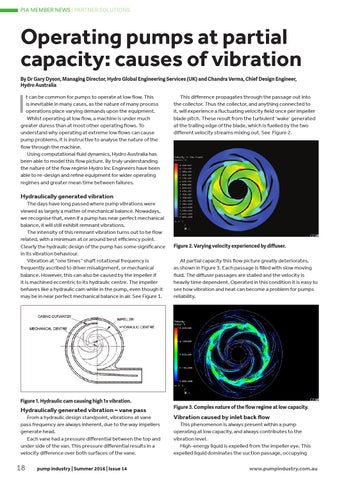
This difference propagates through the passage out into the collector. Thus the collector, and anything connected to it, will experience a fluctuating velocity field once per impeller blade pitch. These result from the turbulent ‘wake’ generated at the trailing edge of the blade, which is fuelled by the two different velocity streams mixing out. See Figure 2.
Hydraulically generated vibration The days have long passed where pump vibrations were viewed as largely a matter of mechanical balance. Nowadays, we recognise that, even if a pump has near perfect mechanical balance, it will still exhibit remnant vibrations. The intensity of this remnant vibration turns out to be flow related, with a minimum at or around best efficiency point. Clearly the hydraulic design of the pump has some significance in its vibration behaviour. Vibration at “one times” shaft rotational frequency is frequently ascribed to driver misalignment, or mechanical balance. However, this can also be caused by the impeller if it is machined eccentric to its hydraulic centre. The impeller behaves like a hydraulic cam while in the pump, even though it may be in near perfect mechanical balance in air. See Figure 1.
Figure 1. Hydraulic cam causing high 1x vibration.
Hydraulically generated vibration – vane pass From a hydraulic design standpoint, vibrations at vane pass frequency are always inherent, due to the way impellers generate head. Each vane had a pressure differential between the top and under side of the van. This pressure differential results in a velocity difference over both surfaces of the vane.
18
pump industry | Summer 2016 | Issue 14
Figure 2. Varying velocity experienced by diffuser.
At partial capacity this flow picture greatly deteriorates, as shown in Figure 3. Each passage is filled with slow moving fluid. The diffuser passages are stalled and the velocity is heavily time dependent. Operated in this condition it is easy to see how vibration and heat can become a problem for pumps reliability.
Figure 3. Complex nature of the flow regime at low capacity.
Vibration caused by inlet back flow This phenomenon is always present within a pump operating at low capacity, and always contributes to the vibration level. High-energy liquid is expelled from the impeller eye. This expelled liquid dominates the suction passage, occupying
www.pumpindustry.com.au