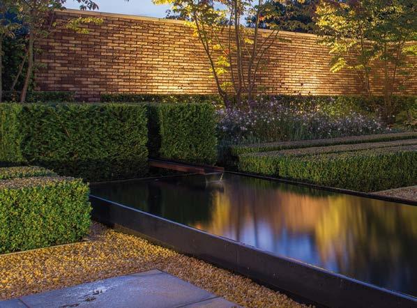
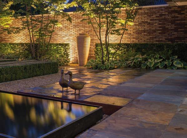
WATER INSTALLATION
Bottom/wall drains for liner ponds
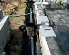
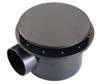
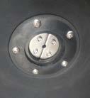
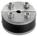
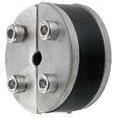
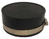
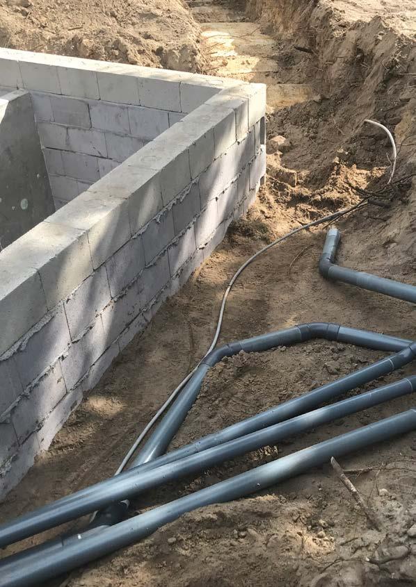
Bottom drains are plastic 'bottom pits' that are connected to a PVC pipe or hose and transport water to a filter/pump system. These ducts promote water circulation.
• Can be glued to PVC pipes.
• Suitable for liner ponds.
• Drain 50 and 110 with height-adjustable dome.
• Stainless-steel screws.

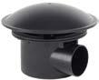
A 110-mm drain connected to a Ø 110 mm PVC pipe allows the passage of a max. capacity of approximately 11 m3/hour, in gravity drainage conditions. A 50-mm drain, connected to a PVC pipe Ø 50 mm, allows the passage of a max. capacity of approximately 5 m3/hour in gravity drainage conditions.
Application
• Use as a bottom drain
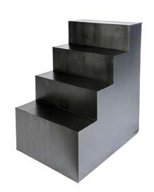
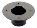
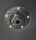
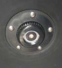
Bottom drains are used to drain water containing bottom contamination, which is blown into a pond and sinks, or is caused by the fish population in the pond, especially koi. The circumference range for draining bottom contamination around the bottom drain is limited; depending on the size and design of the pond, it may be necessary to install several bottom. The 'dome' serves as a convex cover and the height can be adjusted, depending on the fish population. The drain has a grid that can be walked over for use in swimming ponds.
• Use as a wall drain
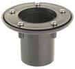
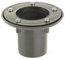
The wall drain 110 with grid is suitable for installing in side walls.
•
•
•


6 6
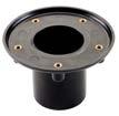
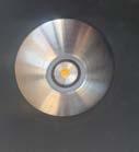
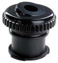
Type Connection ø mm Material Colour Art. no. Bottom drain 50 50 ABS Black 901052 Bottom drain 110 110 ABS Black 901053 Wall drain 110/125 110 / 125 ABS Black 901065 Flush grid for 901065 – PE Black 901066 Insertion grid 110 Incorporated in bottom drain Insertion dome 110 Incorporated in bottom drain Insertion grid and insertion dome for bottom drain 110 The flat insertion fittings have been especially designed for swimming ponds and can be walked on. The insertion dome can remove waste material such as leaves. Type Suitable for Material Colour Art. no. Insertion grid Bottom drain 110 PE Black 901075 Insertion dome Bottom drain 110 PE Black 901076
Easy to remove.
Stainless-steel bolts/nuts for aligning/additional ballast weight.
Can be walked on.
drain 110
Wall drain 125/110 with grid Bottom
with dome
• Can be glued to PVC pipes.
• Suitable for liner, PE and polyester ponds.
• Stainless-steel screws.
• Grommet not included.
• Can be glued to PVC pipes.
• Suitable for liner, PE and polyester ponds.
• Stainless-steel screws.
• Grommet not included.


7 7
Wall ducts, standard, with flat flange
Wall ducts, thick-walled, with flat flange
Type Connection ø mm Material Colour Art. no. Wall duct 40 40 ABS Black 901090 Wall duct 50 50 ABS Black 901091 Wall duct 63 63 ABS Black 901092 Wall duct 90 90 ABS Black 901094 Wall duct 110 110 ABS Black 901095 Type Connection ø mm Material Colour Art. no. Wall duct 40 40 ABS Black 901080 Wall duct 50 50 ABS Black 901081 Wall duct 63 63 ABS Black 901082 Wall duct 75 75 ABS Black 901083 Wall duct 110 110 ABS Black 901085
Wall ducts are used in connection with PVC pipes or hoses, to transport water to and from a filter/pump system.
Thick-walled wall duct
Flat flange connection Standard wall duct
The WD 50 is fitted with a curved flange; the liner is clamped behind the counter flange so the entire duct lies flush to the wall. The wall duct has a bayonet connection on the inside, which can be connected to the adjustable water inlet of the WMD 50 system with a single click/twist.
• Can be glued to PVC pipes.
• Suitable for liner ponds.
• Stainless-steel screws.
• Incl. grommet.
• Suitable for installation with adjustable water inlet 901046.
• Suitable for recessed LED spotlight WDX 8 (with inflow 901046).
• Suitable for recessed LED spotlight WDX
Set includes
• 50-mm wall duct.
• Small 6 - 10 mm cable seal.
• Large 10 - 15 mm cable seal.
• Adjustable water inlet.
Application
• Watertight power cable ducts with cable seal.
• Inflow for return water in the pond with adjustable water inlet.
• Connection of recessed LED wall floodlight WDX 8 and WDX 15.
8 8
50-set
WATER INSTALLATION Wall duct WD 50, thick-walled, with curved flange Wall duct system WDM
50 mm wall
set,
seals and adjustable
inlet for universal application. Type Connection ø mm Material Colour Art. no. Wall duct WD 50 50 ABS Black 901045 Type Connection ø mm Material Colour Art. no. WDM 50 set 50 ABS / Stainless steel / EPDM Black 901044 Wall duct WD 50
All-in
duct
including 2 cable
water
WD 50 passage with many application possibilities
15
(inflow not required).
Cable seal Adjustable water inlet WDX 8 WDX 15
WDM 50 wall duct system in individual components
The WDM 50 set (901044) is also available separately as components.
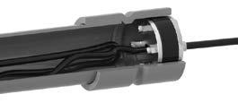
The seal can be used to close off power cables to make them watertight, suitable for installation in a 50-mm wall duct or PVC pipe. An Allen key is used to compress the stainless-steel plates together, which forces the rubber seal outwards and closes the 50 mm pipe, making it watertight.
Pump power cables no longer need to be laid over a pond edge, but can be inserted, including the moulded plug, through the pond wall, completely out of sight.
Built-in wall lighting power cables are also sealed in the same way, the PVC pipe between the seal and wall duct serves to store the lamp cable, so that the lamp can be taken out of the duct.
9 9
Cable seal operation
Type Diameter ø mm Cable ø mm Material Art. no. Cable seal 6 50 6 - 10 Rubber - stainless steel 901047 Cable seal 10 50 10 - 15 Rubber - stainless steel 901048 Adjustable water inlet – – ABS 901046 Wall duct WD 50 – – ABS 901045 Cable seal Adjustable water inlet Wall duct 50
11 11
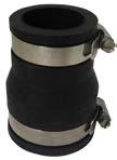
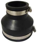
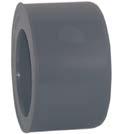
Type Connection mm Art. no. Flexible reduction socket 50 x 40 50 x 40 905020 Flexible reduction socket 63 x 40 63 x 40 905021 Flexible reduction socket 63 x 50 63 x 50 905022 Flexible reduction socket 75 x 63 75 x 63 905026 Flexible reduction socket 110 x 50 110 x 50 905023 Flexible reduction socket 110 x 63 110 x 63 905024 Flexible reduction socket 110 x 90 110 x 90 905025 Reduction socket 110 x 63 Reduction socket 50 x 40
Flexible reduction sockets
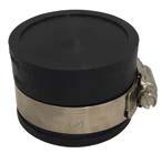
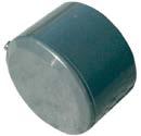
caps Type Connection mm Art. no. Flexible end cap 50 50 905008 Flexible end cap 63 63 905009 Flexible end cap 110 110 905010 End cap 110 End cap 50
Flexible
end
12 12
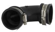
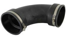
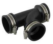
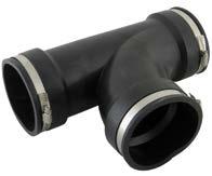
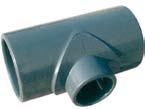
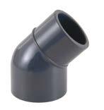
Flexible bends Flexible T-pieces Type Connection mm Art. no. Flexible bend 50 50 905015 Flexible bend 63 63 905016 Flexible bend 110 110 905018 Type Connection mm Art. no. Flexible T-piece 50 50 905030 Flexible T-piece 63 63 905031 Flexible T-piece 110 110 905032
WATER INSTALLATION
Bend 110
T-piece 110
Flexible
Bend 50
50
Flexible T-piece
Application in pressure pipe systems for shutting off pumps, UV-C equipment and filters.
•
•
Application in pressure pipe systems for shutting off pumps, UV-C equipment and filters.
•
•
15 15
valves
union
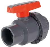
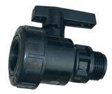
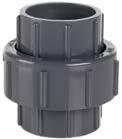
Ball valves PVC-U single union
Ball
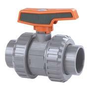
PVC-U double
Removable
handle.
Removable
ball.
Removable
handle.
Removable
ball.
valve with single union Ball valve with double union Type Connection mm Max. pressure Bar Material Art. no. Ball valve 32 32 10 PVC-U 904087 Ball valve 40 40 10 PVC-U 904088 Ball valve 50 50 10 PVC-U 904089 Ball valve 63 63 10 PVC-U 904090 Type Connection mm Max. pressure Bar Material Art. no. Ball valve 25 25 10 PVC-U 904091 Ball valve 32 32 10 PVC-U 904092 Ball valve 40 40 10 PVC-U 904093 Ball valve 50 50 10 PVC-U 904094 Ball valve 63 63 10 PVC-U 904095
Ball
Application in pressure pipe systems for shutting off and diverting the water flow in a system.
• One side shut off.
• Two sides open.
• 2 solvent connections.
• The glass can be removed.
16 16
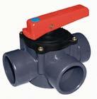
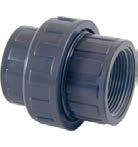
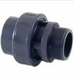
WATER INSTALLATION PVC-U three-way valve Ball valve female/male thread
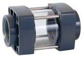
PVC-U sight glass
Compact budget ball valve for general applications.
Three-way valve Ball valve
glass Type Connection mm Max. pressure Bar Material Art. no. Three-way valve 50 50 - 63 6 PVC-U 904118 Type Connection inches Max. pressure Bar Material Art. no. Ball valve 1 1 "male / female 10 PVC-U VA60024 Type Connection mm Max. pressure Bar Material Art. no. 63 sight glass 63 6 PVC-U/glass 904130
Built into a pipe system to control the flow.
Sight
• With PVC solvent unions.
• Minimum flow losses.
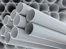
PVC pressure pipe, has many applications, such as in pump and filter systems.
• With smooth ends.
• Grey.
• Suitable as a pressure pipe.
17 17
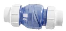
PVC-U Non-return valve Type Connection mm Art. no. Non-return valve 50 2 x 50 904140 Non-return valve 63 2 x 63 904141 Spring-loaded non-return valve 63 2 x 63 904150
PVC-U Non-return valve Built-in non-return valve with solvent unions.
PVC pressure pipe
length
PVC pipe Type Diameter ø mm Length of m Max. pressure Bar Art. no. PVC pipe 32 32 2.2 10 904097 PVC pipe 50 50 2.2 10 904099 PVC pipe 63 63 2.2 10 904100 PVC pipe 75 75 2.2 10 904103 PVC pipe 90 90 2.2 10 904101 PVC pipe 110 110 2.2 10 904102
PVC pressure pipe
sawn to
for easy transport.
Triple union PVC-U solvent unions
For expanding equipment that has been built into the pipe systems.
• 2 solvent connections.
• Coupler with O-ring seal.
Triple union PVC-U solvent/threaded female unions
For expanding equipment that has been built into the pipe systems.
• Solvent/male union.
• Coupler with O-ring seal.
Triple union PVC-U solvent/threaded male unions
For expanding equipment that has been built into the pipe systems.
• Solvent/male union.
• Coupler with O-ring seal.
18 18 WATER INSTALLATION Solvent union Solvent/threaded union Solvent/threaded union
Type Connection mm Max. pressure Bar Material Art. no. 25 solvent union 25 10 PVC-U 904078 32 solvent union 32 10 PVC-U 904079 40 solvent union 40 10 PVC-U 904080 50 solvent union 50 10 PVC-U 904081 63 solvent union 63 10 PVC-U 904082 75 solvent union 75 10 PVC-U 904083 90 solvent union 90 10 PVC-U 904084 110 solvent union 110 10 PVC-U 904085
Type Connection mm Max. pressure Bar Material Art. no. 32 solvent/threaded union 1" x 32 10 PVC-U 904108 40 solvent/threaded union 5/4" x 40 10 PVC-U 904109 50 solvent/threaded union 1½" x 50 10 PVC-U 904110 63 solvent/threaded union 2" x 63 10 PVC-U 904111 90 solvent/threaded union 3" x 90 10 PVC-U 904107
Type Connection mm Max. pressure Bar Material Art. no. 50 solvent/threaded union 1½” x 50 10 PVC-U 904133 63 solvent/threaded union 2” x 63 10 PVC-U 904134
•
19 19
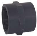
PVC-U socket solvent x female union
Solvent
Type Connection mm Max. pressure Bar Material Art. no. 25 socket/female 25 x ¾” 10 PVC-U 904059 32 socket/female 32 x 1" 10 PVC-U 904060 40 socket/female 40 x 1¼" 10 PVC-U 904061 50 socket/female 50 x 1½" 10 PVC-U 904062 63 socket/female 63 x 2" 10 PVC-U 904063
x female union.
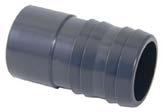
Solvent/hose fitting
Solvent fitting Type Connection mm Max. pressure Bar Material Art. no. 25 solvent fitting 25 x 25 10 PVC-U 904114 32 solvent fitting 32 x 32 10 PVC-U 904115 40 solvent fitting 40 x 40 10 PVC-U 904116 50 solvent fitting 50 x 50 10 PVC-U 904117
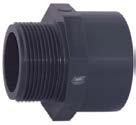
x PVC-U male connectors
• Solvent/hose connection. Connecting the PVC fittings to the hose.
Solvent
Connector Type Connection mm Max. pressure Bar Material Art. no. 25 connector/male 25 x ¾” 10 PVC-U 904053 32 connector/male 32 x 1" 10 PVC-U 904054 40 connector/male 40 x 1¼" 10 PVC-U 904055 50 connector/male 50 x 1½" 10 PVC-U 904056 63 connector/male 63 x 2" 10 PVC-U 904057 90 connector/male 90 10 PVC-U 904058
• Solvent x male union.
Socket
20 20
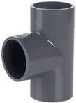
T-piece 90º PVC-U T-pieces
3 solvent connections. Type Connection mm Max. pressure Bar Material Art. no. T-piece 25 25 10 PVC-U 904001 T-piece 32 32 10 PVC-U 904002 T-piece 40 40 10 PVC-U 904003 T-piece 50 50 10 PVC-U 904004 T-piece 63 63 10 PVC-U 904005 T-piece 75 75 10 PVC-U 904006 T-piece 90 90 10 PVC-U 904007 T-piece 110 110 10 PVC-U 904008 90º PVC-U T-piece reduction bends • 3 solvent connections. T-piece reduction bend Type Connection mm Max. pressure Bar Material Art. no. T-piece reduction bend 32 x 25 10 PVC-U 904009 T-piece reduction bend 40 x 25 10 PVC-U 904101 T-piece reduction bend 40 x 32 10 PVC-U 904011 T-piece reduction bend 50 x 32 10 PVC-U 904012 T-piece reduction bend 50 x 40 10 PVC-U 904013 T-piece reduction bend 63 x 40 10 PVC-U 904014 T-piece reduction bend 63 x 50 10 PVC-U 904015 T-piece reduction bend 90 x 63 10 PVC-U 904016 T-piece reduction bend 110 x 90 10 PVC-U 904017
WATER INSTALLATION
•
90º bend
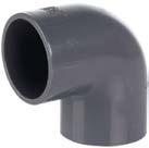
90º PVC-U bends
Type Connection mm Max. pressure Bar Material Art. no. 90º bend 25 25 10 PVC-U 904037 90º bend 32 32 10 PVC-U 904038 90º bend 40 40 10 PVC-U 904039 90º bend 50 50 10 PVC-U 904040 90º bend 63 63 10 PVC-U 904041 90º bend 75 75 10 PVC-U 904042 90º bend 90 90 10 PVC-U 904043 90º bend 110 110 10 PVC-U 904044
• 2 solvent connections.
•
•
•
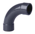
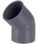
21 21 45º PVC-U bends 90° PVC-U long-bend T-pieces 45° PVC-U bend 45º bend 90º long bend 45º bend
2
solvent connections.
2
solvent connections.
3
Type Connection mm Max. pressure Bar Material Art. no. 45º bend 25 25 10 PVC-U 904045 45º bend 32 32 10 PVC-U 904046 45º bend 40 40 10 PVC-U 904047 45º bend 50 50 10 PVC-U 904048 45º bend 63 63 10 PVC-U 904049 45º bend 75 75 10 PVC-U 904050 45º bend 90 90 10 PVC-U 904051 45º bend 110 110 10 PVC-U 904052 Type Connection mm Max. pressure Bar Material Art. no. Bend 50 50 10 PVC-U 904147 Bend 63 63 10 PVC-U 904148 Bend 75 75 10 PVC-U 904149 Bend 110 110 10 PVC-U 904153 Type Connection mm Max. pressure Bar Material Art. no. Bend 63 x 63 x 50 10 PVC-U 904127
solvent connections.
•
23 23
Reduction
PVC-U reduction rings
ring
Type Connection mm Max. pressure Bar Material Art. no. Reduction ring 32 x 25 10 PVC-U 904072 Reduction ring 40 x 32 10 PVC-U 904073 Reduction ring 50 x 20 10 PVC-U 904138 Reduction ring 50 x 40 10 PVC-U 904074 Reduction ring 63 x 50 10 PVC-U 904075 Reduction ring 75 x 63 10 PVC-U 904124 Reduction ring 90 x 63 10 PVC-U 904076 Reduction ring 110 x 63 10 PVC-U 904077
• 2 solvent connections.
End cap
Solvent PVC-U end caps
Solvent
Type Connection mm Max. pressure Bar Material Art. no. End cap 25 25 10 PVC-U 904064 End cap 32 32 10 PVC-U 904065 End cap 40 40 10 PVC-U 904066 End cap 50 50 10 PVC-U 904067 End cap 63 63 10 PVC-U 904068 End cap 75 75 10 PVC-U 904069 End cap 90 90 10 PVC-U 904070 End cap 110 110 10 PVC-U 904071
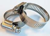
worm
clamps
gear clamps, suitable for sealing hoses. Worm gear clamps Type Hose size mm Material Art. no. Worm gear hose clamp 8 - 12 Stainless steel 304 VA 34440 Worm gear hose clamp 10 - 16 Stainless steel 304 VA 34441 Worm gear hose clamp 12 - 20 Stainless steel 304 VA 34442 Worm gear hose clamp 20 - 32 Stainless steel 304 VA 34444 Worm gear hose clamp 25 - 40 Stainless steel 304 VA 34445 Worm gear hose clamp 32 - 50 Stainless steel 304 VA 34446 Worm gear hose clamp 40 - 60 Stainless steel 304 VA 34447
Stainless-steel 304 model.
Suitable for smooth hoses.
union.
Stainless-steel
gear
Worm
•
•
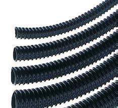
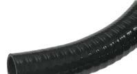
Pond hoses, standard quality
• Reinforced with spiral.
• Not suitable for burying.
• Very flexible.
• Smooth inner wall.
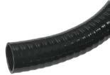
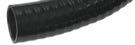
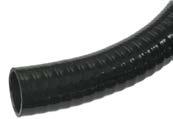
• Thick-walled.
Pond hoses, thick-walled
• Reinforced with spiral.
• Suitable for underground installation.
• Very flexible.
• Smooth internal and external wall.
24 24
WATER INSTALLATION
Very elastic spiral hose for connecting pond pumps, filters, ornaments, etc.
Standard
Type Hose diameter mm Roll m Max. pressure Bar Colour Art. no. Hose 13 13 30 1 Black 611001 Hose 20 20 30 1 Black 611003 Hose 25 25 30 1 Black 611004 Hose 32 32 25 1 Black 611005 Hose 40 40 20 1 Black 611006 Hose 50 50 20 1 Black 611007 Type Hose diameter mm Roll m Max. pressure Bar Colour Art. no. Hose 20 20 25 5 Black 612001 Hose 25 25 25 5 Black 612002 Hose 32 32 25 5 Black 612003 Hose 40 40 25 5 Black 612004 Hose 50 50 25 5 Black 612005
Very elastic spiral hose for connecting pond pumps, filters, ornaments, etc. where the hose is suitable for burying.
pond hose
Thick-walled pond hose
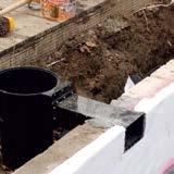
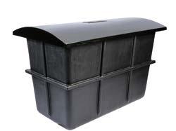
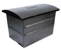
Polyester pits with cover
Equipment pits for integrated pumps, filters and UV-C equipment, including cover. The pits are reinforced, however, building regulations must be observed to prevent the pit from being raised or depressed due to high groundwater. The pits have a curved lid so rainwater does not collect on top and can flow inside.
• Fibreglass-reinforced polyester, black.
• Including cover.
• Reinforced walls.
• Take structural facilities into account.
25 25
Equipment pit 800 Equipment pit 1200 Equipment pit 1500 Equipment pit installation method Type Outer diameter L x W x H cm Bottom dimensions L x W cm Material Art. no. Equipment pit 800 81 x 62.5 x 76 57 x 38 Polyester 201017 Equipment pit 1200 119 x 79 x 80 104 x 64 Polyester 201020 Equipment pit 1500 165 x 91 x 100 130 x 59 Polyester 201021 Concrete base Ground level Cover Stabilised sand Groundwater level dependent Pit Anchoring pit to concrete base
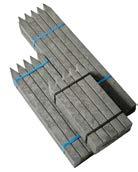
VarioPic posts for installation of VarioLat and VarioPlank
Solid posts for the installation of VarioLat and Varioplank, length depends on the soil type and application. Recommended distance between posts is 50 cm.
• Solid posts, easy to use screws.
• Made of recycled plastic.
28 28
WATER INSTALLATION
VarioPic 40 - 60 - 80 Type Dimensions cm Colour Bundle pcs Art. no. VarioPic 40 4 x 4 x 40 Grey 10 602003 VarioPic 60 4 x 4 x 60 Grey 10 602004 VarioPic 80 4 x 4 x 80 Grey 10 602005
WATER INSTALLATION
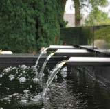
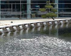
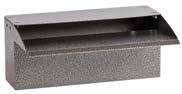
Aluminium-coated waterfalls
With reservoir for stabilising the water flow.
• Coated aluminium.
• Uniform water film.
• Openings for anchoring.
• Incl. hose connection.
When deciding what pump to choose, in addition to the capacity, it is important to take the pressure – including hose/pipe resistance – into account.
30 30
Waterfall 30 Waterfall 90 Waterfall table Type Dimensions mm Run mm Connecting hose mm Material Colour Art. no. Waterfall 30 304 x 195 x 134 107 3/4" x 25 Aluminium Grey 409030 Waterfall 60 604 x 195 x 134 107 11/4" x 40 Aluminium Grey 409031 Waterfall 90 904 x 195 x 134 107 2" x 50 Aluminium Grey 409032 Height mm Capacity in l/h 30 60 90 250 2200 4300 6500 500 3250 6500 9700 750 4300 8650 13000 1000 5400 10800 16200 1250 6500 13000 19500 1500 7500 15000 22500
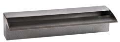
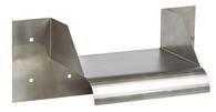
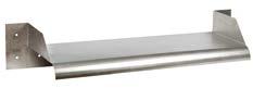
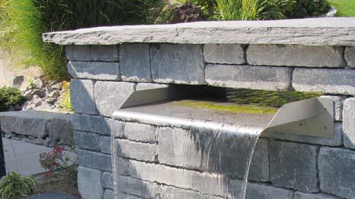
Stainless-steel waterfall elements
• Blasted stainless steel.
• Uniform water film.
• Easy installation. Overflow waterfall suitable for wall installation.
31 31
Waterfall element 30 Waterfall element 90 Waterfall element 60 cm Type Water course dimensions mm Total dimensions mm Material Art. no. Waterfall element 30 300 x 250 x 80 460 x 250 x 160 Blasted stainless steel 409040 Waterfall element 60 600 x 250 x 80 760 x 250 x 160 Blasted stainless steel 409041 Waterfall element 90 900 x 300 x 80 1060 x 300 x 160 Blasted stainless steel 409042
Calculation of the pipe or friction losses.
When water flows through a pipe system pressure losses occur as a result of friction in the pipe system. To keep these losses at a minimum, the correct pipe diameter must be determined with regard to the capacity that will flow through the pipe. If the pipe diameter used is too small, this will lead to increased friction and the pump capacity will reduce considerably due to the resistance. When selecting the correct diameter, the most efficient pump can be selected with the lowest possible power consumption.
To easily calculate the losses, use the pressure loss table below as a tool. The loss is expressed in terms of pressure (H in m) per 100 metres of PVC pipe.
To be able to calculate the total friction in a pipe system, the friction of the bends, T-pieces and valves must also be calculated. The following conversion table shows the friction in metres of straight pipe.
32 32 WATER INSTALLATION
Pressure loss (H in m) per 100 metres of pipe Friction (m) ø of the pipe mm Max. m3/h capacity 5 10 15 20 30 40 32 17 50 80 – – –40 4.5 13 26 40 – –50 1.3 5 9 14 30 50 63 0.5 1.7 4.2 6 15 17 75 0 0.7 1.5 2.5 4.5 8.5 90 0 0 0.7 1.3 2 3.5 110 0 0 0.4 0.7 1.3 2.5 125 0 0 0.1 0.2 0.4 0.8 ø of the pipe mm Bend T-piece Valve 90º 45º 90º Ball Slide 32 0.7 0.4 1.8 0.9 0.20 40 0.8 0.5 2.3 11.0 0.25 50 1.0 0.6 2.9 15.0 0.30 63 1.4 0.7 3.5 17.0 0.40 75 1.7 0.8 4.0 20.0 0.45 90 1.9 1.1 5.0 25.0 0.55 110 2.1 1.3 6.0 29.0 0.60 125 2.6 1.6 7.0 35.0 0.80
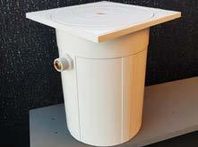
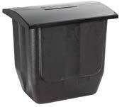
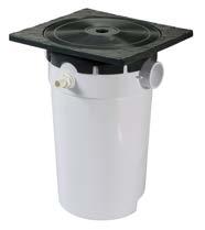
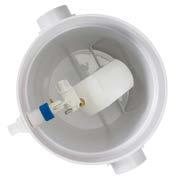
EASY-FILL Pro Water constant level system
Easy-to-install water suppletion system. Built-in float regulates automatic suppletion of tap water to maintain the level in the (swimming) pond.
Connection to the water basin with a 50 mm pipe fitted to a wall duct.
Two connectors of your choice are available for this purpose: on the bottom and on the side of the housing.
• Visible parts made of black plastic.
• Cover and housing made of UV-resistant ABS.
• Water level measurement with a float.
• Additional overflow connection.
• Removable inspection hatch.
33 33
Type Connections mm/inch Dimensions mm Art. no. Basin Overflow Water suppletion EASY-FILL Pro 50 mm 50 mm ½" 266 x 246 x 338 901903 EASY-FILL Pro EASY-FILL Pro top view 57 / 77 6 43 Ø50 331 , 1 / 338 1 8 Ø 50 246 26 6