
10 minute read
Global Sulphur Cap 2020 (Part 2

from Wavelength #69
Technical
Global Sulphur Cap 2020 (Part 2)
Advertisement
The global 0.50% sulphur cap will be introduced in 2020, and up to 70,000 ships may be affected by the regulation according to IMO estimates. There are the following options to ensure compliance with the Global Sulphur Cap: 1. Low sulphur distillate fuels 2. Low sulphur heavy fuel oil 3. Scrubber installation and operation on HSFO 4. LNG as fuel 5. Use of alternative fuels and technologies The first two options were described in the previous Wavelength issue (no. 68).
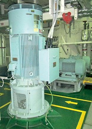
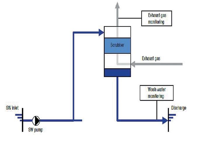
- Introduction HSFO will still be an option after 2020. However, to be in compliance, it will require the installation of exhaust gas cleaning technology commonly known as SOx scrubbers. No changes will have to be made to the engines or fuel treatment plant, but the installation of a scrubber could be complex, especially for retrofits. There is a significant investment cost for the exhaust gas cleaning plant and there will also be operational expenses related to increased power consumption and the possible need for chemical consumables and sludge handling. In the scrubber, the exhaust gas is cleaned by water on its way to the funnel. The water is injected into the exhaust gas stream and is discharged from the bottom of the scrubber. The water used in the cleaning process could be either sea water (SW) or fresh water (FW). - Types of Scrubbers • Open loop type • Closed loop type • Hybrid (Open / Closed loop) - Open Loop Type • In this open loop design exhaust gas enters the scrubber and is sprayed with seawater. The SOx in the exhaust then reacts with water to form sulphuric acid. • Chemicals are not required since the natural alkalinity of seawater neutralizes the acid and the water is discharged into the sea without any further treatment. • Open loop scrubbers can meet both 0.50 and 0.10% sulphur requirements and can be used in all areas with significant sea water alkalinity, except where there are restrictions on wash water discharge. Figure 1: Open loop Scrubber
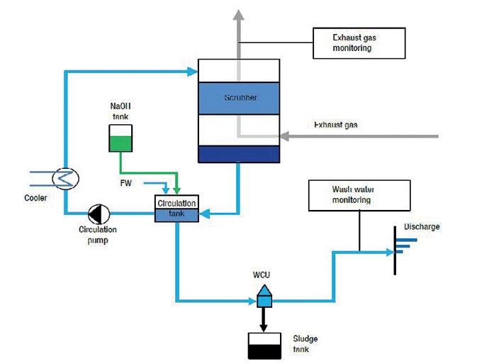
- Closed Loop Type • In a closed loop scrubber fresh water (FW) is used for cleaning. The wash water is mixed with caustic soda (NaOH) to boost the alkalinity of the wash water, which is then recirculated through the system and partially purged. • Bleed-off water has to undergo a cleaning process, which is performed in a water cleaning unit (WCU). The sludge is then led to a sludge tank. • The closed loop system offers a high degree of flexibility for the vessel as the use is not restricted by local regulations. • The initial costs are higher than those of the open loop system due to the additional equipment required. In addition, operating costs are higher mainly because of the constant addition of chemicals.
- Hybrid Scrubber (Open / Closed loop) • The hybrid scrubber combines both an open and a closed loop system and each of their operation modes. Due to the combination, the hybrid system is more complex, but it offers the highest degree of flexibility. • The open loop mode is typically used in open waters where the alkalinity is sufficiently high for effective scrubbing. • The closed loop system is used in certain enclosed waters, harbours or where the alkalinity of sea water is low. • The initial cost of the hybrid scrubber is higher. However, it offers the lowest operating costs as it can switch to the most economic mode in any situation.


Figure 3: Hybrid Scrubber
- U-Design and I-Design (in-line) Scrubbers Both U-design and I-design (in line) scrubbers can be configured with multiple inlets. This reduces space requirements and installation costs by allowing one scrubber to handle exhaust gas from multiple sources, including boilers and both the main/auxiliary engines.
Figure 4: U-Design (left) and I-Design (right) Scrubbers Figure 5: U-Design Scrubber installation example
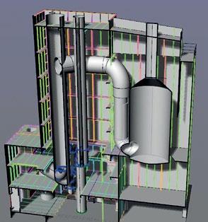

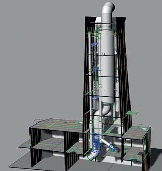
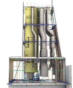
Figure 6: I-Design Scrubber installation example
- Advantages & Disadvantages of Scrubbers
Advantages Disadvantages Can use conventional HSFO High initial investment Possible for retrofit 2-3% fuel penalty Reduces particulate matter Requires space for scrubber as well as SOx emissions tower and supporting systems Requires chemicals (closed loop) Requires integration with ship’s power management system Requires monitoring
4. Use of LNG as fuel
LNG as fuel is now a technically proven solution, and the LNG bunkering infrastructure is developing rapidly. The complete removal of SOx and PM emissions and a reduction in NOx emissions of up to 85% through the use of LNG is a strong argument for the use of LNG, especially in the ECAs. In addition, LNG can also to some extent reduce CO2 emissions by up to 25%. It also has a positive impact on the Energy Efficiency Design Index (EEDI) of the ship. However, due to the following reasons the use of LNG as fuel can only be considered for specific cases of newbuildings: • There is a high investment cost. -The most expensive item in the LNG package are the LNG tanks.
Technical
-The second most costly item is the “Fuel Gas Supply”
System (FGS). • Space is required for the tank. • The LNG Tank Capacity depends on the cruising range and engine consumption. - For the same energy content the LNG capacity is approximately 1.6 x volume of HFO. • There has to be a methane slip in the exhaust. • There are large regional variations in the price of LNG. • There is a lack of LNG bunkering infrastructure. • Some engine types need additional systems to reach Tier III.
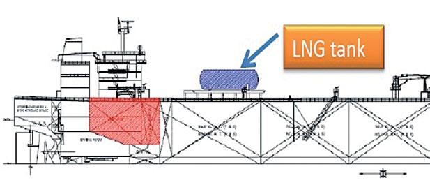
Figure 7: Space for LNG tank
- Dual-fuel two-stroke engines (DF Engines) Owners currently have the choice of two different engine solutions for two-stroke, low speed propulsion for LNG vessels: MEGI, by MAN Diesel and Turbo, and X-DF, by WinGD (previously Wärtsilä). The MAN Diesel & Turbo engines compress the air, start the combustion process by injecting fuel oil and injecting the gas into the burning air/oil fuel mixture. This also enables the operation, according to the Diesel-Cycle, in gas mode as well, and is the reason why the gas pressure must be high (300 bar for natural gas).
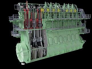
Figure 8: MAN Diesel and Turbo engine / ME-GI engine Figure 9: WinGD / W-XDF type
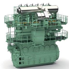
The WinGD engines inject the gas at the beginning of the compression after the air has entered the cylinder. During the low pressure phase at the beginning of compression, only a low gas pressure is required i.e.16bar. The gas/air mixture is ignited at the end of the compression stroke by the pilot oil. Thus, the engine works in the same way as an Otto-Cycle engine. Figure 10: Fuel Gas Supply System (FGS) for high pressure slow speed DF engine (300 bars)
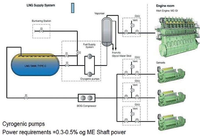

Figure 11: Fuel Gas Supply System (FGS) for low pressure slow speed DF engine (16 bars)
-Advantages and Disadvantages of LNG as fuel
Advantages Disadvantages
Has good environmental performance Can reach NOx Tier III performance High investment cost
Costly to retrofit
Has a positive impact on EEDI Large regional variations in LNG price Methane slip in exhaust Requires space for tank Some engine types need additional systems to reach NOx Tier III
5. Use of Alternative Fuels and Technologies Alternatives to the above fuels include liquefied petroleum gas (LPG), ethane, methanol, compressed natural gas (CNG), bio-fuel, solar/ wind power, fuel cells and batteries. Currently, none of these fuels and technologies is widely used in the marine industry. However, it is expected that some of these emerging technologies may become more common in the future. - Other liquid or gaseous fuel options (Liquefied Petroleum Gas (LPG), Methanol and Ethanol, Di-Methyl Ether (DME) etc.): A number of liquid fuels can be used in dual fuel engines as a substitute for oil. Typically, a small quantity of marine fuel oil is used as pilot fuel to initiate the ignition process. This is followed by combustion of the selected alternative fuel. Most of these fuels offer significant reductions in NOx and Particulate Matter emissions. They are also sulphur free and can be used for compliance with the ECA regulations. Due to the limited availability of all these fuels, it is not expected that they will penetrate deep sea shipping sectors in the near to medium term future.
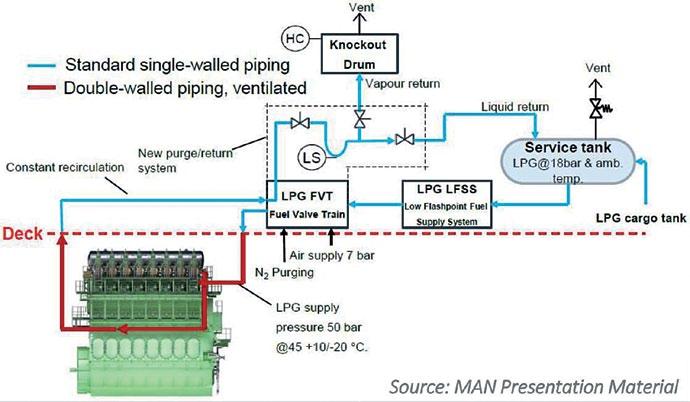
Figure 12: LPG Fuel Supply System
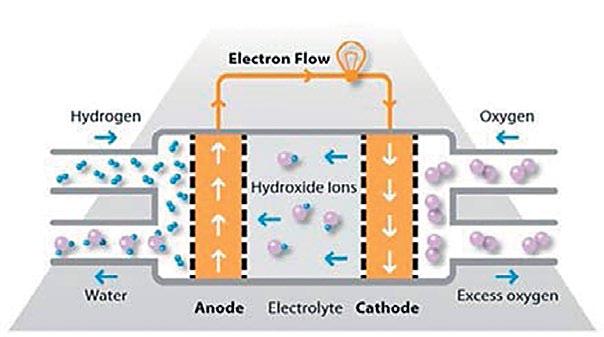
- Biofuels: These can be derived from edible crops, non-edible crops (waste, or crops harvested on marginal land) and algae, which can grow on water and do not compete with food production. Biofuels derived from plants or organisms also biodegrade rapidly, thereby posing far less of a risk to the marine environment in the event of a spill. However, securing the necessary production volume is a challenge. As a result, biofuels will have only limited penetration in the marine fuels market in the next decade. - Solar / Wind Power: While renewable energy (solar, wind) may have some potential to mitigate carbon emissions, it is not seen as a viable alternative for commercial shipping. Certainly, vessels equipped with sails, wind kites or solar panels may be able to supplement existing power generating systems, but the relative unreliability of these energy sources make them illsuited for deep sea transport or operations in some latitudes with seasonal weather conditions. - Hydrogen: Renewable electricity can be employed to produce hydrogen, which can be utilized to power fuel cells on board ships. Hydrogen is the smallest and lightest of all gas molecules, thus offering the best energy-to-weight storage ratio of all fuels. However, hydrogen as fuel can be difficult and costly to produce, transport and store. It also requires six to seven times more space than HFO and cryogenic storage at very low temperatures (-253oC or 20K). - Fuel Cells: Fuel cells offer high electrical efficiencies of up to 60 per cent as well as lower noise and vibration emissions than conventional engines. The main components of a fuel cell power system are the fuel cells, which convert the chemical energy stored in the fuel directly into electrical and thermal energy by electrochemical oxidation. The fuel cell works in a combustion-free electrochemical process. It is only a reforming process that might involve a small amount of fuel combustion. Consequently, cell technology can dramatically reduce emissions into the atmosphere.
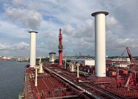
Figure 13: 30-metre- tall Rotor Sails installed on Maersk Pelican Figure 14: Functional principle of a fuel cell
- Batteries: Batteries and hybrid power plants represent a transformation in the way energy is used and distributed on board vessels. Fully electric ships represent a leap forward in power system design, but at present they are only feasible in limited applications such as ferries and short-sea shipping.
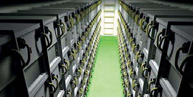
Figure 15: Battery stack
