SPECIAL REPORT: LOAD BED SYSTEMS FOR MODERN MILITARY VEHICLES
A typical zero torsion design always includes a fixed mounting to the chassis at a certain point. This retains the platform and the load, stops the load from moving and tilting and retains side to side and fore and aft loads.
Loadbeds and cargo bodies can be built and subsequently configured to match and optimise the chassis dimensions and characteristics across a fleet of vehicles. They offer the user a high level of flexibility and stretch potential allowing the uUser to carry any existing and foreseeable equipment, stores or personel. Low or Zero Torsion Load Carrying Systems There are two mounting and operating systems available for integrating loadbeds with the chassis known as low torsion mounting and zero torsion (or torsion free) mounting. Selection of either variant should be considered with regard to the performance required from the chassis, transport requirements, constraints placed upon the equipment and the loads to be carried. In each case, the condition that is considered most critical is that of the twisting that is imparted into the vehicle chassis when it is driven over uneven undulating ground. In considering a typical worst case, it may be feasible for 300mm+ of wheel elevation to occur at each axle, with these being diagonally opposite from front to back. In such circumstances substantial twist can occur in the chassis rails. A proportion of the stress resulting from this torsion is then transferred to the load platform that is mounted upon the chassis. Low Torsion The low torsion loadbed design features bearers that run across the loadbed and support the load being mounted above whilst connected by carefully designed and stressed connecting webs to a pair of longitudinal runners. In turn, these runners sit upon and are firmly attached to the chassis rails.
In the case of MVE low torsion loadbeds, springs are fitted as part of the front mounting brackets permitting a degree of compliance under maximum chassis twist to reduce the movement and induced stress. In this configuration the loadbed supports the chassis and will reduce the level of twist imparted to it. In many cases and certainly if vehicles and ISO Containers are carrying loose loads, the impact upon the load being carried is negligible, and if the loadbed and chassis are optimized, the effect will be within design and operational limits. Zero Torsion A typical zero torsion design always includes a fixed mounting to the chassis at a certain point. This retains the platform and the load, stops the load from moving and tilting and retains side to side and fore and aft loads. A pivot is integrated at the front and/or at the rear, positioned to transmit key loads as directly as possible to the subframe/chassis whilst permitting the subframe and chassis to twist, bend and deflect freely. This approach typically: 1) Reduces the torsional loadings into the payload – which is important when carrying delicate equipment. However, it should be recognised that it is not possible to isolate completely torsional loading from an ISO mounted container as it twists at the middle outwards when subjected to centripetal forces such as those encountered when cornering at speed. 2) Allows the chassis greater flexibility, but by the same token does not support the chassis to the same extent as the low torsion system. A zero torsion system typically allows greater axle deflection in severe off-road conditions,
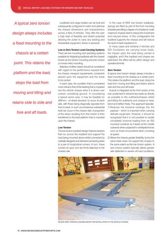
AN MVE ZERO TORSION LOAD BED READY FOR INSTALLATION TO THE VEHICLE CHASSIS.
6 | WWW.DEFENCEINDUSTRYREPORTS.COM