1 minute read
Blower Housing, Cylinder Head, and Breather/Valve Assembly

from John Deere TRS26 Walk-Behind Snowthrowers & Snowblowers Service Repair Manual Instant Download (TM14
by kmd9iso9dkk

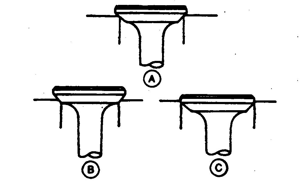
2. On seats with more than 0.0313 in. (0.795 mm) seating surface, cut back seating surface with a 31˚ cutter (A).
3. The valve seat angle (B) depends on valve face angle (C). New valves have a 45˚ face. Recondition valve seats with 56˚ cutter (A), to 0.0469 in. (1.19 mm).
Advertisement
4. Lap valves to seats after refacing.
5. Match valve to seat. Be sure valve seat is centered on valve face. The position of valve in seat is evident after lapping valve.
A—Right B—Wrong C—Wrong
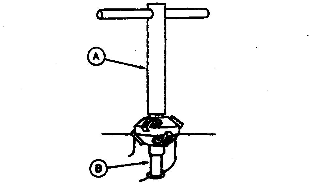
Lap Valves
Lap valve and seat if they do not make good contact.
1. Apply a small amount of lapping compound to valve face.
2. Turn valve in seat using vacuum cup tool.
3. Check valve every eight strokes until a uniform ring appears around surface of valve face.
4. Wash parts in solvent to remove lapping compound.
5. Check position of lap mark on face. Lap mark must be on or near center of valve face.
6. Check valve-to-tappet clearance. (See Section 220, Group 15.)
Other Material
Number
Group 20
Governor, Camshaft, and Tappets
Name
Use
T43512 Thread Lock and Sealer (Medium Apply to governor shaft. Strength)
PT569 John Deere NEVER-SEEZ® Apply to crankshaft end. Lubricant
Suggest:
If the above button click is invalid.
Please download this document first, and then click the above link to download the complete manual.
Thank you so much for reading