3 minute read
Installation Procedure

from Caterpillar Cat 420F BACKHOE LOADER (Prefix SKR) Service Repair Manual Instant Download
by kmd9iso9dkk

Advertisement
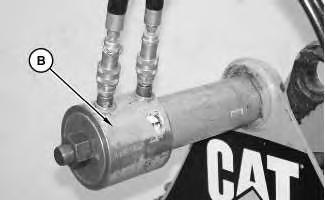
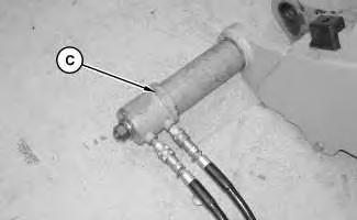
Illustration 14 g02888136
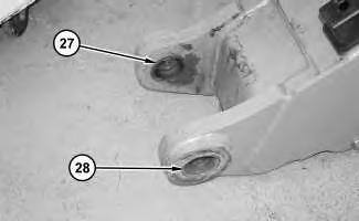
1. Lower the temperature of bearings (28) and (27). Use Tooling (C) in order to install bearings (27) and (28).
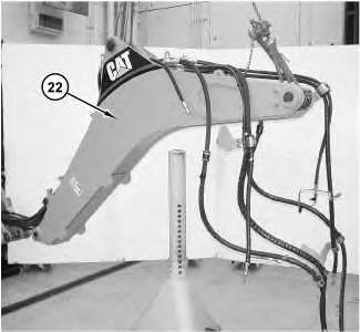
Illustration 15 g02888124
2. Lower the temperature of bearings (25) and (26). Use Tooling (B) in order to install bearings (25) and (26).
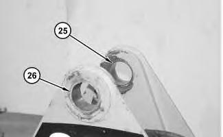
Illustration 16
Illustration 17
3. Attach Tooling (A) and a suitable lifting device to boom (22). The weight of boom (22) is approximately 455 kg (1000 lb). Install boom (22).
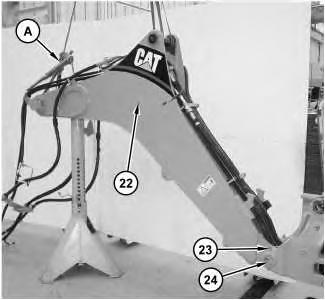
4. Install pin (24) and bolt (23). Repeat for the other side.
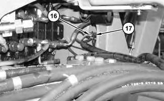
Illustration 18 g02887578
5. Connect harness assembly (16). Install cable strap (17).
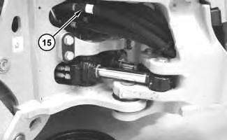
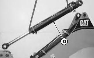
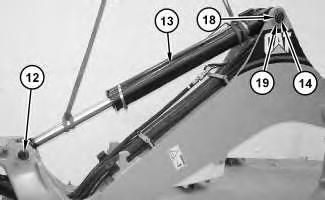
8. Attach a suitable lifting device to boom cylinder (13). The weight of boom cylinder (13) is approximately 115 kg (255 lb). Install boom cylinder (13). Install pin (12). Install pin (14) into one side of boom cylinder (13).
Note: Pin (14) will be fully installed when the stick cylinder is installed.
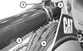
11. Connect hose assemblies (3) and (4). Connect clamp (2). Connect harness assembly (1).
End By: a. Install the stick cylinder. b. Install the stick.
Copyright 1993 - 2019 Caterpillar Inc.
All Rights Reserved.
Private Network For SIS Licensees.
Sun Sep 15 22:06:26 UTC+0800 2019
Previous Screen
Product: BACKHOE LOADER
Model: 420F BACKHOE LOADER SKR
Configuration: 420F Backhoe Loader SKR00001-UP (MACHINE) POWERED BY C4.4 Engine
Disassembly and Assembly
416F, 420F and 430F Backhoe Loaders Machine Systems
Swing Cylinder - Remove and Install
SMCS - 5105-010
Removal Procedure
Cylinders equipped with lock valves can remain pressurized for very long periods of time, even with the hoses removed.
Failure to relieve pressure before removing a lock valve or disassembling a cylinder can result in personal injury or death.
Ensure all pressure is relieved before removing a lock valve or disassembling a cylinder.
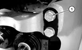
1. Loosen bolts (1) on right side of the bracket.
2. Position the backhoe to the side, as shown.

3. Release the pressure in the hydraulic oil system.

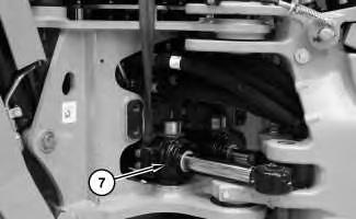
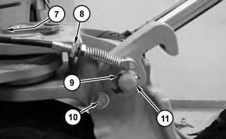
7. Attach a suitable lifting device to swing cylinder (7) . The weight of swing cylinder (7) is approximately 38 kg (85 lb). Remove swing cylinder (7) . Remove any shims that may be present. Repeat for the other side.
Disassembly and Assembly Information
Table 1
Cylinders equipped with lock valves can remain pressurized for very long periods of time, even with the hoses removed.
Failure to relieve pressure before removing a lock valve or disassembling a cylinder can result in personal injury or death.
Ensure all pressure is relieved before removing a lock valve or disassembling a cylinder.
When you are using hydraulic cylinders and puller studs, always ensure that the rated capacity of the puller stud meets or exceeds the rated capacity of the hydraulic cylinder. If the puller stud does not meet or exceed the rated capacity of the hydraulic cylinder, a sudden failure of the puller stud could occur. The sudden failure of the puller stud could result in personal injury or death.
Tooling (A) is used for the removal of bearing (2) .
(4) Before installation, apply Tooling (D) to the threads. Use Tooling (C) to tighten piston (4) . Tighten piston (4) to a torque of 1375 ± 25 N·m (1014 ± 18 lb ft). Tighten setscrew (1) to a torque of 23 ± 3 N·m (204 ± 27 lb in)
(5) Before assembly, apply Tooling (D) to the wiper seal groove. Apply Tooling (B) to the flange.
(6) Before assembly, lubricate the sealing lip with the fluid that is being sealed.
(3) Before assembly, lubricate the threads with Tooling (D) . Use Tooling (C) and Tooling (E) to tighten head (3) . Tighten head (3) to a torque of 775 ± 25 N·m (572 ± 18 lb ft).
Installation Procedure
Note: There should be no grease applied to the cylinder body to frame joint. The joint is a nonlubricated joint that has impregnated bearings installed.
1. Attach a suitable lifting device to swing cylinder (7) . The weight of swing cylinder (7) is approximately 38 kg (85 lb). Install swing cylinder (7) and any shims that were present during the removal procedure.
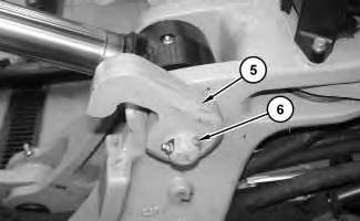
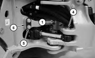
2. Install bracket (6) , bolts (5) , and bolts (1) . Tighten bolts (5) and bolts (1) to a torque of 800 ± 100 N·m (590 ± 74 lb ft). Install pin (4) and the retaining ring.
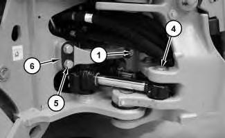
Illustration 10 g02849822
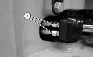
3. Connect hose assemblies (3) . Repeat for the other swing cylinder.
Illustration 11
4. Connect hose assemblies (2) from the head end of the swing cylinder. Repeat for the other swing cylinder.
Suggest:
If the above button click is invalid.
Please download this document first, and then click the above link to download the complete manual.
Thank you so much for reading