
1 minute read
Service

from Caterpillar Cat 420F BACKHOE LOADER (Prefix SKR) Service Repair Manual Instant Download
by kmd9iso9dkk

Shutdown SIS
Previous Screen
Advertisement
Product: BACKHOE LOADER
Model: 420F BACKHOE LOADER SKR
Configuration: 420F Backhoe Loader SKR00001-UP (MACHINE) POWERED BY C4.4 Engine
Disassembly and Assembly
416F, 420F and 430F Backhoe Loaders Machine Systems
Boom - Remove and Install
SMCS - 6501-010
Removal Procedure Table 1
Required Tools
350-7768
350-7769
Electric Hydraulic Pump Gp (115V) 1
Electric Hydraulic Pump Gp (230V0 1
Start By: a. Remove the stick. b. Remove the stick cylinder
Cylinders equipped with lock valves can remain pressurized for very long periods of time, even with the hoses removed.
Failure to relieve pressure before removing a lock valve or disassembling a cylinder can result in personal injury or death.
Ensure all pressure is relieved before removing a lock valve or disassembling a cylinder.
When you are using hydraulic cylinders and puller studs, always ensure that the rated capacity of the puller stud meets or exceeds the rated capacity of the hydraulic cylinder. If the puller stud does not meet or exceed the rated capacity of the hydraulic cylinder, a sudden failure of the puller stud could occur. The sudden failure of the puller stud could result in personal injury or death.
Personal injury can result from hydraulic oil pressure and hot oil.
Hydraulic oil pressure can remain in the hydraulic system after the engine has been stopped. Serious injury can be caused if this pressure is not released before any service is done on the hydraulic system.
Make sure all of the work tools have been lowered to the ground, and the oil is cool before removing any components or lines. Remove the oil filler cap only when the engine is stopped, and the filler cap is cool enough to touch with your bare hand.
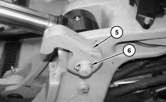
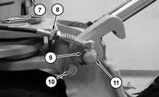
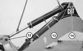
3. Remove clamp (7) (not shown). Loosen nut (8). Remove pin (9) and hook (11). Remove bolt (10).
4. Attach a suitable lifting device to boom cylinder (13). The weight of boom cylinder (13) is approximately 115 kg (255 lb). Remove pin (14). Remove pin (12). Remove boom cylinder (13).
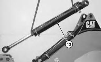
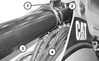
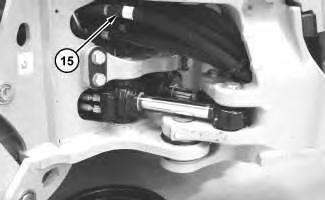
5. Disconnect hose assemblies (15) that are routed to the boom.
g02888098
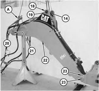
Illustration 9 g02888116
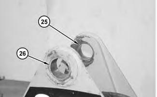
7. Install pin (14) and shims (19). Install retaining ring (18). Install pin assembly (21) (not shown). Install bracket (20) in order to secure pin assembly (21).
8. Attach Tooling (A) and a suitable lifting device to boom (22). The weight of boom (22) is approximately 455 kg (1000 lb).
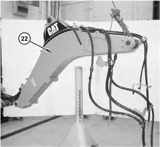
9. Remove bolt (23) and pin (24). Repeat for the other side.
10. Remove boom (22).
