Model KSQ KSQ Terminal Flexibility KSQ terminals are available in a wide array of control packages using pneumatic, electronic analog or factory-installed direct digital (DDC) controls. KSQ units can be provided with an integral sound attenuator for ultra-quiet performance. Low temperature unit construction is also available using 25mm thick matte-faced insulation and isolation of the air valve from the outer casing. Numerous other optional features are available Performance The lack of intruding fasteners, tabs or other obstructions in the air stream results in very quiet sound performance and low internal pressure losses. All units incorporate full 90° rotation round dampers (except the size 600 x 400) for precise control of the airflow. All units are available with pressure independent controls for precise control of the airflow. All units with these controls are factory calibrated for minimum and maximum airflow settings prior to shipment and are easily field adjusted. FloXact-X ™ Air Velocity Sensor • The unique shape, (patent pending) creates a linear amplified signal (at least 2.5x Pdyn) with a low noise level and pressure drop. • Extruded aluminum profile measurement. • Multi point averaging • Measurement according to “Log Tchebycheff” method. • Strengthen measurement signal with at least 2.5x. • Accurate measurement from 1.5m/s air velocity. • Rounded apertures make FloXact™ insensitive to skew or turbulent inflow to 30° in all directions relative to the profile axis. • The units can be supplied with factorysetting with the calibrated analog or digital controllers.
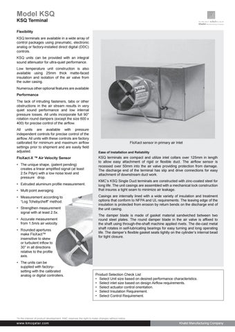
FloXact sensor in primary air Inlet Ease of Installation and Reliability
KSQ terminals are compact and utilize inlet collars over 125mm in length to allow easy attachment of rigid or flexible duct. The airflow sensor is recessed over 50mm into the air valve providing protection from damage. The discharge end of the terminal has slip and drive connections for easy attachment of downstream duct work. KMC’s KSQ Single Duct terminals are constructed with zinc-coated steel for long life. The unit casings are assembled with a mechanical lock construction that insures a tight seam to minimize air leakage. Casings are internally lined with a wide variety of insulation and treatment options that conform to NFPA and UL requirements. The leaving edge of the insulation is protected from erosion by return bends on the discharge end of the unit casing. The damper blade is made of gasket material sandwiched between two round steel plates. The round damper blade in the air valve is affixed to the shaft using through-the-shaft machine applied rivets. The die-cast metal shaft rotates in self-lubricating bearings for easy turning and long operating life. The damper’s flexible gasket seats tightly on the cylinder’s internal bead for tight closure.
Product Selection Check List • Select Unit size based on desired performance characteristics. • Select inlet size based on design Airflow requirements. • Select actuator control orientation. • Select Insulation Requirement. • Select Control Requirement.
*In the interest of product development, KMC reserves the right to make changes without notice.
w ww.kmcq ata r.co m
Khalid Manufacturing Company 1
Model KSQ KSQ Terminal
Air Terminal Casing Treatments KMC’s complete line of casing treatments and insulation systems provide performance solutions to meet any design requirement. We only use insulating materials that meet industry standard classifications for fire, erosion, water vapor sorption, and microbiological resistance.
25mm Matte Face- Black Cloth Under Insulation. Features: • High R-value & Matte face with black cloth Liner. • Isolates glass fibers from the air stream • R Value: 32m.K/W @ 25° C • Density: 48kg/m3
25mm Foil Laminated Fiberglass Insulation Features: • High R-value & impervious foil facing with aluminum taped edges • Isolates glass fibers from the air stream • R Value: 32m.K/W @ 25° C • Density: 48kg/m3
Fiber-Less Insulation
Features: • Closed cell insulation – no glass fibers • 12 mm/25mm Elastomeric Engineered Foam Insulation • R Value: 22 m.K/W @ 20° C • Density: 140-180 kg/m3
Dual-Wall Casing Treatment
Features: • Puncture-proof sheet metal interior skin • Isolates glass fibers from the air stream • 25mm fiberglass insulation between the walls • R Value: 32m.K/W @ 25° C • Density: 48 kg/m3
*In the interest of product development, KMC reserves the right to make changes without notice.
Khalid Manufacturing Company
w w w. k m c qa ta r.co m
Model KSQ KSQ Terminal
Dimensional Data KSQ units
VAV Inlet Size
Flow (max)
ØZ
W1
H1
X
Y
L
S
Wt.
Inches
mm
CFM
CMH
mm
mm
mm
mm
mm
mm
mm
mm
05
125
350
595
124
254
254
197
197
318
136
4.0
06
150
500
850
149
254
254
197
197
318
136
4.0
07
175
675
1147.5
175
305
254
248
197
318
136
5.0
08
200
900
1530
200
305
254
248
197
318
136
5.0
09
225
1100
1870
225
356
318
299
261
368
136
7.0
10
250
1400
2380
251
356
318
299
261
368
136
7.0
12
300
2000
3400
302
406
381
350
324
470
136
8.5
14
350
3000
5100
352
508
445
451
388
470
136
10.5
16
400
4100
6970
403
610
445
553
388
470
136
13.0
24 x 16
600 x 400
7000
11900
610 X 406
965
457
940
432
762
138
36.0
KSQ units with hot water heating coil
Inlet Size
Flow (max)
Outlet Size
1 Row
2 Row
4 Row
Inches
mm
CFM
CMH
W (mm)
H (mm)
L (mm)
Conn. OD mm
Wt. (kg)
L (mm)
Conn. OD mm
Wt. (kg)
L (mm)
Conn. OD mm
Wt. (kg)
05
125
350
595
254
254
413
12.7
6.4
440
12.7
7.3
494
22.2
9.5
06
150
500
850
254
254
413
12.7
6.4
440
12.7
7.3
494
22.2
9.5
07
175
675
1147.5
305
254
413
12.7
7.7
440
12.7
9.1
494
22.2
11.3
08
200
900
1530
305
254
413
12.7
7.7
440
12.7
9.1
494
22.2
11.3
09
225
1100
1870
356
318
464
12.7
10.0
491
12.7
11.8
545
22.2
15.4
10
250
1400
2380
356
318
464
12.7
10.0
491
12.7
11.8
545
22.2
15.4
12
300
2000
3400
406
381
565
22.2
12.7
592
12.7
15.4
646
22.2
19.5
14
350
3000
5100
508
445
565
22.2
15.9
592
22.2
19.5
646
22.2
25.9
16
400
4100
6970
610
445
565
22.2
19.1
592
22.2
22.7
646
22.2
29.9
24 x 16
600 x 400
7000
11900
965
457
889
22.2
45.8
889
22.2
50.8
914
28.6
61.3
*In the interest of product development, KMC reserves the right to make changes without notice.
w ww.kmcq ata r.co m
Khalid Manufacturing Company 3
Model KSQ KSQ Terminal
Dimensional Data KSQA units
VAV Inlet Size
Flow (max)
ØZ
W1
H1
X
Y
L
S
Wt.
Inches
mm
CFM
CMH
mm
mm
mm
mm
mm
mm
mm
mm
05
125
350
595
124
254
254
197
197
1003
136
9.0
06
150
500
850
149
254
254
197
197
1003
136
9.0
07
175
675
1147.5
175
305
254
248
197
1003
136
10.0
08
200
900
1530
200
305
254
248
197
1003
136
10.0
09
225
1100
1870
225
356
318
299
261
1003
136
13.0
10
250
1400
2380
251
356
318
299
261
1003
136
13.0
12
300
2000
3400
302
406
381
350
324
1003
136
14.5
14
350
3000
5100
352
508
445
451
388
1003
136
17.5
16
400
4100
6970
403
610
445
553
388
1003
136
20.0
24 x 16
600 x 400
7000
11900
610 X 406
965
457
940
432
1349
138
49.5
KSQA units with hot water heating coil
Inlet Size
Flow (max)
Outlet Size
1 Row
2 Row
4 Row
Wt. (kg)
L (mm)
Conn. OD mm
Wt. (kg)
L (mm)
Conn. OD mm
Wt. (kg)
11.3
1126
12.7
12.3
1180
22.2
14.5
Inches
mm
CFM
CMH
W (mm)
H (mm)
L (mm)
Conn. OD mm
05
125
350
595
254
254
1099
12.7
06
150
500
850
254
254
1099
12.7
11.3
1126
12.7
12.3
1180
22.2
14.5
07
175
675
1147.5
305
254
1099
12.7
12.7
1126
12.7
14.1
1180
22.2
16.3
08
200
900
1530
305
254
1099
12.7
12.7
1126
12.7
14.1
1180
22.2
16.3
09
225
1100
1870
356
318
1099
12.7
15.9
1126
12.7
17.7
1180
22.2
21.3
10
250
1400
2380
356
318
1099
12.7
15.9
1126
12.7
17.7
1180
22.2
21.3
12
300
2000
3400
406
381
1099
22.2
18.6
1126
12.7
21.3
1180
22.2
25.4
14
350
3000
5100
508
445
1099
22.2
23.1
1126
22.2
26.8
1180
22.2
33.1
16
400
4100
6970
610
445
1099
22.2
26.3
1126
22.2
29.9
1180
22.2
37.2
24 x 16
600 x 400
7000
11900
965
457
1193.8
22.2
59.4
1193.8
22.2
64.4
1219
28.6
74.9
*In the interest of product development, KMC reserves the right to make changes without notice.
Khalid Manufacturing Company
w w w. k m c qa ta r.co m
Model KSQ KSQ Terminal
Dimensional Data KSQE units with Electric heating coil.
VAV Inlet Size
Flow (max)
ØZ
W1
H1
X
Y
L
S
Wt.
Inches
mm
CFM
CMH
mm
mm
mm
mm
mm
mm
mm
mm
05
125
350
595
124
254
254
197
197
1003
136
15.0
06
150
500
850
149
254
254
197
197
1003
136
15.0
07
175
675
1147.5
175
305
254
248
197
1003
136
16.0
08
200
900
1530
200
305
254
248
197
1003
136
16.0
09
225
1100
1870
225
356
318
299
261
1003
136
19.0
10
250
1400
2380
251
356
318
299
261
1003
136
19.0
12
300
2000
3400
302
406
381
350
324
1003
136
21.0
14
350
3000
5100
352
508
445
451
388
1003
136
25.0
16
400
4100
6970
403
610
445
553
388
1003
136
28.0
24 x 16
600 x 400
7000
11900
610 X 406
965
457
940
432
1349
138
58.0
Type
Direct Digital Controller
Inlet Size
Airflow (Min.)
Airflow (Max.)
Wattage (Max)
Volts (V)
Phase
Current (A)
mm
inch
CMH
CFM
CMH
CFM
kW
Volts
(Ø)
Amps
125
5”
85
50
426
251
3
220
1
13.64
150
6”
138
81
695
409
6
415
3
14.43
175
7”
180
106
907
534
6
415
3
14.43
200
8”
255
150
1286
757
6
415
3
14.43
225
9”
323
190
1627
958
8
415
3
19.24
250
10”
398
234
2006
1181
8
415
3
19.24
300
12”
530
312
2672
1573
8
415
3
19.24
350
14”
727
428
3661
2155
11
415
3
26.46
400
16”
990
583
4991
2938
12
415
3
28.87
600 X 400
24” X 16”
1870
1101
9428
5550
16
415
3
38.40
Notes 1. Minimum and maximum values shown are Cu.Mtr / H (CMH ) & Cu.Ft. /min. (CFM) 2. Minimum and maximum airflow with pressure independent controls based on the following. Flow sensor signal : Direct Digital Controllers : 8 Pa (0.03” WG ) - 190 Pa (0.76” WG) 3. Settings below the minimum are not recommended for accurate control when using pressure independent controls. Minimum airflow for pressure dependent applications is O cfm. 4. Pressure independ ent controls may be set for O cfm, at or above the minimum airflow show in table 4, but not between. 5. Direct Digital Controllers are factory programmed. 6. Airflow rates above maximum shown are available. Contact your KMC representative for application assistance.
Electric coil capacity Calculation :
kW = CMH x 1.204 x ΔTA / 3,600 ΔTA = 3,600 x kW / CMH Definitions : CMH = M3 / Hr ΔTA = Differential Air Temperature, ˚C = LAT - EAT LAT = Leaving Air Temperature, ˚C EAT = Entering Air Temperature, ˚C
Example
Design Air Flow LAT EAT ΔTA Electric Coil Capacity =>
1270 32 13 19 (750*1.204*19) 3600 => 8.0
/
CMH ˚C ˚C ˚C kW
*In the interest of product development, KMC reserves the right to make changes without notice.
w ww.kmcq ata r.co m
Khalid Manufacturing Company 5
Model KSQ KSQ Terminal
Selection When selecting KSQ single duct variable air volume terminals, several factors must be considered to make the proper selection including:
in the occupied space, these ratings along with the acoustical environment in which the unit operates, will determine the perceived noise level.
• Air Flow and Air Pressure Drop
Noise generated within the terminal and emitted through the discharge air (discharge sound) will be attenuated by any duct work downstream of the terminal. The noise emitted through the casing of the terminal (radiated sound) will be attenuated by the room’s ceiling. Depending upon the application, either the radiated or discharge noise level will be the relative higher and determine the perceived noise level in the occupied space. The occupied space itself will provide further attenuation depending on the acoustical characteristics of the walls, floors and internal furnishings.
• Sound • Heating (if required) • Controls Air Flow and Air Pressure Drop All KSQ units can operate over a wide range of airflow. The minimum airflow shown for each unit is the lowest airflow at which the airflow sensor can generate an adequately strong signal for the pressure independent controls to operate properly. The maximum airflow shown for each unit is based on the industry practice of limiting the inlet air velocity to reasonable levels.
All manufacturers must make certain assumptions on the acoustical environment of the application and then apply these assumptions to the unit’s sound power ratings to determine the resultant sound pressures and perceived noise level in the occupied space. While the ARI sound power ratings have been certified and can be accurately compared from one manufacturer to another, the NC values predicted will be dependent upon the acoustical assumptions made.
The units selected should be sized where the design airflow is between the maximum and minimum airflows shown in table 4. Referring to table 6 if 2378 CMH (1400 CFM) is the maximum design airflow, a unit with a 300mm inlet can be selected with an air pressure drop of0.01 inches (2.5pa) w.g.
When selecting terminals, check the attenuation assumptions before comparing cataloged NC values. KMC uses the ARI Standard 885, Appendix E attenuation assumptions for determining the anticipated noise levels. The attenuation assumptions in this standard are outlined in Table-2.
Sound Performance Tables 7 thru 11 indicate the sound power levels of each unit at varying air flow rates and inlet static pressures. Disregarding other factors and/or equipment that could contribute to the noise
Table 2: ARI-885 Attenuation Table Octave Band 2
3
4
5
6
7
Radiated
2
1
0
0
0
0
Environmental Effect
All Sizes
16
18
20
26
31
36
Type II Mineral Fiber
18
19
20
26
31
36
Total dB Reduction
Octave Band 2
3
5
4
6
7
Discharge
2
1
0
0
0
0
Environmental Effect
Sizes 5-7
2
4
20
10
20
14
5ft., Duct Lining (12x12)
(300 - 700)
9
5
0
2
0
0
End Reflection
6
10
20
18
21
12
5 ft., 8in. Flex Duct
5
6
8
7
9
10
Room Effect
3
3
3
3
3
3
Sound Power Division
27
29
51
40
53
39
Total dB Reduction
Octave Band 2
3
4
5
6
7
Discharge
2
1
0
0
0
0
Environmental Effect
Sizes 8-24 x 16
2
3
9
18
17
12
5ft., Duct Lining (12x12)
>700)
9
5
2
0
0
0
End Reflection
6
10
18
20
21
12
5 ft., 8in. Flex Duct
5
6
7
8
9
10
Room Effect
5
5
5
5
5
5
Sound Power Division
29
30
41
51
52
39
Total dB Reduction
*In the interest of product development, KMC reserves the right to make changes without notice.
Khalid Manufacturing Company
w w w. k m c qa ta r.co m
Model KSQ KSQ Terminal
Sound Performance The noise level desired in any given space is a function of the activity for which the space is intended. Typical NC design values for various applications are:
Table 3: Typical NC Design Values Hotel Rooms
25 - 35
Offices and conference rooms
25 - 35
Open Offices
30 - 40
Classrooms
Radiated Lw - 1400 CFM @ 2.0” w.g. Inlet Ps 63
125
250
500
Lw Data
----
64
62
54
1000 2000 4000 8000 49
47
42
----
Attenuation
----
18
19
20
26
31
36
----
Plotted Data
----
46
43
34
23
16
6
----
NC
----
27
32
29
21
17
----
----
Discharge Lw - 1400 CFM @ 2.0” w.g. Inlet Ps 63
125
250
500
Lw Data
----
70
71
70
65
64
60
----
35 - 40 (Max)
Attenuation
----
29
30
41
51
52
39
----
Churches
25 - 35
Plotted Data
----
41
41
29
14
12
21
----
Hospital Wards
30 - 40
NC
----
21
30
24
----
----
24
----
Gymnasiums
40 - 45
Libraries
30 - 40
The NC curves are intended to reflect a human’s perceived noise comfort. Plotting the anticipated sound pressure by octave band and determining the tangent NC curve reached throughout all octave bands (using the acoustical assumptions) will indicate the NC value anticipated.
1000 2000 4000 8000
Notes: Size 12 KSQ Radiated sound in the 250hz (third octave) is the Controlling Band
Heating (if Required) Hot water heat Select the hot water coil that provides at least as much heating output as required (based on the design conditions). Using our example of a 300 mm (12”) size unit, if the design heating airflow is 1360 CMH (800 CFM) for the heating coil selection, the heating capacity desired is 8.5 kW (29 MBH), the entering water temperature is 82.3˚C (180 ˚ F) and the entering air temperature is 12.7˚C (55 ˚ F), using Table 14 would indicate that a 1 row coil supplied with 0.25 LPS (4 GPM ) of hot water would be required. The air pressure loss for the heating coil selected at the maximum design airflow for the terminal (2380 CMH i.e 1400 CFM) must be added to the KSQ terminal’s air pressure drop. The heating coil air pressure drops are also shown in Table 6. In our example, the air pressure drop across the coil is 60 Pa (0.24 inches w.g). This would be added to the termin al’s air pressure drop of 2.5 Pa (0.01 inches w.g) at the design maximum airflow of 2380 CMH (1400 CFM) , which results in a Total air pressure drop of 62.5 (0.25 inches w.g). Electric Heat The wattage of electric heat needed is determined by dividing the heating required in Mbh by 3.414, which results in the KW of heating required. Using our example, it would require 8.5 KW of electric heat to provide the 29 Mbh heating capacity. Using table 25, the electric coil with 8.5 KW would be selected. Electric heat can be staged or modulated. Note that the electric coil has an air proving switch, which requires a minimum of .07 inch w.g. Total pressure entering the coil to prove airflow. Also note that it’s prudent to check the air temperature leaving the heating coil at the design airflow. Using the previous example, the resulting leaving air temperature would be approximately 32°C (89°F), which would generally provide a comfortable environment and proper air distribution. Control Sequences A wide array of control sequences are available as standard on KMC‘s KSQ single duct variable air volume terminals.
*In the interest of product development, KMC reserves the right to make changes without notice.
w ww.kmcq ata r.co m
Khalid Manufacturing Company 7
Model KSQ KSQ Terminal
Table 4: Airflow Ranges (FloXactTM Sensor) Type
Direct Digital Controller
Inlet Size
Airflow (Min.)
Airflow (Max.)
mm
inch
CMH
CFM
CMH
CFM
125
5” Dia
85
50
426
251
150
6” Dia
138
81
695
409
175
7” Dia
180
106
907
534
200
8” Dia
255
150
1286
757
225
9” Dia
323
190
1627
958
250
10” Dia
398
234
2006
1181
300
12” Dia
530
312
2672
1573
350
14” Dia
727
428
3661
2155
400
16” Dia
990
583
4991
2938
600 x 400
24 x 16
1870
1101
9428
5550
Notes
1. Minimum and maximum values shown are Cu.Mtr / H (CMH ) & Cu.Ft. /min. (CFM) 2. Minimum and maximum airflow with pressure independent controls based on the following. Flow sensor signal : Direct Digital Controllers : 8 Pa (0.03” WG ) - 190 Pa (0.76” WG) 3. Settings below the minimum are not recommended for accurate control when using pressure independent controls. Minimum airflow for pressure dependent applications is 0 cfm. 4. Pressure independent controls may be set for 0 CFM, at or above the minimum airflow show in table 4, but not between. 5. Direct Digital Controllers are factory programmed. 6. Airflow rates above maximum shown are available. Contact your KMC representative for application assistance.
Table 5: Airflow vs. FloXactTM Sensor Signal SENSOR
INLET SIZE
ΔP
Pa
Inch. w.g
5
6
7
8
9
10
12
14
16
24 x 16
125
150
175
200
225
250
300
350
400
600 x 400
AIR FLOW (CMH)
7
0.03
85
138
180
255
323
398
530
727
990
1870
10
0.04
97
160
207
294
374
460
612
839
1143
2161
15
0.06
119
195
255
360
457
562
749
1028
1400
2645
25
0.1
155
251
330
465
589
727
968
1327
1807
3416
50
0.2
217
357
465
659
834
1028
1369
1875
2557
4830
75
0.3
267
437
569
807
1021
1259
1677
2297
3133
5915
100
0.4
309
505
657
931
1179
1454
1937
2653
3617
6831
125
0.5
345
564
736
1041
1318
1609
2164
2966
4043
7638
149
0.6
377
617
805
1142
1446
1780
2371
3248
4429
8366
174
0.7
408
666
870
1232
1561
1923
2562
3510
4784
9036
199
0.8
437
712
929
1317
1668
2056
2738
3751
5115
9661
224
0.9
462
756
987
1398
1770
2181
2905
3979
5424
10247
249 (K)
1 (K)
488
797
1040
1473
1865
2298
3061
4194
5718
10801
374
1.5
598
975
1274
1804
2285
2815
3749
5137
7002
13228
(sq.Mtr) (sq. ft)
0.012
0.188
0.258
0.338
0.532
0.769
1.05
1.05
1.38
2.67
0.130
0.188
0.258
0.338
0.532
0.769
1.05
1.05
1.38
2.67
Inlet Area
Aiflow Calculations
Example: For a 300 mm (12”) inlet unit with a sensor ΔP signal of 149 Pa ( 0.60 inches w.g) the airflow is calculated to be 2371 CMH. CMH = K( ΔP)^0.5= 3061 (0.6)^0.5 = 2371 ; For a 300mm (12” ) inlet unit with 2371 CMH. the sensor ΔP signal is calculated to be 0.60 inches w.g. ΔP= (CMH/K)^2 = (2371/3061)2 = 0.60” w.g.
Air Flow Sensors Sensor ΔP= (CMH/K)2 CMH = K( ΔP)^0.5
Table 5A: K Factor for FloXactTM Sensor CMH Inlet Size (mm)
125
150
175
200
225
250
300
350
400
600 x 400
K Factor
488
797
1040
1473
1865
2298
3061
4194
5718
10801
Area (Sq.mtr)
0.012
0.017
0.024
0.031
0.040
0.049
0.071
0.098
0.128
0.248
Notes: K factors shown in 1.0 ΔP row *In the interest of product development, KMC reserves the right to make changes without notice.
Khalid Manufacturing Company
w w w. k m c qa ta r.co m
Model KSQ KSQ Terminal
Table 6: Static Pressure Drop Data INLET SIZE mm 125
AIRFLOW
inches
5
150
6
175
7
200
8
225
9
250
10
300
12
350
14
400
16
600 x 400
24x16
CMH 212 297 425 510 595 340 425 510 595 680 849 425 510 680 849 1019 1147 595 807 1019 1189 1359 1529 764 892 1019 1189 1529 1869 934 1147 1359 1699 2039 2378 1359 1699 2039 2378 2888 3398 1784 2378 3058 3737 4417 5096 2378 3228 4077 4926 5946 6965 5096 6795 8494 10193 11891
CFM 125 175 250 300 350 200 250 300 350 400 500 250 300 400 500 600 675 350 475 600 700 800 900 450 525 600 700 900 1100 550 675 800 1000 1200 1400 800 1000 1200 1400 1700 2000 1050 1400 1800 2200 2600 3000 1400 1900 2400 2900 3500 4100 3000 4000 5000 6000 7000
KSQ & A Pa inches w.g. 12.5 0.05 24.9 0.10 37.4 0.15 52.3 0.21 64.7 0.26 2.5 0.01 5.0 0.02 7.5 0.03 10.0 0.04 12.5 0.05 14.9 0.06 2.5 0.01 5.0 0.02 5.0 0.02 7.5 0.03 12.5 0.05 14.9 0.06 2.5 0.01 5.0 0.02 5.0 0.02 7.5 0.03 10.0 0.04 10.0 0.04 2.5 0.01 5.0 0.02 5.0 0.02 7.5 0.03 10.0 0.04 12.5 0.05 2.5 0.01 2.5 0.01 2.5 0.01 2.5 0.01 2.5 0.01 2.5 0.01 2.5 0.01 2.5 0.01 2.5 0.01 2.5 0.01 2.5 0.01 2.5 0.01 2.5 0.01 2.5 0.01 2.5 0.01 2.5 0.01 2.5 0.01 2.5 0.01 2.5 0.01 2.5 0.01 2.5 0.01 2.5 0.01 2.5 0.01 2.5 0.01 2.5 0.01 2.5 0.01 2.5 0.01 2.5 0.01 2.5 0.01
Pa 12.5 24.9 37.4 52.3 64.7 2.5 5.0 7.5 10.0 12.5 14.9 2.5 5.0 5.0 7.5 12.5 14.9 2.5 5.0 5.0 7.5 10.0 10.0 2.5 5.0 5.0 7.5 10.0 12.5 2.5 5.0 5.0 7.5 10.0 14.9 2.5 5.0 5.0 7.5 12.5 14.9 2.5 5.0 5.0 7.5 10.0 12.5 2.5 2.5 5.0 5.0 7.5 10.0 2.5 5.0 7.5 10.0 12.5
KSQE inches w.g. 0.025 0.04 0.05 0.07 0.100 0.040 0.050 0.070 0.100 0.120 0.180 0.040 0.050 0.090 0.130 0.180 0.220 0.070 0.120 0.180 0.240 0.300 0.370 0.060 0.075 0.095 0.120 0.190 0.260 0.080 0.110 0.150 0.230 0.310 0.420 0.090 0.130 0.180 0.240 0.335 0.450 0.075 0.120 0.190 0.270 0.360 0.470 0.085 0.160 0.230 0.320 0.440 0.590 0.150 0.250 0.373 0.510 0.68
MIN ΔPS 1- row Pa inches w.g. 6.2 0.025 10.0 0.04 12.5 0.05 17.4 0.07 24.9 0.100 10.0 0.040 12.5 0.050 17.4 0.070 24.9 0.100 29.9 0.120 44.8 0.180 10.0 0.040 12.5 0.050 22.4 0.090 32.4 0.130 44.8 0.180 54.8 0.220 17.4 0.070 29.9 0.120 44.8 0.180 59.8 0.240 74.7 0.300 92.1 0.370 14.9 0.060 18.7 0.075 23.7 0.095 29.9 0.120 47.3 0.190 64.7 0.260 19.9 0.080 27.4 0.110 37.4 0.150 57.3 0.230 77.2 0.310 104.6 0.420 22.4 0.090 32.4 0.130 44.8 0.180 59.8 0.240 83.4 0.335 112.1 0.450 18.7 0.075 29.9 0.120 47.3 0.190 67.2 0.270 89.6 0.360 117.0 0.470 21.2 0.085 39.8 0.160 57.3 0.230 79.7 0.320 109.6 0.440 146.9 0.590 37.4 0.150 62.3 0.250 92.9 0.373 127.0 0.510 169.3 0.68
Pa 7.5 16.2 27.4 37.4 47.3 17.4 27.4 37.4 47.3 59.8 89.6 19.9 27.4 42.3 64.7 89.6 109.6 34.9 59.8 89.6 117.0 149.4 184.3 29.9 37.4 49.8 62.3 94.6 129.5 39.8 57.3 77.2 114.5 156.9 211.7 42.3 64.7 89.6 117.0 166.8 296.3 37.4 59.8 94.6 132.0 181.8 231.6 44.8 74.7 114.5 159.4 221.6 293.8 74.7 124.5 186.8 255.2 336.2
2- row inches w.g. 0.03 0.065 0.110 0.150 0.190 0.070 0.110 0.150 0.190 0.240 0.360 0.080 0.110 0.170 0.260 0.360 0.440 0.140 0.240 0.360 0.470 0.600 0.740 0.120 0.150 0.200 0.250 0.380 0.520 0.160 0.230 0.310 0.460 0.630 0.850 0.170 0.260 0.360 0.470 0.670 1.190 0.150 0.240 0.380 0.530 0.730 0.930 0.180 0.300 0.460 0.640 0.890 1.180 0.300 0.500 0.750 1.025 1.350
Pa 16.2 28.6 52.3 72.2 94.6 34.9 52.3 72.2 94.6 119.5 174.3 38.6 52.3 87.2 129.5 179.3 216.6 69.7 99.6 179.3 234.1 298.8 368.5 62.3 74.7 97.1 122.0 186.8 261.5 79.7 112.1 151.9 224.1 313.7 423.3 87.2 129.5 179.3 234.1 333.7 443.2 74.7 119.5 189.2 268.9 361.1 463.1 87.2 149.4 226.6 318.7 443.2 587.6 149.4 249.0 368.5 512.2 674.8
4 - row inches w.g. 0.065 0.115 0.210 0.290 0.380 0.140 0.210 0.290 0.380 0.480 0.700 0.155 0.210 0.350 0.520 0.720 0.870 0.280 0.400 0.720 0.940 1.200 1.480 0.250 0.300 0.390 0.490 0.750 1.050 0.320 0.450 0.610 0.900 1.260 1.700 0.350 0.520 0.720 0.940 1.340 1.780 0.300 0.480 0.760 1.080 1.450 1.860 0.350 0.600 0.910 1.280 1.780 2.360 0.600 1.000 1.480 2.057 2.710
Notes
1. Air pressure drops shown for KSQE units with electric coil are for the terminal and electrical coil. 2. Air Pressure drops shown for the hot water coils must be added to the terminal Air pressure drop. 3. Air pressure drop is the difference in the static pressure from the terminal Inlet and discharge with the damper in the fully open position.
*In the interest of product development, KMC reserves the right to make changes without notice.
w ww.kmcq ata r.co m
Khalid Manufacturing Company 9
Model KSQ KSQ Terminal
Table 7: Radiated Sound Power Data (dB) - KSQ units INLET SIZE mm
125
AIRFLOW
inches
5
150
6
175
7
200
8
225
9
250
10
300
12
350
14
400
16
600 x 400
24x16
CMH
CFM
212 297 425 510 595 340 425 510 595 680 849 425 510 680 849 1019 1147 595 807 1019 1189 1359 1529 764 892 1019 1189 1529 1869 934 1147 1359 1699 2039 2378 1359 1699 2039 2378 2888 3398 1784 2378 3058 3737 4417 5096 2378 3228 4077 4926 5946 6965 5096 6795 8494 10193 11891
125 175 250 300 350 200 250 300 350 400 500 250 300 400 500 600 675 350 475 600 700 800 900 450 525 600 700 900 1100 550 675 800 1000 1200 1400 800 1000 1200 1400 1700 2000 1050 1400 1800 2200 2600 3000 1400 1900 2400 2900 3500 4100 3000 4000 5000 6000 7000
125 Pa ( 0.5”) ΔPs Sound Power Levels, dB Octave Band 2 3 4 5 6 7 46 41 33 30 37 24 49 44 35 31 38 25 52 47 39 33 30 26 53 49 41 35 32 27 54 50 44 37 34 32 49 42 35 29 28 27 50 43 36 30 30 28 51 44 37 31 31 29 52 45 39 32 32 30 53 46 41 34 33 31 56 50 45 38 37 35 50 46 38 33 30 26 51 47 39 35 31 27 52 48 40 36 33 28 55 49 42 38 34 30 58 50 45 40 36 31 59 51 47 42 38 32 49 44 36 31 29 29 50 45 37 33 32 30 51 46 39 35 33 31 53 47 41 37 36 32 54 49 44 40 38 33 56 50 47 43 40 35 47 44 37 33 31 26 48 45 38 34 32 27 49 46 39 35 33 28 53 49 41 36 34 29 55 54 45 39 36 31 56 55 48 42 38 33 49 43 38 34 33 28 50 44 40 36 34 29 51 46 41 37 35 30 52 48 44 39 37 31 55 51 46 41 39 34 57 53 49 44 41 36 51 44 37 34 33 27 52 45 38 35 34 29 53 47 40 37 35 30 54 48 42 39 36 31 56 51 45 42 39 32 58 53 49 45 42 35 51 44 36 35 34 30 52 45 39 36 36 31 54 48 41 38 37 32 56 51 45 41 39 35 59 54 48 44 42 37 61 56 51 47 45 40 50 45 38 36 37 32 52 47 40 38 38 33 55 50 43 41 40 36 58 52 45 43 41 38 61 55 48 45 43 40 64 58 52 48 45 42 61 54 49 44 40 35 66 59 55 48 44 38 70 63 59 53 48 41 73 67 63 56 51 44 76 70 66 59 54 46
250 Pa (1.0”) ΔPs Sound Power Levels, dB Octave Band 2 3 4 5 6 7 51 43 39 34 33 27 52 48 41 37 35 28 55 51 44 38 36 29 56 53 46 40 37 30 58 55 48 41 39 34 52 47 40 34 34 31 53 48 41 35 35 32 54 49 42 36 36 33 55 50 43 37 37 34 56 51 44 38 38 35 58 53 48 40 40 38 52 51 44 39 36 31 53 55 46 40 37 32 56 56 48 42 39 33 57 57 49 43 40 34 60 58 50 44 41 35 61 59 51 45 42 36 53 50 43 38 36 34 54 51 44 39 37 35 55 52 45 40 38 36 56 53 46 41 39 37 57 54 47 43 41 38 59 55 49 45 43 39 51 52 43 38 36 31 52 53 44 39 37 32 53 54 45 40 38 33 54 55 46 41 39 34 55 56 48 43 40 35 56 57 50 44 41 36 52 51 43 40 39 35 53 52 44 41 40 36 54 53 45 42 41 37 55 54 47 43 42 38 57 55 49 45 43 39 59 56 52 48 46 40 56 50 43 39 39 33 57 51 44 40 40 34 58 52 45 41 41 35 59 53 46 43 42 36 60 55 48 45 43 37 62 57 51 47 45 38 57 52 42 39 39 36 58 53 43 40 40 37 59 54 45 43 42 38 60 55 47 44 44 39 62 57 50 46 45 41 64 59 53 49 47 43 57 53 44 41 40 37 58 54 45 42 41 38 60 55 46 45 44 39 62 57 48 46 46 41 64 59 51 48 47 42 66 61 54 50 49 44 65 57 52 48 44 38 69 62 56 51 46 41 73 65 60 54 51 45 75 69 63 56 62 47 78 71 66 58 54 50
500 Pa (2.0”) ΔPs Sound Power Levels, dB Octave Band 2 3 4 5 6 7 50 46 43 39 38 33 54 51 47 42 40 34 58 56 50 45 43 35 60 57 52 46 44 36 62 58 54 47 45 38 52 49 46 39 40 37 55 53 48 41 41 38 57 55 49 42 42 39 58 56 50 43 43 40 60 57 51 44 44 41 62 58 53 46 45 42 52 52 48 43 41 36 53 55 50 45 43 38 56 62 54 49 45 40 59 65 58 52 47 41 61 66 59 53 48 42 64 67 60 54 49 43 54 55 50 45 43 40 56 60 51 46 44 41 58 61 52 47 45 41 60 62 53 48 45 42 61 63 54 49 46 43 63 64 55 50 47 44 55 58 51 45 43 38 57 59 52 46 44 39 58 60 53 47 45 40 59 61 54 48 46 41 60 62 55 49 47 42 61 63 56 50 48 44 54 57 50 46 45 40 56 58 51 47 46 41 57 59 52 48 47 42 59 60 53 49 48 43 61 61 54 50 49 44 63 62 55 51 50 45 60 59 51 46 44 39 62 60 52 47 45 40 63 61 53 48 46 41 64 62 54 49 47 42 65 63 55 50 48 43 67 64 56 51 49 44 61 60 51 47 45 42 63 61 52 48 46 43 64 62 53 49 47 44 65 63 54 50 49 45 66 64 55 51 50 46 68 64 56 52 52 47 61 61 51 48 46 42 64 62 52 49 47 43 65 63 53 50 48 44 67 64 54 51 50 46 68 65 55 52 51 47 69 66 56 53 52 48 71 64 58 53 50 44 74 67 60 55 51 45 77 69 63 58 53 47 79 70 64 59 54 48 81 72 66 60 55 49
750 Pa (3.0”) ΔPs Sound Power Levels, dB Octave Band 2 3 4 5 6 7 50 47 44 42 42 37 54 52 49 45 44 38 58 58 53 48 46 39 60 60 55 50 48 40 62 61 58 51 49 41 53 50 48 42 43 40 55 53 51 44 44 41 57 56 53 46 45 42 59 59 55 48 46 43 60 61 56 49 47 44 63 62 57 50 49 45 52 53 49 46 44 41 54 56 52 48 45 42 57 61 56 51 48 43 59 66 60 55 50 45 61 69 63 58 52 46 63 70 65 60 53 47 55 55 52 48 47 44 57 60 56 51 48 44 59 64 58 52 49 45 60 65 59 53 50 46 62 66 60 54 50 47 63 67 61 55 51 47 57 63 55 49 47 42 58 66 57 50 48 43 59 67 58 51 49 44 60 68 59 52 50 45 61 69 60 53 51 46 63 70 61 54 52 47 55 61 53 51 48 43 56 62 54 51 49 44 58 63 55 52 50 45 60 64 56 53 51 46 62 65 57 53 52 47 65 66 58 54 53 48 60 60 57 50 48 43 62 62 58 51 49 44 64 63 59 52 50 45 66 64 59 53 51 46 68 65 60 54 52 47 69 66 60 55 53 48 61 63 55 50 49 45 64 64 56 51 50 46 66 65 57 52 51 47 67 66 58 53 52 48 69 67 59 54 53 49 70 68 60 55 54 50 63 64 55 51 50 46 65 64 56 52 51 47 67 65 47 53 52 48 69 67 58 54 53 49 70 68 59 55 54 50 71 69 60 56 55 51 73 68 63 57 53 48 76 70 64 58 54 49 79 72 65 59 56 50 81 73 66 60 57 51 83 74 67 61 58 52
Notes 1. All sound data are measured in accordance with industry standard ARI-880. 2. Sound power levels are in decibels, re 10-12 watts
*In the interest of product development, KMC reserves the right to make changes without notice.
Khalid Manufacturing Company
w w w. k m c qa ta r.co m
Model KSQ KSQ Terminal
Table 8: Discharge Sound Power Data (dB) - KSQ units. Foil Faced Insulation - 25mm (1”) Thk. INLET SIZE mm
125
AIRFLOW
inches
5
150
6
175
7
200
8
225
9
250
10
300
12
350
14
400
16
CMH
CFM
212 297 425 510 595 340 425 510 595 680 849 425 510 680 849 1019 1147 595 807 1019 1189 1359 1529 764 892 1019 1189 1529 1869 934 1147 1359 1699 2039 2378 1359 1699 2039 2378 2888 3398 1784 2378 3058 3737 4417 5096 2378 3228 4077 4926 5946 6965
125 175 250 300 350 200 250 300 350 400 500 250 300 400 500 600 675 350 475 600 700 800 900 450 525 600 700 900 1100 550 675 800 1000 1200 1400 800 1000 1200 1400 1700 2000 1050 1400 1800 2200 2600 3000 1400 1900 2400 2900 3500 4100
125 Pa ( 0.5”) ΔPs Sound Power Levels, dB Octave Band 2 3 4 5 6 7 57 53 45 42 40 38 59 57 48 44 42 39 62 59 51 48 45 42 63 60 53 49 47 44 64 61 55 53 49 47 59 56 48 48 45 41 60 59 50 49 46 42 61 61 51 50 46 43 63 62 52 51 47 44 65 64 56 53 47 46 68 66 59 58 49 49 59 52 46 46 43 42 60 56 48 47 44 45 61 59 50 49 45 46 62 61 53 51 47 49 64 62 57 55 48 50 67 64 60 58 49 51 61 56 48 49 47 45 62 57 50 50 48 47 63 60 52 52 49 48 64 62 55 54 51 50 66 64 57 57 52 51 68 65 61 59 53 52 58 54 48 47 46 44 59 56 49 49 47 45 60 57 50 50 48 46 61 58 51 51 49 47 62 60 54 52 50 48 66 63 59 58 51 49 56 57 50 50 49 46 58 59 51 51 59 47 60 60 53 52 51 48 61 63 55 55 52 49 63 66 58 57 53 50 65 67 61 59 55 53 59 56 51 52 49 48 60 57 53 53 50 48 61 58 55 54 51 49 62 60 56 55 53 50 65 62 60 56 54 52 67 64 63 58 56 53 59 54 52 53 51 48 61 56 54 54 52 49 64 59 56 55 53 59 67 63 60 57 54 53 70 66 63 59 56 55 72 68 66 62 58 57 59 53 51 52 59 48 61 55 54 53 51 50 64 58 56 54 53 51 67 61 59 56 54 52 71 64 63 59 56 55 73 67 69 61 59 58
250 Pa (1.0”) ΔPs Sound Power Levels, dB Octave Band 2 3 4 5 6 7 60 56 52 49 48 48 62 60 53 51 49 49 65 63 56 53 50 50 66 65 58 54 51 51 69 66 60 56 53 53 64 63 55 54 52 51 65 65 56 55 53 52 66 67 57 56 54 53 67 68 58 57 55 53 68 69 60 58 55 54 71 70 63 60 55 54 62 60 54 51 50 51 64 62 55 52 50 53 65 65 56 54 50 54 66 66 57 55 52 55 67 67 60 58 53 56 69 68 63 60 54 57 65 64 56 55 53 52 67 65 57 56 54 53 68 66 58 57 55 54 69 67 59 58 56 55 70 68 61 60 57 56 71 69 63 61 58 57 64 62 55 53 52 53 65 63 56 54 53 54 66 64 57 55 54 55 67 65 58 56 55 55 68 66 59 57 56 56 68 67 62 59 57 56 62 64 59 56 55 55 63 65 60 57 56 56 64 66 62 58 57 57 65 67 62 60 58 57 66 69 63 61 59 58 67 70 65 62 60 58 65 62 59 57 55 56 66 63 60 58 56 57 67 66 61 59 57 57 69 67 62 60 58 58 71 68 65 62 59 59 72 70 66 63 60 60 67 63 60 57 56 57 68 64 61 58 57 58 69 65 62 59 58 59 70 66 65 60 59 60 71 67 67 61 60 61 74 70 69 63 62 62 65 61 58 57 56 59 67 62 60 58 58 60 68 64 61 59 59 61 71 65 63 61 60 62 74 68 66 62 61 63 76 70 70 64 62 64
500 Pa (2.0”) ΔPs Sound Power Levels, dB Octave Band 2 3 4 5 6 7 60 61 57 56 55 57 65 66 60 57 55 57 69 68 62 58 56 58 71 69 63 59 56 58 72 70 65 59 56 60 65 68 62 59 58 58 68 71 63 60 59 59 69 72 64 61 60 60 71 73 65 62 60 60 72 74 66 63 60 60 75 76 68 64 61 61 64 64 63 58 56 57 67 66 63 59 58 58 69 70 64 60 59 59 70 72 65 61 59 60 72 73 66 63 59 61 73 74 67 64 59 62 67 70 65 63 60 59 71 71 65 63 61 60 72 74 65 63 62 61 73 75 66 64 62 62 74 76 67 65 63 62 75 77 68 66 63 62 67 71 63 62 60 60 69 71 64 62 60 61 71 72 64 62 61 62 72 72 64 62 61 62 73 73 65 62 62 62 74 74 66 65 63 64 67 74 67 67 64 62 69 74 68 66 64 63 70 74 68 66 65 64 71 74 68 66 65 64 72 75 69 67 66 65 73 76 70 68 66 65 73 72 68 65 66 64 75 73 69 65 66 64 76 74 70 65 66 64 77 75 71 66 67 65 78 76 72 68 68 66 78 75 73 69 69 66 72 71 67 65 64 64 73 72 68 66 65 65 74 73 69 67 66 65 76 74 70 68 67 67 77 73 71 69 68 68 78 74 72 70 69 69 72 69 67 63 63 65 73 70 68 64 64 66 74 71 69 65 65 66 76 72 70 66 66 67 78 73 71 67 66 68 80 75 73 69 68 69
750 Pa (3.0”) ΔPs Sound Power Levels, dB Octave Band 2 3 4 5 6 7 59 61 59 57 59 60 64 68 64 60 60 61 69 72 66 61 60 62 72 72 67 62 60 63 74 72 68 63 60 63 64 67 64 63 60 61 68 73 68 64 61 62 70 75 69 65 62 63 72 76 70 66 63 64 73 77 71 67 64 64 76 79 72 68 66 65 65 67 63 62 60 62 67 68 65 63 61 63 70 71 67 64 62 66 72 74 69 65 62 66 74 76 70 67 63 66 75 77 71 68 64 66 68 73 68 67 64 63 72 75 70 68 65 64 73 78 71 69 66 66 74 79 72 69 66 66 76 80 73 70 67 66 77 81 74 71 68 66 69 70 69 66 64 65 71 72 69 67 64 66 72 74 70 68 65 66 73 75 70 68 65 66 75 76 71 69 66 67 77 78 72 69 67 69 68 76 72 69 68 67 70 77 72 70 68 68 71 78 73 71 69 68 73 78 73 71 69 68 74 79 73 71 70 69 75 80 74 72 70 70 74 75 73 70 67 68 75 76 73 70 68 68 76 77 74 70 69 69 77 78 74 70 70 69 78 79 74 71 71 70 79 80 75 73 72 71 74 74 72 69 67 69 75 75 73 70 68 70 76 76 74 71 69 70 77 77 75 72 70 71 78 78 76 73 71 72 80 79 77 74 72 70 73 74 71 68 67 70 75 75 73 69 68 70 77 76 74 70 69 71 79 77 74 70 70 72 81 78 75 71 70 73 82 79 76 72 71 73
Notes 1. All sound data are measured in accordance with industry standard ARI-880. 2. Sound power levels are in decibels, re 10-12 watts.
*In the interest of product development, KMC reserves the right to make changes without notice.
w ww.kmcq ata r.co m
Khalid Manufacturing Company 11
Model KSQ KSQ Terminal
Table 9: Discharge Sound Power Data (dB) - KSQ units. Dual Wall Metal Liner INLET SIZE mm
125
AIRFLOW
inches
5
150
6
175
7
200
8
225
9
250
10
300
12
350
14
400
16
CMH
CFM
212 297 425 510 595 340 425 510 595 680 849 425 510 680 849 1019 1147 595 807 1019 1189 1359 1529 764 892 1019 1189 1529 1869 934 1147 1359 1699 2039 2378 1359 1699 2039 2378 2888 3398 1784 2378 3058 3737 4417 5096 2378 3228 4077 4926 5946 6965
125 175 250 300 350 200 250 300 350 400 500 250 300 400 500 600 675 350 475 600 700 800 900 450 525 600 700 900 1100 550 675 800 1000 1200 1400 800 1000 1200 1400 1700 2000 1050 1400 1800 2200 2600 3000 1400 1900 2400 2900 3500 4100
125 Pa ( 0.5”) ΔPs Sound Power Levels, dB Octave Band 2 3 4 5 6 7 57 52 45 42 40 36 59 56 48 45 42 39 62 59 52 49 46 43 63 60 53 51 49 45 64 61 56 54 54 51 59 56 48 47 44 41 60 58 59 49 46 42 61 60 52 51 47 43 63 62 53 53 49 45 65 64 56 55 50 47 68 66 60 59 54 52 59 55 47 45 42 39 60 56 48 46 44 41 61 59 50 49 46 44 62 61 54 52 48 48 64 62 58 55 59 49 67 64 61 58 52 50 61 56 48 48 45 41 62 57 50 50 48 44 63 60 53 52 50 47 64 62 56 55 52 49 66 64 59 57 54 50 68 65 62 59 56 52 58 53 49 49 48 44 59 55 50 50 49 45 60 56 51 51 50 46 61 57 52 52 51 47 62 60 54 54 52 48 66 63 59 59 53 51 56 56 51 51 50 46 58 58 53 53 51 45 60 60 54 54 52 47 61 63 56 56 53 50 63 65 59 58 55 52 65 67 62 61 57 54 59 55 51 52 51 45 60 56 52 52 53 46 61 57 54 54 52 47 62 61 58 56 55 48 65 64 61 59 57 50 67 66 64 61 59 55 59 54 51 53 54 47 61 57 56 56 55 50 64 60 57 57 56 52 67 62 59 58 57 54 70 63 63 60 59 56 72 65 66 63 62 58 59 53 51 52 52 48 61 55 54 54 54 51 64 59 56 55 55 52 67 62 59 57 56 53 71 66 63 60 59 56 73 69 69 64 62 59
250 Pa (1.0”) ΔPs Sound Power Levels, dB Octave Band 2 3 4 5 6 7 59 56 56 47 46 45 62 60 60 51 48 46 65 63 63 53 50 48 66 65 65 55 51 49 69 66 66 56 54 53 63 63 6 53 51 48 65 65 56 54 52 49 66 67 57 56 54 50 67 68 58 57 55 51 68 69 60 59 56 53 71 70 63 62 58 55 63 60 54 51 50 49 64 62 55 52 51 51 65 65 56 54 52 53 66 66 57 56 53 54 67 67 60 58 54 55 69 68 63 61 56 56 66 64 56 55 53 50 67 65 57 56 54 51 68 66 58 57 55 53 69 67 59 59 57 54 70 68 61 69 58 55 71 69 63 62 59 57 65 62 55 53 53 51 66 63 56 54 54 52 67 64 57 55 55 53 68 65 58 57 56 55 68 66 59 58 57 56 69 67 62 61 58 57 63 64 59 56 56 53 64 65 60 57 57 54 65 66 62 59 58 55 66 67 62 60 59 57 67 69 63 62 61 58 68 70 65 64 62 59 66 62 59 57 56 53 68 63 60 58 57 54 70 66 61 59 58 55 69 67 62 60 59 57 70 68 65 61 60 58 70 70 66 64 61 59 68 63 60 57 58 56 69 64 61 59 59 57 71 65 62 60 60 59 72 66 65 61 61 61 74 67 67 63 62 62 75 70 69 64 63 63 66 61 58 57 57 56 67 62 60 59 59 57 69 64 61 60 60 58 71 65 63 61 61 59 73 68 66 64 63 61 76 70 70 66 65 62
500 Pa (2.0”) ΔPs Sound Power Levels, dB Octave Band 2 3 4 5 6 7 59 57 53 53 55 53 64 64 58 55 55 54 69 67 61 58 56 55 71 69 63 59 56 56 72 70 65 61 58 59 64 63 60 59 58 55 68 68 63 60 59 56 69 71 64 61 60 57 71 72 65 62 61 58 72 73 66 64 62 59 75 76 68 66 63 60 64 63 61 58 57 57 67 66 62 59 58 58 69 70 64 60 59 59 70 72 65 62 59 60 72 73 66 63 60 60 73 74 67 64 60 61 67 69 63 63 61 58 71 71 64 63 62 59 72 74 65 63 62 60 73 75 66 64 62 60 74 76 67 65 63 61 75 77 68 66 64 62 68 68 61 58 58 58 69 70 62 59 59 59 71 71 63 60 60 60 72 72 64 61 61 60 73 73 65 62 62 62 74 74 66 65 64 63 67 71 65 62 62 60 69 72 66 63 63 61 70 73 67 64 64 62 71 74 68 65 64 62 72 75 69 66 66 64 73 76 70 68 67 65 72 70 68 62 63 59 73 71 69 63 64 60 74 72 70 64 65 61 75 73 71 65 66 62 76 75 72 66 67 63 77 75 73 67 68 64 71 69 67 66 63 62 72 70 68 67 64 63 73 72 69 68 65 64 75 73 69 69 66 65 76 74 70 70 67 66 78 75 71 71 68 67 72 69 67 64 64 63 73 70 68 65 65 64 74 71 69 66 66 65 76 63 70 67 67 66 79 75 71 68 68 67 80 77 73 70 79 68
750 Pa (3.0”) ΔPs Sound Power Levels, dB Octave Band 2 3 4 5 6 7 59 58 56 56 59 59 64 64 60 59 69 59 69 69 64 60 60 60 72 71 66 62 60 61 74 72 68 64 61 62 64 64 61 62 61 59 68 68 64 64 62 60 70 72 67 65 63 61 72 75 69 66 64 62 73 77 71 67 65 63 76 79 72 69 66 64 65 63 62 62 62 62 67 66 64 63 62 63 70 71 67 64 63 64 72 74 69 66 63 65 74 76 70 67 63 65 75 77 71 68 63 66 68 69 67 67 66 63 72 74 69 68 66 64 73 78 71 68 67 65 74 79 72 69 67 65 76 80 73 70 67 65 77 81 74 71 67 66 69 69 66 64 63 63 71 71 67 64 63 63 72 72 68 65 64 64 73 75 69 66 64 65 75 76 70 67 65 66 77 78 71 67 67 67 68 75 69 67 67 65 70 76 70 67 67 65 71 77 71 68 68 66 73 78 72 69 68 67 74 79 73 70 69 68 75 80 73 71 70 68 73 73 70 68 68 67 75 74 71 69 69 68 76 76 72 70 70 69 77 77 73 70 71 69 78 78 74 71 72 70 79 79 75 72 72 70 72 73 70 68 68 67 75 74 71 70 69 69 76 75 72 71 70 69 77 76 73 72 71 71 78 77 74 73 72 72 80 78 75 74 73 73 74 73 70 68 68 68 75 74 72 69 69 68 77 75 73 70 70 69 79 76 74 71 71 70 81 78 75 72 72 71 82 81 77 74 73 72
Notes 1. All sound data are measured in accordance with industry standard ARI-880. 2. Sound power levels are in decibels, re 10-12 watts.
*In the interest of product development, KMC reserves the right to make changes without notice.
Khalid Manufacturing Company
w w w. k m c qa ta r.co m
Model KSQ KSQ Terminal
Table 10: Radiated Sound Power Data (dB) - KSQA units with integral Sound attenuator and KSQE units with integral electric heat INLET SIZE mm
125
AIRFLOW
inches
5
150
6
175
7
200
8
225
9
250
10
300
12
350
14
400
16
600 x 400
24x16
CMH
CFM
212 297 425 510 595 340 425 510 595 680 849 425 510 680 849 1019 1147 595 807 1019 1189 1359 1529 764 892 1019 1189 1529 1869 934 1147 1359 1699 2039 2378 1359 1699 2039 2378 2888 3398 1784 2378 3058 3737 4417 5096 2378 3228 4077 4926 5946 6965 5096 6795 8494 10193 11891
125 175 250 300 350 200 250 300 350 400 500 250 300 400 500 600 675 350 475 600 700 800 900 450 525 600 700 900 1100 550 675 800 1000 1200 1400 800 1000 1200 1400 1700 2000 1050 1400 1800 2200 2600 3000 1400 1900 2400 2900 3500 4100 3000 4000 5000 6000 7000
125 Pa ( 0.5”) ΔPs Sound Power Levels, dB Octave Band 2 3 4 5 6 7 46 41 33 30 27 24 49 44 35 31 28 25 52 47 39 33 30 26 53 49 41 35 32 27 54 50 44 37 34 32 49 42 35 29 28 27 50 43 36 30 30 28 51 44 37 31 31 29 52 45 39 32 32 30 53 46 41 34 33 31 56 50 45 38 37 35 50 46 38 33 30 26 51 47 39 35 31 27 52 48 40 36 33 28 55 49 42 38 34 30 58 50 45 40 36 31 59 51 47 42 38 32 49 44 36 31 29 29 50 45 37 33 32 30 51 46 39 35 33 31 53 47 41 37 36 32 54 49 44 40 38 33 56 50 47 43 40 35 47 44 37 33 31 26 48 45 38 34 32 27 49 46 39 35 33 28 53 49 41 36 34 29 55 54 45 39 36 31 56 55 48 42 38 33 49 43 38 34 33 28 50 44 40 36 34 29 51 46 41 37 35 30 52 48 44 39 37 31 55 51 46 41 39 34 57 53 49 44 41 36 51 44 37 34 33 27 52 45 38 35 34 29 53 47 40 37 35 30 54 48 42 39 36 31 56 51 45 42 39 32 58 53 49 45 42 35 51 44 36 35 34 30 52 45 39 36 36 31 54 48 41 38 37 32 56 51 45 41 39 35 59 54 48 44 42 37 61 56 51 47 45 40 50 45 38 36 37 32 52 47 40 38 38 33 55 50 43 41 40 36 58 52 45 43 41 38 61 55 48 45 43 40 64 58 52 48 45 42 61 54 49 44 40 35 66 59 55 48 44 38 70 63 59 53 48 41 73 67 63 56 51 44 76 70 66 59 54 46
250 Pa (1.0”) ΔPs Sound Power Levels, dB Octave Band 2 3 4 5 6 7 51 43 39 34 33 27 52 48 41 37 35 28 55 51 44 38 36 29 56 53 46 40 37 30 58 55 48 41 39 34 52 47 40 34 34 31 53 48 41 35 35 32 54 49 42 36 36 33 55 50 43 37 37 34 56 51 44 38 38 35 58 53 48 40 40 38 52 51 44 39 36 31 53 55 46 40 37 32 56 56 48 42 39 33 57 57 49 43 40 34 60 58 50 44 41 35 61 59 51 45 42 36 53 50 43 38 36 34 54 51 44 39 37 35 55 52 45 40 38 36 56 53 46 41 39 37 57 54 47 43 41 38 59 55 49 45 43 39 51 52 43 38 36 31 52 53 44 39 37 32 53 54 45 40 38 33 54 55 46 41 39 34 55 56 48 43 40 35 56 57 50 44 41 36 52 51 43 40 39 35 53 52 44 41 40 36 54 53 45 42 41 37 55 54 47 43 42 38 57 55 49 45 43 39 59 56 52 48 46 40 56 50 43 39 39 33 57 51 44 40 40 34 58 52 45 41 41 35 59 53 46 43 42 36 60 55 48 45 43 37 62 57 51 47 45 38 57 52 42 39 39 36 58 53 43 40 40 37 59 54 45 43 42 38 60 55 47 44 44 39 62 57 50 46 45 41 64 59 53 49 47 43 57 53 44 41 40 37 58 54 45 42 41 38 60 55 46 45 44 39 62 57 48 46 46 41 64 59 51 48 47 42 66 61 54 50 49 44 65 57 52 48 44 38 69 62 56 51 46 41 73 65 60 54 51 45 75 69 63 56 52 47 78 71 66 58 54 50
500 Pa (2.0”) ΔPs Sound Power Levels, dB Octave Band 2 3 4 5 6 7 50 46 43 39 38 33 54 51 47 42 40 34 58 56 50 45 43 35 60 57 52 46 44 36 62 58 54 47 45 38 52 49 46 39 40 37 55 53 48 41 41 38 57 55 49 42 42 39 58 56 50 43 43 40 60 57 51 44 44 41 62 58 53 46 45 42 52 52 48 43 41 36 53 55 50 45 43 38 56 62 54 49 45 40 59 65 58 52 47 41 61 66 59 53 48 42 64 67 60 54 49 43 54 55 50 45 43 40 56 60 51 46 44 41 58 61 52 47 45 41 60 62 53 48 45 42 61 63 54 49 46 43 63 64 55 50 47 44 55 58 51 45 43 38 57 59 52 46 44 39 58 60 53 47 45 40 59 61 54 48 46 41 60 62 55 49 47 42 61 63 56 50 48 44 54 57 50 46 45 40 56 58 51 47 46 41 57 59 52 48 47 42 59 60 53 49 48 43 61 61 54 50 49 44 63 62 55 51 50 45 60 59 51 46 44 39 62 60 52 47 45 40 63 61 53 48 46 41 64 62 54 49 47 42 65 63 55 50 48 43 67 64 56 51 49 44 61 60 51 47 45 42 63 61 52 48 46 43 64 62 53 49 47 44 65 63 54 50 49 45 66 64 55 51 50 46 68 64 56 52 52 47 61 61 51 48 46 42 64 62 52 49 47 43 65 63 53 50 48 44 67 64 54 51 50 46 68 65 55 52 51 47 69 66 56 53 52 48 71 64 58 53 50 44 74 67 60 55 51 45 77 69 63 58 53 47 79 70 64 59 54 48 81 72 66 60 55 49
750 Pa (3.0”) ΔPs Sound Power Levels, dB Octave Band 2 3 4 5 6 7 50 47 44 42 42 37 54 52 49 45 44 38 58 58 53 48 46 39 60 60 55 50 48 40 62 61 58 51 49 41 52 50 48 42 43 40 55 53 51 44 44 41 57 56 53 46 45 42 58 59 55 48 46 43 60 61 57 49 47 44 62 62 57 50 49 45 52 53 49 46 44 41 53 56 52 48 45 42 56 61 56 51 48 43 59 66 60 55 50 45 61 69 63 58 52 46 64 70 65 60 53 47 54 55 52 48 47 44 56 60 56 51 48 44 58 64 58 52 49 45 60 65 59 53 59 46 61 66 60 54 50 47 63 67 61 55 51 47 55 63 55 49 47 42 57 66 57 50 48 43 58 67 58 51 49 44 59 68 59 52 50 45 60 69 60 53 51 46 61 70 61 54 52 47 54 61 53 51 48 43 56 62 54 51 49 44 57 63 55 52 50 45 59 64 56 53 51 46 61 65 57 53 52 47 63 66 58 54 53 48 60 60 57 50 48 43 62 62 58 51 49 44 63 63 59 52 50 45 64 64 59 53 51 46 65 65 60 54 52 47 67 66 60 55 53 48 61 63 55 50 49 45 63 64 56 51 50 46 64 65 57 52 51 47 65 66 58 53 52 48 66 67 59 54 53 49 68 68 60 55 54 50 61 64 55 51 50 46 64 64 56 52 51 47 65 65 57 53 52 48 67 67 58 54 53 49 68 68 59 55 54 50 69 69 60 56 55 51 71 68 63 57 53 48 74 70 64 58 54 49 77 72 65 59 56 50 79 73 66 60 57 51 81 74 67 61 58 52
Notes 1. All sound data are measured in accordance with industry standard ARI-880. 2. Sound power levels are in decibels, re 10-12 watts.
*In the interest of product development, KMC reserves the right to make changes without notice.
w ww.kmcq ata r.co m
Khalid Manufacturing Company 13
Model KSQ KSQ Terminal
Table 11 : Discharge Sound Power Data (dB)- KSQA units with integral sound attenuator and KSQE units with integral electric heat - 25mm (1”) Foil Faced Insulation. INLET SIZE mm
125
AIRFLOW
inches
5
150
6
175
7
200
8
225
9
250
10
300
12
350
14
400
16
CMH
CFM
212 297 425 510 595 340 425 510 595 680 849 425 510 680 849 1019 1147 595 807 1019 1189 1359 1529 764 892 1019 1189 1529 1869 934 1147 1359 1699 2039 2378 1359 1699 2039 2378 2888 3398 1784 2378 3058 3737 4417 5096 2378 3228 4077 4926 5946 6965
125 175 250 300 350 200 250 300 350 400 500 250 300 400 500 600 675 350 475 600 700 800 900 450 525 600 700 900 1100 550 675 800 1000 1200 1400 800 1000 1200 1400 1700 2000 1050 1400 1800 2200 2600 3000 1400 1900 2400 2900 3500 4100
125 Pa ( 0.5”) ΔPs Sound Power Levels, dB Octave Band 2 3 4 5 6 7 59 53 46 40 31 28 62 58 48 42 33 29 65 61 51 45 36 31 66 63 54 47 37 31 68 65 57 49 40 38 62 55 48 42 33 28 62 59 49 43 34 29 63 61 51 45 35 30 65 62 52 47 36 31 65 62 53 48 37 31 69 65 59 52 40 37 61 56 50 44 35 31 62 58 50 44 35 32 62 61 51 46 37 34 64 62 53 48 38 35 66 63 56 52 40 37 68 64 59 54 41 38 61 53 49 44 37 34 62 56 51 46 38 34 64 58 52 48 40 35 66 60 54 49 41 37 67 62 56 51 42 38 68 63 57 53 43 39 57 57 49 45 40 37 59 58 51 45 41 38 61 59 52 47 42 39 63 62 53 48 43 40 65 64 55 51 44 42 66 64 58 54 46 43 57 57 49 45 40 37 60 58 53 47 44 40 62 61 54 49 45 42 63 63 55 51 46 44 65 64 58 53 48 45 67 66 60 56 49 46 56 53 51 47 46 43 60 56 53 49 47 45 64 60 54 50 48 46 65 61 56 51 49 47 67 63 58 56 50 48 69 65 61 57 52 50 61 58 53 50 49 47 65 60 56 52 51 48 68 63 58 55 52 49 69 63 59 56 53 51 71 65 61 56 54 51 73 67 64 59 56 53 61 58 53 50 49 47 65 61 56 53 53 51 67 62 58 55 53 52 70 64 60 56 54 53 73 67 62 58 56 54 75 69 67 60 58 56
250 Pa (1.0”) ΔPs Sound Power Levels, dB Octave Band 2 3 4 5 6 7 59 56 56 47 46 45 62 60 60 51 48 46 65 63 63 53 50 48 66 65 65 55 51 49 69 66 66 56 54 53 63 63 6 53 51 48 65 65 56 54 52 49 66 67 57 56 54 50 67 68 58 57 55 51 68 69 60 59 56 53 71 70 63 62 58 55 63 60 54 51 50 49 64 62 55 52 51 51 65 65 56 54 52 53 66 66 57 56 53 54 67 67 60 58 54 55 69 68 63 61 56 56 66 64 56 55 53 50 67 65 57 56 54 51 68 66 58 57 55 53 69 67 59 59 57 54 70 68 61 69 58 55 71 69 63 62 59 57 65 62 55 53 53 51 66 63 56 54 54 52 67 64 57 55 55 53 68 65 58 57 56 55 68 66 59 58 57 56 69 67 62 61 58 57 63 64 59 56 56 53 64 65 60 57 57 54 65 66 62 59 58 55 66 67 62 60 59 57 67 69 63 62 61 58 68 70 65 64 62 59 66 62 59 57 56 53 68 63 60 58 57 54 70 66 61 59 58 55 69 67 62 60 59 57 70 68 65 61 60 58 70 70 66 64 61 59 68 63 60 57 58 56 69 64 61 59 59 57 71 65 62 60 60 59 72 66 65 61 61 61 74 67 67 63 62 62 75 70 69 64 63 63 66 61 58 57 57 56 67 62 60 59 59 57 69 64 61 60 60 58 71 65 63 61 61 59 73 68 66 64 63 61 76 70 70 66 65 62
500 Pa (2.0”) ΔPs Sound Power Levels, dB Octave Band 2 3 4 5 6 7 58 53 49 45 38 36 63 59 53 48 39 37 68 64 57 50 40 37 70 66 59 52 42 38 71 67 61 54 44 43 63 57 55 49 40 36 65 61 56 49 40 37 66 63 57 50 41 37 68 64 58 51 42 38 69 65 58 52 42 38 73 70 62 56 45 41 62 58 57 51 42 39 64 60 58 51 42 40 67 65 59 52 42 40 68 67 59 53 44 41 71 67 61 55 45 43 72 68 62 56 46 43 63 59 55 50 42 40 66 60 55 49 42 41 69 63 56 51 44 43 70 65 58 53 45 43 72 66 60 55 46 45 73 67 61 56 48 45 62 61 56 49 45 44 63 63 57 50 46 45 65 65 58 51 47 46 67 66 60 53 48 47 68 68 62 55 50 49 71 70 63 58 51 59 62 61 56 49 45 44 65 60 59 51 49 47 66 62 61 53 49 48 69 67 64 56 51 50 71 70 65 58 53 51 72 71 66 60 55 5 64 58 59 52 51 49 65 60 62 54 52 51 68 63 64 56 54 53 71 67 66 57 55 53 74 70 68 60 56 55 76 71 69 61 57 56 64 60 59 55 54 52 67 63 62 57 56 54 72 68 64 60 57 55 74 70 65 61 59 57 76 71 67 62 60 58 77 72 68 63 61 59 64 60 59 55 54 52 70 67 64 60 58 56 73 70 66 61 59 59 75 71 67 62 60 59 78 72 68 63 62 60 80 74 70 64 63 61
750 Pa (3.0”) ΔPs Sound Power Levels, dB Octave Band 2 3 4 5 6 7 58 53 50 46 41 41 62 59 55 51 43 42 67 65 59 53 44 42 70 67 62 55 45 43 73 69 64 57 47 44 62 57 56 52 44 41 64 61 58 54 44 42 67 65 60 54 44 42 69 67 61 55 45 42 69 68 62 55 45 43 74 71 65 58 48 44 62 59 57 55 46 44 65 61 60 56 46 45 67 66 62 57 47 45 70 68 63 58 47 46 72 70 65 59 48 47 74 70 66 60 49 48 65 60 60 56 48 44 68 64 60 55 45 45 70 67 61 55 46 46 72 68 62 56 48 47 74 69 64 58 50 48 75 70 65 60 50 49 63 63 61 54 49 48 64 64 62 54 50 49 67 66 63 56 51 50 68 68 64 56 52 51 71 71 66 59 53 53 73 73 67 60 54 54 63 63 61 54 49 48 68 65 62 53 51 51 68 65 63 55 52 52 70 68 66 58 54 54 73 72 68 61 56 55 74 74 69 63 58 56 67 63 58 55 53 54 68 64 61 57 54 55 71 65 64 60 56 57 73 67 66 62 58 57 76 72 68 64 59 58 78 74 70 65 61 59 67 63 61 58 58 57 70 64 64 60 59 58 74 69 67 62 61 59 76 72 69 64 62 61 78 75 70 66 63 62 80 76 72 67 64 63 67 63 61 58 58 57 72 69 68 62 60 60 75 72 70 64 63 62 77 75 71 66 64 63 80 77 72 67 65 64 82 78 74 68 66 65
Notes 1. All sound data are measured in accordance with industry standard ARI-880. 2. Sound power levels are in decibels, re 10-12 watts.
*In the interest of product development, KMC reserves the right to make changes without notice.
Khalid Manufacturing Company
w w w. k m c qa ta r.co m
Model KSQ KSQ Terminal
Tab Table 12: Hot Water Heating Coil Performance - Inlet Sizes 125 ,150mm ( 05”, 06”)
125 , 150 mm (5”,6”) KSQ , 4 Row
170
255
340
425
510
595
680
765
0.03
0.6
1.1
1.6
2.0
2.3
2.5
2.7
2.9
3.0
3.1
0.06
1.8
1.1
1.8
2.2
2.6
2.9
3.2
3.4
3.6
3.8
0.13
5.7
1.1
1.8
2.3
2.8
3.2
3.5
3.8
4.0
4.3
0.19
11.7
1.2
1.9
2.4
2.9
3.3
3.6
3.9
4.2
4.5
0.25
19.4
1.2
1.9
2.4
2.9
3.3
3.7
4.0
4.3
4.6
0.06
0.9
1.6
2.6
3.4
4.0
4.5
4.9
5.2
5.5
5.8
0.13
3.3
1.6
2.8
3.7
4.4
5.0
5.6
6.1
6.5
6.9
0.19
7.2
1.7
2.8
3.8
4.6
5.3
5.9
6.4
6.9
7.4
0.25
12.3
1.7
2.9
3.9
4.7
5.4
6.0
6.6
7.1
7.6
0.32
18.5
1.7
2.9
3.9
4.7
5.5
6.2
6.7
7.3
7.8
0.19
1.5
2.0
3.7
5.2
6.4
7.5
8.5
9.4
10.2
10.9
0.25
2.4
2.0
3.8
5.3
6.6
7.7
8.8
9.8
10.6
11.4
0.32
3.9
2.0
3.8
5.3
6.7
7.9
9.0
10.0
10.9
11.7
0.38
5.4
2.0
3.8
5.4
6.7
8.0
9.1
10.1
11.1
12.0
0.44
7.2
2.1
3.8
5.4
6.8
8.1
9.2
10.3
11.3
12.2
kW
85
kW
125 , 150 mm (5”,6”) KSQ , 2 Row
Water PD (kPa)
kW
125 , 150 mm (5”,6”) KSQ , 1 Row
AIR FLOW CMH
Water Flow (LPS)
Table 13: Hot Water Heating Coil Performance - Inlet Sizes 175 ,200mm ( 07”, 08”)
175 , 200 mm (7”,8”) KSQ , 4 Row
340
510
680
850
1019
1189
1359
1529
0.6
1.7
2.4
2.9
3.3
3.5
3.8
3.9
4.1
4.2
0.06
1.8
1.8
2.8
3.4
3.9
4.3
4.7
5.0
5.2
5.4
0.13
6.3
1.9
3.0
3.8
4.4
4.9
5.3
5.7
6.1
6.4
0.19
12.6
2.0
3.1
3.9
4.6
5.1
5.6
6.0
6.4
6.8
0.25
20.9
2.0
3.1
4.0
4.7
5.3
5.8
6.2
6.7
7.0
0.06
0.9
2.8
4.2
5.2
6.0
6.6
7.0
7.4
7.7
8.0
0.13
3.3
2.9
4.7
6.0
7.0
7.8
8.5
9.1
9.7
10.1 11.2
kW
170
0.03
kW
175 , 200 mm (7”,8”) KSQ , 2 Row
Water PD (kPa)
0.19
7.2
3.0
4.9
6.3
7.4
8.4
9.2
9.9
10.6
0.25
12.6
3.0
5.0
6.4
7.7
8.7
9.6
10.4
11.1
11.7
0.32
19.1
3.0
5.0
6.6
7.8
8.9
9.8
10.7
11.5
12.1
0.13
0.6
3.8
6.4
8.4
10.0
11.3
12.3
13.2
13.9
14.6
0.19
1.5
3.8
6.7
9.0
10.8
12.3
13.6
14.7
15.7
16.6
0.25
2.7
3.8
6.8
9.2
11.2
12.9
14.4
15.6
16.8
17.8
0.38
5.7
3.9
7.0
9.5
11.7
13.6
15.2
16.7
18.0
19.2
0.50
9.6
3.9
7.1
9.7
12.0
13.9
15.7
17.3
18.7
20.0
kW
175 , 200 mm (7”,8”) KSQ , 1 Row
AIR FLOW CMH
Water Flow (LPS)
Table 14: Hot Water Heating Coil Performance - Inlet Sizes 225 ,250mm ( 09”, 10”)
225 , 250 mm (9”,10”) KSQ , 4 Row
722
934
1147
1359
1572
1784
1996
2209
0.03
0.6
3.4
3.9
4.3
4.6
4.8
5.0
5.2
5.3
5.4
0.06
2.4
4.0
4.7
5.3
5.8
6.2
6.5
6.9
7.1
7.4
0.13
8.1
4.4
5.3
6.1
6.7
7.2
7.7
8.1
8.6
8.9
0.19
16.7
4.5
5.5
6.4
7.1
7.7
8.2
8.7
9.2
9.6
0.25
27.8
4.6
5.6
6.5
7.3
7.9
8.5
9.1
9.5
10.0
0.06
1.2
6.0
7.1
7.9
8.6
9.1
9.5
9.9
10.2
10.5
0.13
3.9
6.8
8.3
9.5
10.5
11.4
12.1
12.8
13.4
13.9
0.19
8.4
7.1
8.8
10.2
11.4
12.4
13.3
14.1
14.9
15.5
0.25
14.6
7.3
9.1
10.6
11.9
13.0
14.0
14.9
15.7
16.5
0.32
22.1
7.4
9.3
10.8
12.2
13.4
14.5
15.4
16.3
17.1
0.13
0.9
9.3
11.7
13.5
14.9
16.1
17.1
18.0
18.8
19.4
0.25
3.3
10.1
13.0
15.4
17.5
19.3
20.8
22.2
23.5
24.6
0.38
6.9
10.3
13.4
16.1
18.5
20.5
22.4
24.1
25.6
27.0
0.50
11.7
10.5
13.7
16.5
19.0
21.2
23.3
25.1
26.8
28.3
0.63
17.3
10.5
13.9
16.8
19.4
21.7
23.8
25.8
27.5
28.3
kW
510
kW
225 , 250 mm (9”,10”) KSQ , 2 Row
Water PD (kPa)
kW
225 , 250 mm (9”,10”) KSQ , 1 Row
AIR FLOW CMH
Water Flow (LPS)
Note : all selections based on 82.3˚C (180 ˚F) EWT and 12.7 Deg.C (55 ˚F) EAT (69.4 ˚C ΔT). For other ΔT’s adjust capacities by the following factors:∆T
36
42
47
53
58
64
69
75
81
86
92
Factor
0.51
0.59
0.67
0.75
0.83
0.92
1.00
1.08
1.17
1.25
1.33
*In the interest of product development, KMC reserves the right to make changes without notice.
w ww.kmcq ata r.co m
Khalid Manufacturing Company 15
Model KSQ KSQ Terminal
Table 15: Hot Water Heating Coil Performance - Inlet Sizes 300 mm ( 12”)
300mm, (12”) KSQ 4 Row
1019
1359
1699
2039
2379
2718
3058
0.06
0.3
4.7
5.5
6.1
6.6
6.9
7.2
7.5
7.7
7.9
0.13
0.9
5.4
6.6
7.5
8.2
8.8
9.3
9.8
10.2
10.5
0.19
1.5
5.7
7.1
8.1
9.0
9.7
10.4
10.9
11.4
11.9
0.25
2.7
5.9
7.3
8.5
9.5
10.3
11.0
11.6
12.2
12.7
0.32
4.2
6.0
7.5
8.8
9.8
10.7
11.4
12.1
12.7
13.3
0.06
1.2
7.7
9.2
10.2
11.0
11.5
12.0
12.4
12.7
13.0
0.13
4.8
8.9
11.2
12.9
14.2
15.3
16.3
17.1
17.7
18.3
0.19
9.9
9.4
12.0
14.0
15.7
17.1
18.3
19.4
20.3
21.1
0.25
16.7
9.7
12.5
14.7
16.6
18.1
19.5
20.7
21.8
22.8
0.32
25.4
9.8
12.7
15.1
17.1
18.8
20.3
21.7
22.9
23.9
0.13
1.2
12.2
15.5
17.9
19.7
21.1
22.3
23.2
24.0
24.7
0.25
3.9
13.3
17.7
21.3
24.1
26.6
28.7
30.4
32.0
33.4
0.38
8.1
13.7
18.6
22.6
26.0
28.9
31.5
33.7
35.7
37.6
0.50
13.7
13.9
19.0
23.3
27.0
30.2
33.1
35.6
37.9
40.0
0.63
20.9
14.1
19.3
23.7
27.6
31.0
34.1
36.8
39.3
41.6
kW
680
kW
300mm, (12”) KSQ 2 Row
Water PD (kPa)
kW
300mm, (12”) KSQ 1 Row
AIR FLOW CMH
Water Flow (LPS)
3398
Table 16: Hot Water Heating Coil Performance - Inlet Sizes 350 mm ( 14”)
350mm, (14”) KSQ 4 Row
1359
1869
2379
2888
3398
3908
4417
4927
0.13
0.9
7.0
8.8
10.2
11.2
12.0
12.7
13.3
13.9
14.3
0.19
1.8
7.5
9.6
11.2
12.5
13.5
14.4
15.1
15.8
16.4
0.25
3.3
7.7
10.0
11.7
13.2
14.4
15.4
16.3
17.1
17.8
0.32
4.8
7.9
10.3
12.1
13.7
14.9
16.1
17.1
17.9
18.7
0.38
6.9
8.0
10.5
12.4
14.0
15.4
16.6
17.6
18.5
19.4
0.13
1.5
11.1
14.2
16.3
18.0
19.2
20.3
21.1
21.8
22.5
0.19
3.3
11.9
15.6
18.3
20.5
22.2
23.7
24.9
26.0
26.9
0.25
5.4
12.3
16.4
19.5
22.0
24.0
25.8
27.3
28.6
29.8
0.38
11.4
12.7
17.3
20.8
23.7
26.2
28.3
30.1
31.8
33.3
0.50
19.1
13.0
17.7
21.5
24.6
27.4
29.7
31.8
33.7
35.4
0.25
3.0
16.8
23.2
28.0
31.8
34.8
37.3
39.4
41.2
42.7
0.38
6.3
17.4
24.6
30.3
35.0
38.9
42.3
45.1
47.6
49.8
0.50
10.5
17.7
25.3
31.6
36.8
41.2
45.1
48.5
51.5
54.1
0.63
15.8
17.9
25.8
32.3
37.9
42.7
46.9
50.7
54.0
57.0
0.76
22.1
18.0
26.1
32.9
38.7
43.7
48.2
52.2
55.8
59.1
kW
850
kW
350mm, (14”) KSQ 2 Row
Water PD (kPa)
kW
350mm, (14”) KSQ 1 Row
AIR FLOW CMH
Water Flow (LPS)
Table 17: Hot Water Heating Coil Performance - Inlet Sizes 400 mm ( 16”)
400mm, (16”) KSQ 4 Row
1741
2464
3186
3908
4630
5352
6074
6796
0.13
0.9
28.3
36.5
42.1
46.3
49.6
52.3
54.6
56.5
58.2
0.19
2.1
30.2
39.9
46.8
52.1
56.4
60.0
63.1
65.8
68.2
0.25
3.6
31.3
41.8
49.6
55.7
60.7
64.9
68.5
71.7
74.6
0.32
5.1
32.0
43.1
51.4
58.1
63.5
68.2
72.3
75.9
79.1
0.38
7.2
32.5
44.1
52.8
59.8
65.6
70.7
75.1
79.0
82.5
0.13
1.8
44.3
57.6
66.2
72.4
77
80.6
83.5
86.0
88.0
0.19
3.6
47.8
64.4
75.9
84.5
91.2
96.7
101.3
105.2
108.6
kW
1019
kW
400mm, (16”) KSQ 2 Row
Water PD (kPa)
0.25
6.0
49.7
68.2
81.6
91.9
100.2
107.1
112.9
118.0
122.4
0.38
12.3
51.8
72.5
88.1
100.6
110.9
119.6
127.2
133.8
139.7
0.50
20.6
52.8
74.8
91.8
105.5
117
126.9
135.6
143.2
150.2
0.25
3.3
68.0
96.6
116.7
131.5
142.8
151.8
159.2
165.3
170.5
0.38
6.6
70.7
103.8
128.6
148.0
163.7
176.7
187.6
197.0
205.1
0.50
11.4
72.1
107.5
135.1
157.4
175.9
191.5
204.9
216.6
226.9
0.63
17.0
73.0
109.8
139.3
163.4
183.8
201.3
216.5
230.0
241.9
0.76
23.6
73.5
111.4
142.1
167.6
189.4
208.3
224.9
239.6
252.8
kW
400mm, (16”) KSQ 1 Row
AIR FLOW CMH
Water Flow (LPS)
Note : all selections based on 82.3˚C (180 ˚F) EWT and 12.7 Deg.C (55 ˚F) EAT (69.4 ˚C ΔT). For other ΔT’s adjust capacities by the following factors:-
∆T
36
42
47
53
58
64
69
75
81
86
92
Factor
0.51
0.59
0.67
0.75
0.83
0.92
1.00
1.08
1.17
1.25
1.33
*In the interest of product development, KMC reserves the right to make changes without notice.
Khalid Manufacturing Company
w w w. k m c qa ta r.co m
Model KSQ KSQ Terminal
Table 18: Hot Water Heating Coil Performance - Inlet Sizes 300 mm ( 12”) AIR FLOW CMH
Water PD (kPa)
1699
2973
4248
5522
6796
8070
9345
10619
11893
0.13
3.3
13.0
16.6
18.9
20.6
21.8
22.8
23.6
24.3
24.9
0.19
7.2
14.1
18.6
21.6
23.9
25.7
27.2
28.4
29.4
30.4
0.25
12.0
14.7
19.7
23.2
25.9
28.1
29.9
31.4
32.8
34.0
0.32
17.6
15.1
20.5
24.3
27.3
29.8
31.8
33.6
35.2
36.5
0.38
24.5
15.4
21.0
25.1
28.3
31.
33.3
35.2
36.9
38.4
0.13
1.2
18.8
23.4
25.9
27.6
77
29.6
30.3
30.8
31.3
0.19
2.4
21.1
27.5
31.5
34.3
91.2
37.9
39.2
40.3
41.1
0.25
3.9
22.4
30.0
35.1
38.7
100.2
43.7
45.6
47.1
48.4
0.38
8.1
23.8
33.0
39.4
44.3
110.9
51.3
54.0
56.3
58.3
0.50
13.5
24.6
34.6
41.9
47.6
117
56.1
59.3
62.2
64.7
0.13
1.8
25.5
30.8
33.1
34.3
142.8
35.5
35.9
36.1
36.2
0.19
3.9
29.3
38.3
43.2
46.1
163.7
49.3
50.3
51.0
51.6
0.25
6.3
31.2
42.8
49.8
54.3
175.9
60.0
61.8
63.2
64.3
0.38
13.2
33.2
47.9
57.9
65.1
183.8
74.8
78.2
81.0
83.4
0.50
21.8
34.2
50.6
62.4
71.5
189.4
84.3
89.0
93.0
96.4
600 x 400 mm, (24” x 16”) KSQ 4 Row
kW
600 x 400 mm, (24” x 16”) KSQ 2 Row
kW
600 x 400 mm, (24” x 16”) KSQ 1 Row
kW
Water Flow (LPS)
Note : all selections based on 82.3˚C (180 ˚F) EWT and 12.7 Deg.C (55 ˚F) EAT (69.4 ˚C ΔT). For other ΔT’s adjust capacities by the following factors:-
∆T
36
42
47
53
58
64
69
75
81
86
92
Factor
0.51
0.59
0.67
0.75
0.83
0.92
1.00
1.08
1.17
1.25
1.33
Reheat Coil Definitions CMH = Cubic Meter / Hour LPS = Liters / Sec EAT = Entering Air Temperature , ˚C LAT = Leaving Air Temperature , ˚C ΔTA = Differential Air Temperature, ˚C = LAT - EAT EWT = Entering Water Temperature ˚C LWT = Leaving Water Temperature , ˚C ΔTw = Differential Water Temperature, ˚C = LWT - EWT kW = Kilowatt 1 kW = 3412 BTU /Hr
Water Coil Calculation KW ΔTA ΔTw
= CMH x 1.204 x ΔTA / 3,600 = kW x2990 / CMH = kW / (LPS x 4.187)
Sizing Reheat Coils : 1. Knowing the heating load of the space (kW), room set point, and the air flow rate (CMH) during heating (based on minimum ventilation rates,max recommended discharge temp. for best ADPI, etc) determine the supply air temperature required to satisfy the load : Supply Air temperature = ( kW X2990 /CMH) + Room Temp. set point 2. The supply Air temperature in to the space is the required Leaving Air Temperature from the coil (assuming no duct heat loss). Applying energy transfer equations for electric or Hot water coils determines performance characteristics required to select coil : Hot Water / Electric Heater coils = CMH x 1.204 x ΔTA / 3,600
Table 19 - Model KSQ Radiated & Discharge Ratings as per AHRI 880 standard “Inlet Size”
“Airflow (CFM)”
“Min Ps (in. w.g.)”
5
250
6
“Radiated Sound Power (dB) by octive band @ 1.5”” w.g.”
“Discharge Sound Power (dB) by octive band @ 1.5”” w.g.”
2
3
4
5
6
7
2
3
4
5
6
7
0.18
63
56
50
46
44
36
72
68
61
59
56
53
400
0.15
64
56
49
44
38
31
74
71
65
59
56
53
7
550
0.10
64
64
59
53
48
42
72
74
65
62
59
57
8
700
0.01
62
60
54
47
45
43
75
74
67
65
62
58
9
900
0.01
62
60
54
49
48
43
75
74
65
63
62
58
10
1100
0.01
64
59
51
46
38
30
80
73
66
63
60
57
12
1600
0.01
65
61
54
50
49
43
76
73
67
65
63
59
14
2100
0.01
66
61
54
50
49
44
75
72
67
65
64
62
16
2800
0.01
67
65
56
50
44
36
81
73
69
67
63
61
24x16
5300
0.01
79
72
66
61
57
49
81
79
74
73
72
69
Notes : 1. All sound data are measured in accordance with industry standard AHRI-880 2. Sound power levels are in decibels, re10¯12 watts 3. Discharge Lw includes end reflection loss per AHRI requirements *In the interest of product development, KMC reserves the right to make changes without notice.
w ww.kmcq ata r.co m
Khalid Manufacturing Company 17
Model KSQ KSQ Terminal
KSQ Terminal
MODEL
INLET SIZE
KSQ - Basic Assembly
• • • • •
KSQA - with integral Sound Attenuator KSQE - with integral Electric Heat
125 (5ӯ) 150 (6ӯ) 175 (7ӯ) 200 (8ӯ) 225 (9ӯ)
• • • • •
250 (10”Ø) 300(12”Ø) 350(14”Ø) 400 (16”Ø) 600 x 400 (24”x16”)
CASING CONSTRUCTION • • • • •
Galvanized Steel 304 Stainless Steel 316 Stainless Steel 22 Gauge (0.8mm) Standard 20 Gauge (1.0mm)
CASING TREATMENTS • • • •
25 (1”) Foil Faced Insulation 25 (1”) Matt Faced Insulation 25 (1”) Fiber-Less Insulation Dual Wall
CONTROL SYSTEM • Electric Control Control strategies available for all applications
CONTROL SIDE • Right Side • Left Side
ELECTRIC COILS • 240 Volts • 415 Volts
ELECTRIC CONTROLS • • • • • •
Control Transformer Low Voltage Control Disconnect Switch. Low Voltage Fuse & Fuse Block Low Voltage Disconnect Switch Low Voltage Power-Fusing 24 VAC Actuator
• 1Phase • 1 Step • 2 Step
• 3 Phase • 3 Step • Modulating
• Door Interlocking Disconnect Switch, Non - Fused • Power Fusing • Primary Fused Transformer
*In the interest of product development, KMC reserves the right to make changes without notice.
Khalid Manufacturing Company
w w w. k m c qa ta r.co m
Model KSQ KSQ Terminal
Typical Specification Furnish and install KMC’s KSQ Single Duct Variable Air Volume Terminals, KSQA Single Duct Variable Air Volume Terminals with integral sound attenuator, or KSQE Single Duct Variable Air Volume Terminals with integral electric heating coil as shown on the plans. The performance of all Single Duct Terminals shall be Rated in accordance to ARI standard 880. Discharge and radiated sound power levels shall not exceed the values as shown on the terminal unit schedule.
• The electronic pressure independent controller shall control flow within +/-5% of the design airflow regardless of changes in system static pressure. The controller shall reset the flow as required by the thermostat. The maximum and minimum airflow set points shall be set at the factory. The electronic actuator and controller shall be combined in a single compact housing.
Casing Construction:
• Transformer to step down incoming line voltage to 24 volts (standard on KSQE units with electric heating coils)
The unit casing shall be fabricated from zinc coated steel and use mechanical locking seams to form a leak resistant assembly. Any sealant used in the unit’s construction must be approved for duct use and conform to NFPA 90A. Leakage through the Air Terminal casing shall be less than 1% of the maximum rated air flow @ 750 Pa (3” w.g) static pressure. The terminal discharge connection shall be Slip & Drive type integral to the casing. The casing shall be: • 0.8mm (22G) (standard), and 1.0 mm (20 G) The casing shall be provided with: • Standard control enclosure • Custom sized control enclosure • Hinged front cover for control enclosure Insulation and Treatment: The unit casing shall be internally lined with: • 25mm (1”) thick aluminum foil-faced glass fiber insulation. The edges of the insulation shall be sealed with aluminum tape. The insulation shall conform to NFPA 90A, UL 181, and ASTM C665. • 25mm (1”) thick Matte faced insulation. The edges of the insulation shall be sealed with aluminum tape. The insulation shall conform to NFPA 90A, UL 181, and ASTM C665 • 25mm (1”) thick (fiber-less) smooth skin surface closed cell foam insulation. The insulation shall conform to NFPA 255 and UL 181. • No Insulation Air Valve: The damper assembly shall consist of a round blade that requires nominal 90-degree rotation from fully opened to fully closed positions on sizes 125 (5”) through 16. The damper blade shall be mechanically attached to the die-cast metal damper shaft with through the shaft machine-applied rivets. The low leakage damper shall be constructed of a gasket material sandwiched between two 22-gauge zinc coated steel plates. Leakage through the damper shall be less than 1% of the maximum rated airflow at 750 Pa (3” w.g) static pressure. The damper gasket material is securely fastened between the two damper plates using machine applied rivets. The damper assembly shall rotate freely in Nylon bearings. Damper position shall be indicated on the end of the shaft on the outside of the casing. Inlet connection and damper on size 600 x 400 (24 x 16) shall be rectangular. Airflow Sensor: A multi-point airflow sensor (FloXact-X ™) of the multi-point averaging type shall be located in the terminal inlet. The airflow sensor shall be designed to have unique shape and creates a linear amplified signal with a low noise level and pressure drop. The sensor shall amplify (at least 2.5x Pdyn) the velocity pressure signal and provide feedback of actual flow to the controller to have stable measuring signal from 0.8 m/s Air velocity
The terminal shall also be provided with:
• Service disconnect switch for 24 volt controls (pilot duty) • Line voltage fusing and fuse block The wall thermostat shall be furnished by KMC for installation by the temperature control contractor. Flow adjustments shall be made at the wall thermostat utilizing a digital voltmeter. It shall be the responsibility of the temperature control contractor to coordinate these requirements with manufacturer (KMC). Hot Water Coils: Where shown on the plans, hot water heating coils shall be provided and mounted by the terminal manufacturer (KMC). The hot water coils shall be mounted at the discharge of the terminal unit, and the coil shall have a Slip & Drive type connection for attachment to the downstream ductwork. Coils shall be 12.7mm (1/2”) OD copper tubing mechanically expanded in aluminum fins. Coils shall be leak tested with dry nitrogen to 28 Bar (400 psi) with a minimum burst pressure of 175 Bar (2500 psi) . The performance of all hot water coils shall be rated in accordance with ARI standard 410. Refer to the terminal schedule on the plans for capacities and performance requirements. The water control valves shall be furnished and installed by others and not by the terminal manufacturer (KMC). DDC Controls: Terminal manufacturer (KMC) shall mount DDC controls provided by others. All mounting hardware should be provided by the DDC control supplier. It shall be the responsibility of the DDC supplier to coordinate and provide job specific wiring diagrams to the terminal manufacturer (\KMC). Electric Heating Coils: KMC’s KSQE units shall have the electric resistance type heating coils and coil controls. The electric coils shall be located a sufficient distance downstream of the primary air damper to prevent hot spots and nuisance tripping. The heating elements shall be installed as an integral part of the terminal unit. All terminals with electric heat shall include high grade nickel-chrome elements, a transformer, air proving switch, primary disc type automatic reset hi-limit (standard), secondary hi-limit manual reset cutout(optional), magnetic contractors and/or PE switches per step, grounding terminal, and circuit fusing on heaters exceeding 48 amps. Coil control enclosure panel and frame shall be constructed from galvanized steel. A wiring diagram shall be permanently affixed to the coil control enclosure panel. Refer to the terminal schedule on the plans for capacity and performance requirements. • In Electronic analog control systems, the terminal manufacturer (KMC) shall interconnect the electronic controls with the electric coil for proper staging of heat. Power connection for the coil and associated flow controls shall be made at a single point. The coils shall also be provided with:
Electronic analog controls:
• Door interlocking disconnect switch – non-fused (Optional)
The electronic analog controls shall be suitable for a 24-volt control system. The electronic actuator shall be mounted at factory ( either KMC’s standard actuators or furnished by Customer) to move the damper from fully open to fully closed positions. The actuator shall be directly coupled to the damper shaft with no linkages.
• Power-fusing (Fuses and fuse blocks) • SSR proportional modulating controller • Transformer
*In the interest of product development, KMC reserves the right to make changes without notice.
w ww.kmcq ata r.co m
Khalid Manufacturing Company 19
Model KSQ KSQ Terminal
Notes
*In the interest of product development, KMC reserves the right to make changes without notice.
Khalid Manufacturing Company
w w w. k m c qa ta r.co m
Model KME
Bypass / Relief Terminals Application • Energy saving low pressure, variable air volume temperature control • Use with constant volume fan systems (no fan inlet or pressure controls) • Pressure dependent flow control – inlet balancing damper upstream from air terminal controls maximum flow rate. • VAV flow to the space to meet demand excess or relief air is returned directly into the ceiling plenum.
Product Features • Single VAV primary air damper proportions the total flow into the box to either the space or ceiling
Model
• Round and rectangular inlet sizes
Inlet Size
Flow (max)
Dimensions (mm)
#
Inches
mm
CMH
CFM
A
B
C
D
L
W
H
5A
05
125
272
160
241
190
102
100
610
254
241
6A
06
150
510
300
241
190
102
100
610
254
241
a constant total flow to the unit from
7A
07
175
713
420
241
190
102
100
610
254
241
maximum bypass to zero bypass
8A
08
200
849
500
241
190
102
114
610
254
241
• A balancing damper (not provided with
8B
08
200
1087
640
240
260
102
114
610
330
241
10C
10
250
1529
900
240
260
102
100
686
508
292
the KME terminal) is required upstream to
12D
12
300
2378
1400
240
260
102
100
686
508
343
adjust the design maximum flow rate
14E
12 x 12
300 x 300
3058
1800
246
356
102
127
762
610
343
16E
16 x 12
400 x 300
4077
2400
246
356
102
152
762
610
343
18F
18 x 14
450 x 300
5351
3150
290
450
102
178
825
610
394
• Relief adjustment damper located on top of casing for field balancing to maintain
• 0.8mm (22 gauge) thick steel casing lined with 25mm thick Black glass fibre fabric insulation (NFPA 90A & UL 181). • Easy to install and service
Options & Accessories • Electric duct heater (installed downstream of KME terminal) • Steel control enclosure. • Insulation
options:
25mm
Fibre
less
elastomeric foam. • Unit mounting brackets (field installed) • Electric, electronic analog control systems
Product Selection Check List • Select Unit size based on desired performance characteristics. • Select inlet size based on design Airflow requirements. • Select Control Requirement.
*In the interest of product development, KMC reserves the right to make changes without notice.
w ww.kmcq ata r.co m
Khalid Manufacturing Company 21
Model KME
Bypass / Relief Terminals
Air Terminal Casing Treatments KMC’s complete line of casing treatments and insulation systems provide performance solutions to meet any design requirement. We only use insulating materials that meet industry standard classifications for fire, erosion, water vapor sorption, and microbiological resistance.
25mm Matte Face- Black Glass fibre Insulation. Features: • High R-value & Matte face with black cloth Liner. • Isolates glass fibers from the air stream • R Value: 32m.K/W @ 25° C • Density: 48kg/m3
25mm Foil Laminated Fiberglass Insulation
Features: • High R-value & impervious foil facing with aluminum taped edges • Isolates glass fibers from the air stream • R Value: 32m.K/W @ 25° C • Density: 48kg/m3
Fiber-Less Insulation
Features: • Closed cell insulation – no glass fibers • 12/25mm Elastomeric Engineered Foam Insulation • R Value: 22 m.K/W @ 20° C • Density: 140-180 kg/m3
*In the interest of product development, KMC reserves the right to make changes without notice.
Khalid Manufacturing Company
w w w. k m c qa ta r.co m
Model KME
Bypass / Relief Terminals
Table 01: NC Values SIZE INLET 5A (5”)
6A (6”)
7A (7”)
8A (8”)
8B (8”)
10C (10”)
12D (12”)
14E (12x12)
16E (16x12)
18F (18x14)
CMH
CFM
MIN ∆PS
NUMBER OUTLETS
ROOM NC
136
80
.01
1
-
204
120
.01
1
-
272
160
.02
1
20
204
120
.01
1
-
357
210
.03
1
22
510
300
.05
1
30
306
180
.02
2
-
510
300
.01
2
21
713
420
.04
2
29
408
240
.07
2
-
629
370
.02
2
23
849
500
.04
2
31
680
400
.08
2
20
883
520
.03
2
25
1087
640
.05
2
33
1019
600
.08
3
21
1274
750
.04
3
26
1529
900
.06
3
33
1359
800
.09
4
24
1869
1100
.07
4
29
2378
1400
.14
4
36
2039
1200
.11
5
26
2548
1500
.17
5
31
3058
1800
.25
5
37
2718
1600
.12
6
27
3398
2000
.19
6
32
4077
2400
.27
6
38
3567
2100
.14
7
28
4417
2600
.21
7
33
5351
3150
.31
7
39
Notes 1. All sound data are measured in accordance with industry standard ARI-880 2. NC is sound pressure level based on 10dB room absorption for Lw re: 10-12 watts and number of outlets shown
*In the interest of product development, KMC reserves the right to make changes without notice.
w ww.kmcq ata r.co m
Khalid Manufacturing Company 23
Model KME
Bypass / Relief Terminals Notes
*In the interest of product development, KMC reserves the right to make changes without notice.
Khalid Manufacturing Company
w w w. k m c qa ta r.co m