
D5C III TRACK-TYPE TRACTOR
Service Repair Manual Models
Product: TRACK-TYPE TRACTOR Model: D5C III TRACK-TYPE TRACTOR 7PS Configuration: D5C & D5C LGP, XL Series III Hystat Tractors 7PS00001-UP (MACHINE) POWERED BY 3046 Engine
SMCS - 4050-015; 4050-016; 4050-011; 4050-012

Care must be taken to ensure that fluids are contained during performance of inspection, maintenance, testing, adjusting and repair of the machine. Be prepared to collect the fluid with suitable containers before opening any compartment or disassembling any component containing fluids. Refer to "Tools And Shop Products Guide," NENG2500 for tools and supplies suitable to collect and contain fluids in Caterpillar machines. Dispose fluids according to local regulations and mandates.
Remove Final Drives
SENR12510004
Fluid Spillage Containment
Previous Screen
Disassembly and Assembly
b. remove batteries
Final Drives
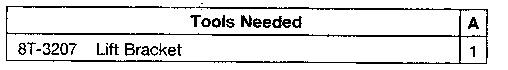
Start By:
a. separation of tracks
Shutdown SIS
D3C, D4C AND D5C SERIES III HYSTAT TRACK-TYPE TRACTOR POWER Media Number -SENR1251-03 Publication Date -01/11/2004
Date Updated -08/04/2013
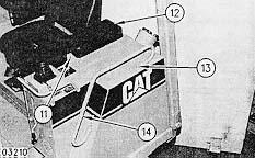
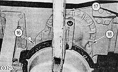
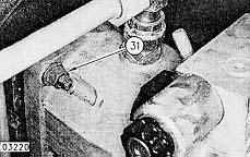
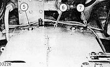
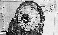
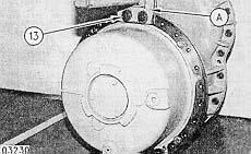
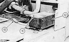
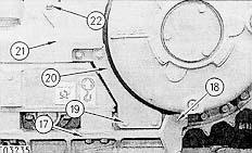
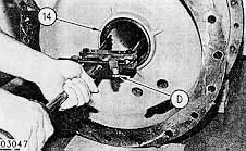
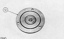
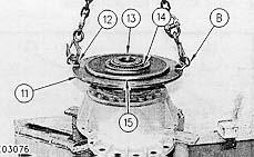
4. Remove two bolts (11) and cushion assembly (12). Remove two bolts (13) and handhold (14).
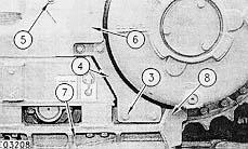

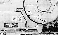
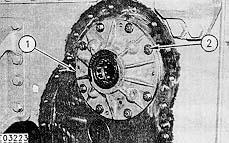
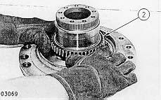
1. Remove plugs (1) and (2) and drain the fluid from the final drive. The capacity of the final drive is 20.5 L (5.5 gal U.S.).Install plugs (1) and (2) in the final drive.
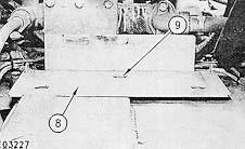
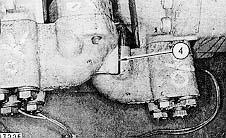
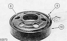
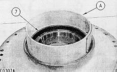
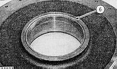
2. Remove three bolts (3), washers and guard (4). Remove three bolts (5), washers and guard (6). Remove four bolts (7), washers and guard (8).
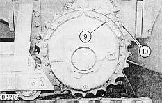
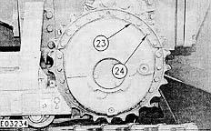
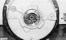
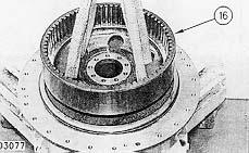
3. Remove twenty-five bolts (9) and five sprocket segments (10).
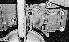
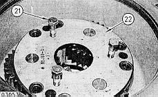
9. Remove eighteen bolts (21).
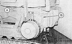
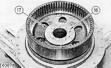
7. Remove three bolts (16), (17) and (18).
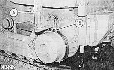
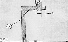
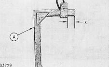
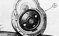
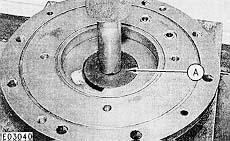
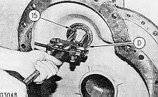
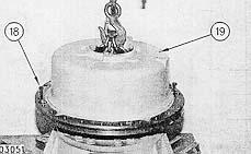
6. Attach Tooling (A) to a hoist and to the final drive assembly using two 1/21/4 - 20 X 2bolts (15) and washers.
5. Adjust the bracket on Tooling (A) until dimension (X) is 225 mm (9 in).
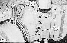
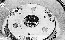
8. Install three M16 X 7.5 cmstuds (19) and two M16 X 50 mmpusher bolts (20).
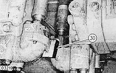
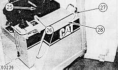
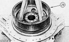
14. Install wood block (30) between the two drive motors as shown.
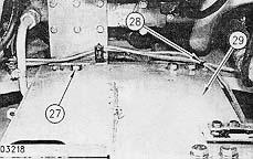
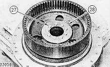
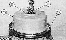
13. Cut strap (28) and remove eight bolts (27), washers and plate (29).
10. Turn pusher bolts (20) and remove the final drive assembly. The final drive assembly weight is 322 Kg (710 lb).
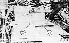
12. Remove three bolts (25), washers and plate (26).
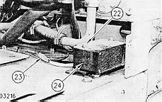
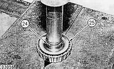
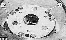
11. Remove two bolts (22) and washers. Disconnect wire connector (23) and remove back up alarm assembly (24).
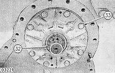
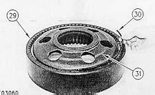
15. Remove four nuts (31) and washers.
Install Final Drive
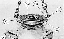
16. Remove gear assembly (32), eight bolts (33) and washers.
Care must be taken to ensure that fluids are contained during performance of inspection, maintenance, testing, adjusting and repair of the machine. Be prepared to collect the fluid with suitable containers before opening any compartment or disassembling any component containing fluids. Refer to "Tools And Shop Products Guide," NENG2500 for tools and supplies suitable to collect and contain fluids in Caterpillar machines. Dispose fluids according to local regulations and mandates.
Fluid Spillage Containment
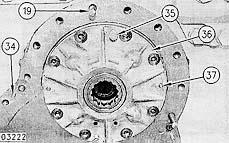
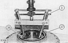
17. Install two M12 X 40 mmpusher bolts (35) and remove cage assembly (36). If necessary remove and replace two dowels (34) and two dowels (37).
4. Install plate (6), eight bolts (5), washers and strap (7).
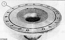
1. Install cage assembly (1), eight bolts (2) and washers. Apply 4C-9502 Sealantto the threads of bolts (2).

3. Remove wood block (4).
5. Install plate (8), three bolts (9) and washers.
2. Install four nuts (3) and washers.
6. Install back up alarm assembly (12), two bolts (11) and washers. Connect wire connector (10).
7. Adjust the bracket on Tooling (A) until dimension (X) is 225 mm (9 in).
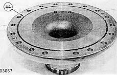
9. Clean surfaces (14) and (15). Apply a 3-4 mm wide bead of 6V-6640 sealantto the final drive assembly as shown.
8. Attach Tooling (A) to a hoist and to the final drive assembly using two 1/21/4 - 20 X 2bolts (13) and washers.
Install guard (18), four bolts (17) and washers. Install cover (21), three bolts (22) and washers. Install cover (20), three bolts (19) and washers.
14. Fill the final drive with oil to the correct level. The capacity of the final drive is 20.5 L (5.5 gal
NOTE:U.S.).
13. Install handhold (27) and two bolts (28). Install cushion assembly (25) and two bolts (26).
Refer to the topic "Lubricant Viscosities & Refill Capacities" in the D3, D4 and D5 TrackType Tractor Operation & Maintenance Manual SEBU7077 for the correct filling procedure.
NOTE: For D5C Track-Type Tractor, tighten bolts (24) to a torque of 240 ± 40 N*m (177 ± 30 lb 12.ft).
10. Install the final drive assembly on the machine. Install twenty-one bolts (16) and washers. Remove Tooling (A).
11. Install five sprocket segments (23) and twenty-five bolts (24) on the final drive assembly. Tighten bolts (24) to a torque of 120 ± 20 N*m (88 ± 15 lb ft).
b. connection of tracks
End By:
Start By:
Care must be taken to ensure that fluids are contained during performance of inspection, maintenance, testing, adjusting and repair of the machine. Be prepared to collect the fluid with suitable containers before opening any compartment or disassembling any component containing fluids. Refer to "Tools And Shop Products Guide," NENG2500 for tools and supplies suitable to collect and contain fluids in Caterpillar machines. Dispose fluids according to local regulations and mandates.
a. remove final drive
a. install batteries
Disassemble Final Drive
Fluid Spillage Containment
4. Repeat Step 3 for the opposite side of gear (7).
1. Remove four studs (1), two O-ring seals (2), O-ring seal (3) and O-ring seal (4) from the cage.
2. Using a press and Tooling (A), remove bearing (5) from the cage.

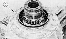
5. Remove gear assembly (8) from the final drive assembly.
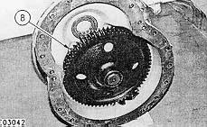
3. Using a press and Tooling (B), remove bearing (6) from gear (7).
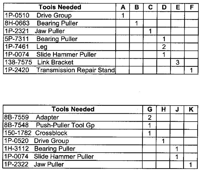
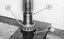
6. Using Tooling (A) and (C), remove bearing (9) from the gear.
9. Remove shaft (13) by pushing the shaft from the opposite side.
8. Remove O-ring seal (12).
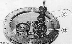
10. Using Tooling (D), remove race (14).
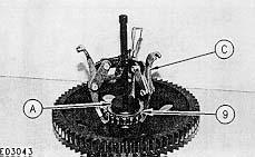
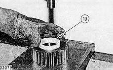
7. Remove three bolts (10), washers and cover (11).
11. Using Tooling (D), remove bearing (15).

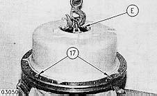
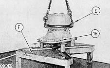
12. Using a suitable lifting device and Tooling (E), position the final drive assembly on Tooling (F). Install four M16 X 60 mmbolts (16), washers and nuts. Remove Tooling (E).
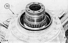
14. Install two M12 X 175 mmpusher bolts (18) and remove carrier assembly (19). The weight of the carrier assembly is 75 Kg (165 lb).
15. Remove six bolts (20) and washers from the carrier assembly.
13. Install Tooling (E) as shown using three M10 X 35 mmbolts and washers. Attach a suitable lifting device and remove four bolts (17).
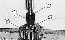
18. Using a suitable press, remove shaft assembly (24) from gear assembly (23).
16. Install three M16 X 60 mmpusher bolts (21) and remove plate (22).
19. Using a suitable press, removes shaft (24) from bearing (25).
22. Repeat Steps 17 thru 21 for the remaining two gear assemblies.
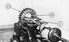
20. Using Tooling (D), remove cup (26) from gear (23).
21. Repeat Step 20 for the opposite side of gear (23).
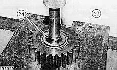
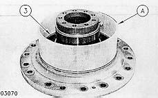
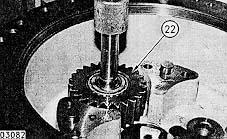
17. Using Tooling (D), remove gear assembly (23).
24. Using a suitable lifting device, remove gear assembly (29). The weight of the gear assembly is 27 Kg (60 lb).
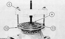
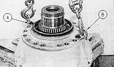
26. Install Tooling (G) and (H) as shown. Pull hub assembly (32) and bearing (33) from its seat.
23. Remove nine bolts (27) and retainer (28) from the final drive assembly.
25. Remove ring (30) and hub (31) from gear (30).
30. Repeat Step 28 for the opposite side.
29. Remove Duo-Cone seal (37).
33. Install Tooling (E) as shown using two M12 X 40 mmbolts (40). Attach a suitable lifting device and remove spindle assembly (41) from case (42). The weight of the spindle assembly is 43 Kg (95 lb).Remove Tooling (E).
28. Using Tooling (J), remove cup (36).
32. Remove Duo-Cone seal (39).
27. Remove bearing (33) and O-ring seal (35). Install Tooling (E) and two 1/2 X 1-1/2bolts (34), and washers. Using a suitable lifting device, remove hub assembly (32). The weight of the hub assembly is 64 Kg (140 lb).Remove Tooling (E).
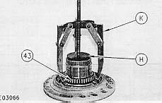
34. Using Tooling (H) and (K), remove bearing cone (34).
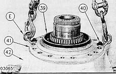
31. Remove eighteen bolts (38) and washers.
Fluid Spillage Containment
1. Install O-ring seal (1) on the spindle.
Care must be taken to ensure that fluids are contained during performance of inspection, maintenance, testing, adjusting and repair of the machine. Be prepared to collect the fluid with suitable containers before opening any compartment or disassembling any component containing fluids. Refer to "Tools And Shop Products Guide," NENG2500 for tools and supplies suitable to collect and contain fluids in Caterpillar machines. Dispose fluids according to local regulations and mandates.

Assemble Front Drive
NOTE: Removal may cause damage to the cone.
35. Turn the spindle over and remove O-ring seal (44).
NOTE: Refer to "Assembly And Installation Of Conventional Duo-Cone Seals" in this module.
3. Using Tooling (A), install Duo-Cone seal (3) in the spindle. Make sure the rubber torics and all surfaces contacting them are clean and dry at assembly. The seal ring must be assembled square with bore and rubber toric must not be bulged or twisted.
2. Heat bearing cone (2) to 120° C (248° F).Use temperature resistant gloves to install bearing cone (2) on the spindle as shown. Make sure the bearing cone is properly seated.
4. Install Tooling (B) as shown using two M12 X 40 mmbolts (4) and washers. Attach a suitable lifting device and position the spindle assembly on the case. The weight of the spindle assembly is 43 Kg (95 lb).Remove Tooling (B).
5. Install eighteen bolts (5) and washers.
Thank you very much for your reading. Please Click Here. Then Get COMPLETE IfNOTE:MANUAL.NOWAITINGthereisnoresponse to click on the link above, please download the PDF document first and then clickonit.

7. Repeat Step 6 for the opposite side.
11. Heat bearing cone (14) to 120° C (248° F).Use temperature resistant gloves to install bearing cone (2) on the spindle as shown.
NOTE: Refer to "Assembly And Installation Of Conventional Duo-Cone Seals" in this module.
6. Lower the temperature of cup (6) and install the cup in the hub.
8. Using Tooling (A), install Duo-Cone seal in the hub assembly. Make sure the rubber torics and all surfaces contacting them are clean and dry at assembly. The seal ring must be assembled square with the bore and rubber toric must not be bulged or twisted.
9. Install hub (8) and ring (9) in gear (10).
NOTE: While the bearing cone is still hot, proceed to Steps 12 and 13.
10. Install Tooling (B) on hub assembly (11) as shown using two 1/2 X 1-1/2bolts (12) and washers. Attach a suitable lifting device and position the hub assembly on spindle (13). The weight of the hub assembly is 64 Kg (140 lb).Remove Tooling (B) and install O-ring seal (15).
13. Install retainer (17) and nine bolts (18). Tighten the nine bolts (18) to a torque of 120 ± 20 N*m (88 ± 15 lb ft).
12. Install gear assembly (16) on the spindle
14. Lower the temperature of cup (19) and use temperature resistant gloves to install cup (19) in the gear as shown.
16. Heat bearing cone (20) to 120° C (248° F).Place bearing cone (20) as shown on Tooling (C). Using a press, install shaft (21) until it is seated against Tooling (C).
15. Repeat Step 14 for the opposite side.
21. Install Tooling (B) as shown using three M10 X 35 mmbolts (26) and washers. Attach a suitable lifting device and position carrier assembly (29) on the hub assembly. The weight of the carrier assembly is 75 Kg (165 lb).
19. Repeat Steps 14 thru 18 for the remaining two gear assemblies.
17. Place gear assembly (22) on the shaft assembly. Heat bearing cone (23) to 120° C (248° F).Using Tooling (C) and (D) and a press, install bearing cone (23).
18. Using a suitable press, install gear assembly (22) in the carrier assembly.
20. Install plate (25), six bolts (24) and washers. Tighten the bolts to a torque of 300 ± 70 N*m (221 ± 51 lb ft).
22. Install four bolts (27) and remove Tooling (B).