Academic and Professional Selected Works by CHIA-HSUAN(JOSHSUAN), CHAO
chiahsuanchao@icloud.com
Linkedin
Github
Chia-Hsuan, Chao (JosHsuan)
Born in 1994.07
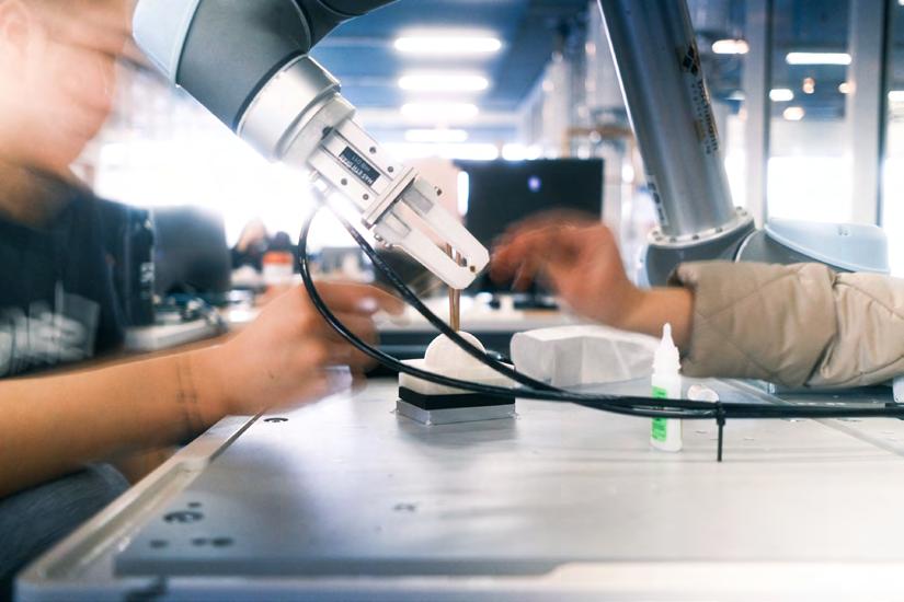
Joshsuan Chao is a computational designer, digital craftsman, and XR developer with 7 years experience specializing in digital design-to-fabrication practices within the architectural and industrial design fields. His work focuses on leveraging digital software and hardware, as well as XR and robotic arm applications, to advance design practices and realize innovative solutions.
EDUCATION
Federal Institute of Technology in Zurich(ETH Zürich), Switzerland
Master of Advanced Studies(MAS) in Architecture and Digital Fabrication |2023-2024
National Cheng Kung University (NCKU), Taiwan
Master of Architecture-Design, Computing and Digital Fabrication |2017-2020
Fu Jen Catholic University (FJU), Taiwan
Bachelor of Landscape Architecture |2012-2017
WORK EXPERIENCE
Research Assistant
Gramazio Kohler Research (GKR), Zürich, Switzerland
Keyskills:C#,Unity,MetaQuest,Rhino,Grasshopper,Github
*ServedasaVR/ARdeveloper
*ImplementedandresearchedvariousVR/MRtrackingmethodsforhumanbody&environment
*Implementedandresearchedthenetworkedmultiplayerframework
*ImplementedtheshadergraphmethodtorenderthematerialsinVRenvironment ResearchProject:EchoXR-Anapplicationforreal-timeacousticsimulationforarchitecturedesign
Computational Designer & BIM Engineer
PKD Engineering Consultants, Taipei, Taiwan
Keyskills:Python,Rhino,Grasshopper,AutoCAD
*Responsibleforgeometryoptimizationandrationalisationforcurtainwallsystem
*Communicatedwithstructuralengineeranddetailexpert
*Implementedthecurtainwalldesignschemesforconstructionfirm
*Implemented3Dmodellingand2Dfabricationdrawingforcurtainwallsystem
|TaiwanChinPaoSanNecropolis/StevenHall
|KaohsiungPortTerminal/Reiser+Umemoto
Facilities Technician (Part-Time)
|2024-Now
|2021-2022
|2018-2019 sKY_Associative Maker Space, Tainan, Taiwan
Keyskills:3DPrinter,LaserCutterMaintenance&Repairing
*Servedasfacilitiesmanagerforfabricationfacilities(LaserCutterand3DPrinter)
Architectural Designer (Contract)
UrbanWASABI Architect, Tainan, Taiwan |2017.07
Keyskills:Rhino,Grasshopper
ParticipatedinTainanLioujiaanimaleducationcenterandfielddesigncompetition
|Assistedindesigndevelopmentand3Dmodeling.(won2ndPrize)
THESIS
An Extended-Reality App Using Motion Capture for Bending-Active Structures |2024 Keyskills:C#,Python,Unity,Rhino,Grasshopper,OptiTrack,Firebase,MQTTIoTMessaging,Github
*Thisprojectproposesaworkflowthatincorporatesmotioncapturetechnologytointegratereal-worldinformation intotheprocess,enablingthereal-timegenerationofadaptivedigitalmodelsindesign-to-fabricationphase.
Bending-Active Metal Panel Deformation
- Control through Computational Simulation and Pattern Development |2020 Keyskills:Python,Rhino,Grasshopper,Designmethodology,Materialtesting
*TheresearchprovidesanewstrategyutilisingtheMiuraorigamipatterntorepresentthesurfaceflowofthe bending-activeplateandapproximatethebending-activeplatetotheproposedgeometrythroughlinearregression.
Reinterpretation of Refinery
- Turning Brownfield into Urban Habitat : A Case Study of Kaohsiung Refinery |2017 Keyskills:Rhino,Grasshopper,ArcGIS
*Theprojectexploresurban-scaledesignstrategies,focusingonurbandesignforthe"Brownfield"ofrefinerysites. Itemploysparametrictoolstosupportdesigndevelopmentandlarge-scalefactorymodeling.
HONORS & AWARDS
1st Prize, National Student Landscape Design Competition, Taiwan |2016.12 [Poster]
FLATaiwan&TaiwanInstituteofLandscapeArchitects outof501
1st Prize, National Landscape Architecture New Generation Award, |2017.05 [News]
IFLATaiwan&TaiwanInstituteofLandscapeArchitects outofallannualundergraduatestudents
OTHER EXPERIENCE
PUBLICATIONS
CAADRIA 2023
|2023.03 [Publication]
Bending-ActiveMetalPanelDeformation ControlThroughComputationalSimulationandPatternDevelopment Teaching
Tutor in CTAA Architect/ LAB, Tainan, Taiwan |2020.08 *tutoredsoftware(Rhino&Grasshopper)forInterns
Tutor in NCKU Summer Workshop, Tainan, Taiwan |2021.04 *tutoredsoftware(Rhino&Grasshopper)anddesignmethodfor10Students. Cooperation Project
Taiwan Engineering Talents Development Plan |2018.06-2018.11 InstituteforInformationIndustry,Taiwan|ChimeiModex|sKYassociate
Keyskills:Rhino,Grasshopper |Servedasadesignerforaproduct-grade3D-printedlamp,responsiblefortheprocessfromdesigntofabrication.
SKILLS
Languages
Chinese(Native),English(C1)
Programming
Python,C#,Processing
2D, 3D Modeling & Rendering & Fabricating
DesigndrawingwithRhino,Grasshopper,AutoCAD,Sketchup
GamedevelopmentwithUnity
ScenariorenderingwithVray,Keyshot,Lumion
Familiarwith3dPrinter、CNC、LaserCutRoboticFabricationandGcodeseriestooltodigitalfabricating
Graphic Design, Layout and Video Editing
ProficientinAdobeSuitePhotoshop,Illustrator,Indesign,Premiere,AfterEffects andworkseamlesslybetweeneditingandLayout
PORTFOLIO
[Link to portfolio]
An Extended-Reality App Using Motion Capture for Bending-Active Structure
ETH MAS DFab T3 Thesis
Keywords: Compas XR, Motion Capture, Bending-Active, Weaving, Mola
Tutors: Alexandra Moisi, Prof.
Daniela Mitterberger
Location: Zurich, Switzerland
Institution: MAS DFab, ETH Zurich
Date: 2024
Collaboration: Wataru Nomura
In recent years, the field of digital fabrication sometimes has employed extended reality technologies to project pre-designed digital data of structures onto devices such as mobile phones, head mounted displays, and smart glasses.
This study proposes a workflow that incorporates motion capture technology to integrate real-world information into the process, enabling the real-time generation of adaptive digital models in design-to-fabrication phase. By doing so, we introduce flexibility into the extended reality assembly process, allowing the digital model to adjust based on the physical environment.
Additionally, we examined how to improve the user experience for assemblers by utilizing real-time visualization of material posture via motion capture technology, tracking the deformation of natural materials (bamboo in this case), and optimizing the application’s user interface to make our app more intuitive. A demonstration using a modularized bending-active bamboo structure allowed for the real-time editing of parameters.
Ultimately, this approach aims to provide assemblers with more intuitive guidance, helping them navigate complex processes and making the assembly of bendingactive structures more adaptable and efficient.
Fig.1-01 The mobile application of thesis project
The design workflow is a combination between bottom-up approach "Form Finding" and top-down approach "Form-Conversion". The set up process begins with plane recognition (A) to establish a reference frame. Then, control points can be repositioned (B) to adjust the foundation and Y-shape intersections. Finally, the digital model’s length and radius (C) are modified. Steps B and C interact dynamically but follow A. This hierarchical sequence ensures precise adaptation to site conditions.
The design workflow utilizes a physics engine to define adaptive form-finding processes. Control parameters are embedded in a mobile application for real-time on-site adjustments. Once the final shape is determined, it is modularized into Y-shaped units. A mesh grouping strategy is then applied to convert the mesh into a strip-weaving pattern using the Form-Conversion approach.
Fig.1-04
Fig.1-03 The mobile based application of the Interactive Form Adaptation System
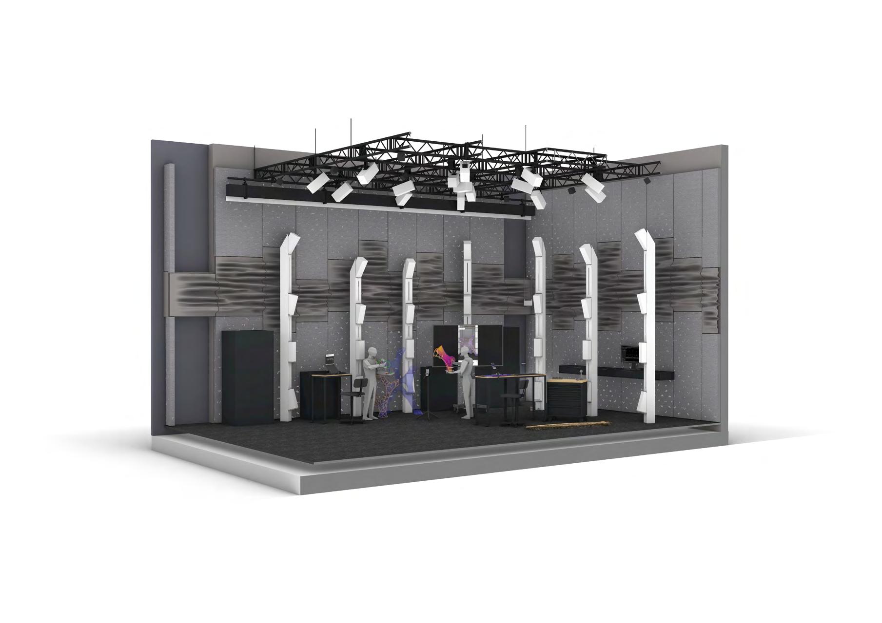
The hardware architecture integrates QR code markers and motion capture cameras for spatial localization and tracking. CAD software calculates adaptive models, displaying results on a television by casting mobile phone screen. The mobile application develops in our project facilitates real-time design configuration and module visualization. Workers use phones to send commands, ensuring precise module assembly. This system enables adaptive design visualization, optimizing real-time guidance and structural accuracy during fabrication.
The module assembly process involves attaching passive markers to the bottom rod, selecting the module number, and marking each current rod. A mobile application provides real-time tracking and guidance, while a display visualizes assembly progress, ensuring precise alignment and integration of components.
Fig.1-05 The Integrated Adaptive Design-to -Assembly System
The software architecture enhances the COMPAS XR framework by integrating adaptive functionality for real-time adaptability, cross-platform data delivery, and model storage. It utilizes MQTT for high-frequency motion data transmission and Firebase for cloud storage, ensuring smooth CAD-to-XR visualization. Worker decisions are sent back via MQTT, with Firebase preserving task progress during interruptions. This
system improves workflow coordination, adaptability, and digital fabrication efficiency by addressing the lack of adaptive model storage in previous research. The integration of MQTT topics enhances control over the design-to-fabrication process, offering a more flexible and responsive approach to XR-assisted digital workflows.
The equipments of mobile-based XR application in utilizing the OptiTrack camera system and three types of dynamic tracking markers. These markers define planes, spatial positioning points, and circular extrusion radii, enabling precise motion tracking and seamless integration between digital and physical workflows for enhanced real-time adaptability.
Fig.1-08 The Motion Tracking and Adaptive Assembly Environment
Fig.1-07 Software Architecture : The Cloud-Based Motion Capture and XR Integration System
Fig.1-09 The Workflow of Real-Time Data Serialization and Deserialization
The data delivery workflow focuses on cross-platform data integration by categorizing data into real-time, assembly, and configuration types. Data is serialized into JSON for cloud storage and deserialized for use in Rhino (Python) and Unity (C#). Geometric structures like Mesh and Curve are converted into numerical data (vertices, faces, colors) for seamless
adaptation. Configuration data ensures consistent adaptive parameters, allowing workers to preview and interact with the design in real time. This framework facilitates efficient data transmission, real-time adaptability, and synchronization of worker decisions between CAD and XR platforms, enhancing the digital fabrication workflow.
Fig.1-10 The MQTT-Based Real-Time Data Communication Framework
Regarding MQTT data communication, this study utilizes EMQX as the broker. By creating different topics, the CAD platform and the app can subscribe to and transmit data, facilitating communication between the two. The workflow's topics can be categorized into three main types: real-time data from motion capture, trigger data from the app interface buttons, and worker requests.
Fig.1-16 The Manual Assembly of Parametric Bamboo Structure
Fig.1-15 The Augmented Reality-Assisted Fabrication Process
Fig.1-14 The Real-Time Motion Capture and Collaborative Design Interaction
Fig.1-12 The Interactive Motion Capture and Augmented Reality Design Process
Fig.1-11 The Motion Capture MarkerTracking
Fig.1-13 The Precision Fabrication Process with Motion Tracking
Fig.1-19 The Completed Demostration
Fig.1-20 The Completed Demostration
Fig.1-17 The Completed Demostration and Design Team
Fig.1-18 The Modular Parametric Bamboo Components for Assembly
PROJECT_CASCHLATCH
ETH MAS DFab T2 Project
Keywords: Compas XR, Compas Timber, Complexity, Caschlatch
Tutors: Ananya
Kango, Simon Griffioen, Petrus Aejmelaeus-Lindström
Location: Zurich, Switzerland
Institution: MAS DFab, ETH Zurich
Date: 2024
Collaboration: ETH MAS DFab 2324
The project "Project Caschlatch," is a coorperation project in Gramazio Kohler Research, ETH Zurich using COMPAS XR and COMPAS Timber. The workflow integrates CAD data, serialized and uploaded to a cloud server, with AR applications for real-time module management.
Furthermore, the project based on multi-module assembly, enhanced by a voxel-based aggregation system, ensuring structured growth and precise beam intersection. This method rationalizes beam distribution, prevents redundant intersections, and ensures structural integrity throughout the assembly process.
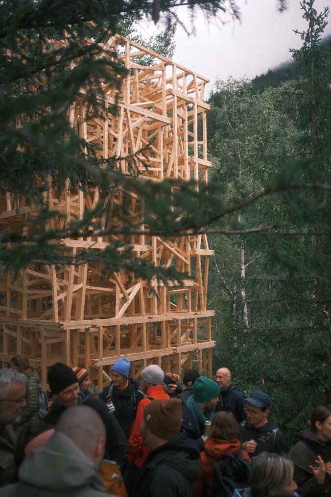
Fig.2-01 The Architectural Model of a Timber Tower
Fig.2-02 The Construction of a Timber Structure
The Computational Design Framework for Voxel-Based Structural Generation
The design logic developed using Python and Grasshopper for beam aggregation. It consists of five classes: ID and Discrete Vector Generator for processing, and Voxel, Beam, and Layer for geometric representation. The ID class manages voxel indexing and neighborhood relations, while Discrete Vector Generator provides random vector calculations. Voxel handles spatial discretization, Beam defines structural elements, and Layer organizes voxel groups.
The design logic for converting voxels into beams is using a 26-directional discretization method, beams are rationally aggregated to ensure each beam intersects at the cube's center point. Stored voxel data tracks existing beams, ensuring that each beam intersects only with another at a single point and prevents redundant intersections. Overall, the transformation is from voxel-based spatial mapping to beam-based aggregation, ensuring a controlled and efficient aggregation process for modular construction systems.
Fig.2-04 The Voxel-to-Beam Transformation Process for Modular Construction Systems
Fig.2-03
The voxel-based system ensuring structural functionality and visual coherence in beam aggregation. The design logic incorporates initial module frames with supporting beams along the edges for stability. Modules are further reinforced with orthogonal and diagonal support elements to enhance structural integrity. Different levels of beam infill (5-beam, 30-beam) are applied based on functional equirements.
In the end, we built an 8.4-meter-high tower serving as a landmark near Disentis village, inviting hikers to rest near historical ruins. The structure integrates a modular beam aggregation system, ensuring stability and aesthetic harmony with the surrounding landscape. Offering visitors a place of break and breath while preserving the site's cultural and historical significance.
Fig.2-05 The Voxel-Based Modular System with Structural Infill Strategies
Fig.2-06 The Voxel-Based Parametric Tower Integrated with Site Topography
In the production period, I responable for enhanced the COMPAS XR system feature, made the application allowing users to manage multi-module assembly tasks by selecting and switching modules from a cloud server, tracking beam IDs, and following the assembly sequence in real-time. Next, the functionality of the stacking AR application used for managing assembly modules. It allows users to orient beams, float and scale modules, switch modules from the cloud, and toggle between stacking and assembly modes, providing detailed information and control over the assembly process.
Fig.2-07 The XR-Guided Robotic Fabrication and Assembly Workflow
Fig.2-08 The Augmented Reality-Based Beam and Module Assembly System
The AR assembly workflow where CAD data is serialized into JSON and OBJ formats, uploaded to a Firebase cloud server, and then deserialized for use in an AR application. Users interact with the AR application, and their data can be serialized and sent back to the cloud, facilitating seamless data exchange and visualization. The data format workflow for managing and exporting building data using COMPAS TIMBER and COMPAS XR applications. The process begins with the creation of an assembly plan in COMPAS TIMBER, which is then


exported as JSON files for building plans and checklists, and as OBJ files for mesh data. These files are uploaded to a cloudbased server using Firebase, where they are stored in a realtime database. The data can then be accessed and visualized through the COMPAS XR application, enabling users to interact with and manage the building project efficiently. This workflow facilitates seamless data transfer between the design and execution phases, ensuring accurate project implementation.
The user interfaces of two developed apps designed for the project incorporate key features such as beam orientation display, floating and scaling functions, and module rotation for precise alignment. Users can switch between stacking and assembly modes, fetch modules from a cloud server, and view sequence order for structured assembly. Additionally, an info panel provides details on selected beams, while real-time interactions enhance visualization and selection.
Fig.2-10 The XR Interface for Modular Assembly and Beam Positioning
Fig.2-09 The Cloud-Based Data Exchange Framework for XR and CAD Integration
Fig.2-15 The Collaborative Timber Structure Assembly Process
Fig.2-16 The Robotic-Assisted Timber Module Assembly
Fig.2-14 The XR-Guided Timber Assembly Process in a Collaborative Workshop
Fig.2-11 The Timber Tower Model with Site Topography
Fig.2-12 The Timber Tower Model with Site Topography (Front View)
Fig.2-13 The Timber Tower Model with Site TopographyModel
Fig.2-17 The partial of the Timber Structure
Fig.2-18 The interior of the Timber Structure
Fig.2-20 The modules assembly by helicopter
Fig.2-21 The Final Assembly of Timber Tower on Site
Fig.2-19 The interior stair of the Timber Structure
BENDING-ACTIVE METAL PANEL DEFORMATION
Control thru. Computational Simulation and Pattern Development
Keywords: Bending Active, Material System, Digital Fabrication, Computational Simulation, Miura Folding
Description: Individual Thesis
Tutors: Prof. Kane Yanagawa
Location: Tainan, Taiwan
Institution: National Cheng Kung University
Date: 2020
The bending-active system is one of efficient and responsible use of materials to reduce the impact on the environment and provide a more sustainable future for humanity. To apply the bending-active system to architecture practices, formfinding and form-conversion are the existing strategies of the bending-active system and have unique characteristics respectively.
In this research, we provide a new strategy to integrate the advantages of existing strategies utilising the Miura origami pattern to represent the surface flow of the bending-active plate and approximate the bending-active plate to the proposed geometry through linear regression.
The result demonstrates this new bending-active strategy has a high potential to apply to a lightweight and efficient structure. Moreover, the workflow using the Miura origami as the bending-active representation shows a new branch of the bending-active plate system, origami patterns-based bending-active strategies.
Regardingtheworkflow,theresearch introducedanewbending-activedesign strategythatintegratesthecharacteristics ofform-finding(bottom-up)andformconversion(top-down)techniques Startingwiththesampleddata,abending simulationofpattern-basedopeningswas usedtopredictthechangeinoverallplate bending.
Toconverttheopeningandthebending angle,weestablishedthemathematical functionlibrarybybendingtestingthe resultoflinearregression.Therefore,the openingvaluesandthebendingangles couldbebi-directionaltransferredthrough thisfunctionlibrary.
Workflow of pattern-based strategy in
While the Miura folding is adapting to the purpose surface, the elasticity of the model had been extracted and the representation of the folding model could remain the rigid crease. Then, we could get the value of each local folding angle, which could be used to transfer into the opening through the function library. Following this, we add a new vertex on each mesh face and contribute the new relationship with each initial
mesh vertex to create a new mesh edge and mesh face. After that, we must add the proper pairs of vertices on the opening edge again to set up the coincidence of opening in the dynamic physical simulation. In the last stage, we subdivided the mesh into proper densities and add the elasticity back to the model to simulate the sewing opening.
Fig.3-03
bending-active system
Fig.3-04 Form Approximation based on origami pattern
To efficiently convert the folding representation into the bending-active model, we adopt linear regression to build the math function to represent the data library. This data library consists of three parameters, such as opening length, width, and deformation angle. First of all, we set up a pair of patterns to simulate the deformation and extract the endpoints to build the folding representation for measuring the folding angle.
Starting with the fixed opening length of 60mm and the width stepped increased by 1mm from 0mm to 50mm. Moreover, we use linear regression to convert these data into a math linear function with two variables. Next, based on using this method, the length gradually stepped increased by 10mm from 70mm to 160mm and created a three-dimension math function created by this series of linear functions.
Fig.3-05 Transformation function library
Fig.3-06 Method of angle measuring
Fig.3-07 The database of transformation function library
Thetypicalsurfacemock-upsrevealtheperformanceof thestrategy.First,whileperformingthearcsurface,the peakangle,andwidthvalueofthebendingdeformation werelargethanthevalleyvalue.Moreover,eachpair opening,perpendiculartothebendingdirection, showsthesamevalue.Then,whileperformingthe twistbehaviour,thepairsofpeakandvalleyvalueshad oppositerelationships.Third,thesaddlebehaviour demonstratesthetrendsofperformingthetypicalarc intheparalleldirection.Furthermore,thevaluesof boththepeakandvalleyhavedecreasedtrendsfrom thecentreoutwardintheperpendiculardirection.
Fig.3-09 The parameter of typical surface (fixed length)
Fig.3-10
The parameter of typical surface (width & length)
First of all, we installed a spatial installation (3.3m * 2.6m * 0.7m) utilising the bending active method of the panel assembly, and the geometry of this installation demonstrates the performance of arc, twist, and saddle
Furthermore, in comparison to the more common surface deformation methods, the strategy of our research only required cut patterns to control the surface curvature as well as control the border of the panels by the designer to greatly reduce material waste, instead of the typical form conversion strategy generates the unpredictable border of panels.
While assembling the panels, three pairs of holes were located at the extension of the fixed distance from the border of each opening and locked with the fixed-size plastic band and the rivet.
Fig.3-11 The detail of opening sewing
Fig.3-12 Final prototype
Fig.3-13 The detail of panel joint
Due to the maintenance of panel elasticity, 16 panels (90cm * 60cm each) rely on a bag (60cm * 35cm * 35cm) hung in a motorcycle (see figure 5) and merely required one-hundredth of capacity to transport the materials. Moreover, the whole process of assembling merely spend three days with two workers.
This result shows the bending-active plate system of this research allows for convenient transportation and repeatable assembly as well. Accordingly, the advantages are suitable for architectural applications requiring high degrees of flexibility and lightweight construction.
Fig.3-14 The process of panel sewing
Fig.3-15 Final prototype
MODE/S OF MAKING
Heat Rotate Cutting
Keywords: Mass Customization, Digital Craftsmanship, Digital Fabrication, Computational Simulation
Description: Studio Project
Tutors: Prof. Kane Yanagawa
Location: Tainan, Taiwan
Institution: National Cheng Kung University
Date: 2018
Collaboration: Jan Kyselý(Photo)
Over the past 2.5 million years, humanity has continued to advance new tools at an ever-accelerating rate from the abacus, to the slide rule, calculator, and computer. Although these innovations are typically made to address specific problems, each new tool correspondingly opens doors to numerous unforeseen opportunities.
The project explores the use of machines as the designer's design tool, using open source frame Arduino as well as Marlin to integrate the design and fabrication. Moreover, the designer started from the study of the fabrication mechanism and respond to the design process, using Arduino to control the cutting path, speed, and other variables.
In sum, the research uses emergent digital technologies to bridge the gap between designers and manufacturing which coincidently brings interesting results.
The material system adopts polystyrene bricks as the main material and heat rotation cuts to every single brick to practice mass customization. To directly fabricate the customized bricks, we build a mass-customized frame with data format transformation and machine-customized fabrication. Overall, it can be seen that the procedure from design to fabrication consists of five stages. The process has five stages,
Fig.4-02 The workflow from design to fabrication
beginning with geometry development. Then it will undergo the cutting path optimization and the data format be converted into Gcode, which is used to read by the machine. Meanwhile, the machine set by Arduino was remodelled from a 3D printer open-source frame- Marlin. Finally, ends up with the assembly process through referencing the simulation model.
The hardware system was built with aluminium and the customized units were built with 3D printing. The machine was designed by the core XY system and was controlled by two stepper motors. When stepper motors have the same direction, the motion of the mechanism has a vertical direction. On the contrary, when stepper motors have the opposite direction, the motion of the mechanism has a horizontal direction.
Fig.4-03 The framework of fabricating machine
Next, the rotation mechanism relies on a stepper motor controlling the speed and direction of rotation. The opposite has a holder, which is adaptive to hold various sizes of material. Lastly, the Endstop was used to adjust the cutting position.
Thevariouscircularsurfacebrickswerefabricatedbyrotating cuttingpaths.Eachcustombrickwasdesignedtoconnect withotherssmoothlyandtaggedwiththelocationnumber. Moreover,singlebricksspentabout10-15minutesfor fabricating.Whileassemblingthebricks,8brickunitscanbe assembledintobiggerunitsandsoon,whichcontributetothe skeletonpatternswithdifferentsizesofinternalsanddensities.
Themachinehastwomainmechanismssystem, therotatingmovementsystem(Y)andtheplane movementsystem(XZ).Theplanemovementsystem controlsthetoolpathofthesection,andtherotating movementsystemcontrolsthesectionposition.
/01stepmotor
/02motorholder
/03smoothmetalrods
/04belt
/05synchronouswheel
/06idlerwheel
/07bearing
/08aluminumrod
/09soldering
/10balljoint
Fig.4-06 Fabricating process
Fig.4-07 Fabricating process
Photo by Jan Kyselý
Fig.4-08 The detail of the machine
The fabrication process consists of two main steps, roughing and milling. At this point, the prototype aimed to integrate the potential of rotated cutting, the polystyrene blocks were cut by the different depths of the path and arranged to assemble in a specific position. While the roughing period, each tool path was parallel and have a higher forward-moving of depth to decrease the fabricating time consumption. Then, the milling period was one slower movement with a continuous path to make sure the final face is smooth.

Instead of general design to fabricate workflow, studying and inspiring from the fabricating tool have a high potential to bring serendipity. At the first, the design expected to cut the form such as the skeleton pattern and control the gap variety with the round thickness of the skeleton. After the roughing step and removing the most of material, the machine started to mill according to the tool path and accidentally revealed the unique pattern generated from the tool path.
Fig.4-12 Real model prototype
Fig.4-13 Real model prototype
Fig.4-09 Real model prototype
Photo by Jan Kyselý
Fig.4-10 Real model prototype
Photo by Jan Kyselý
Fig.4-11 Real model prototype
ENTRANCE INSTALLATION ART
Taichung Nan Shan no.6 Square
Keywords: Mass Customization, Fabrication Drawings, Complex Modelling, Computational Simulation
Description: Work Project
Employer: Peter Chen
Location: Taichung, Taiwan
Institution: PKD Engineering Consultants
Date: 2021
Collaboration: Zhi-Yu Guo(2D Sector), Monita(Structural Sector)
The entrance installation art project of the Taichung Nan Shan no.6 square is entrusted by Fu Tsu Construction and is a public art of the master building. The project was developed by three people team for three months and is currently on exhibit. This chapter records the parts of scheme development, 3D modelling and fabricating drawings, in which I played a key role in the project.
The installation was assembled with 600 aluminium folding panels with various openings, which were fabricated by a traditional aluminium factory. The assembly process is merely by human hands. In sum, the key point of this project is the bi-directional transformation of 3D models and 2D drawings and delivering the drawing to hand fabricating.
The geometry of the installation art started with a simple NURBS surface. Then, subdividing the triangle size depends on considering the manufacturing limitation such as the fabricating scope. Following this, adding the depth from the control of the triangle panel in order to create the pattern. The last, using the helix curve to evaluate the distance with every central point of the panels and making the openings on every panel with the list of distances.
While developing the pattern of the panels, we provided various schemes to the client. In terms of the size of the opening on the panels, the minimum radius of the triangle inscribed circle is large than 8cm in order to provide enough space for repairing the light facility. Regarding the minimum height of the opening panel, it is necessary to be higher than 200 meters to make sure the security of the children. In sum, all of the pattern schemes are satisfied the above requirements.
Fig.5-03 The pattern development
Fig.5-02 The pattern development
Fig.5-04 The schemes of pattern
The assembly system has two types, including two ears panels and three ears panels. The panels were hung by the module hanger. Moreover, every ear of the folding panel has a customized shape to cooperate with the fixed depth of the component. Every two panels were a pair with fixed holes in the middle and the upper ear and lower ear of each panel had pairs of alignment holes.
Fig.5-09 The fabricating drawings of panels
In order to deliver the fabricating drawings to the local traditional factory, we integrate each folding angle and every manual checking data into the drawings. Meanwhile, depends on laser cutting, to transform the digital data into real folding panels. All in all, the construction could rely on the machine fabricating and the checking data to make sure every panel is successfully fabricated.
Fig.5-05 The section of the installation art
Fig.5-06 The panel assembly of two joints
Fig.5-08 Two joints panel
Fig.5-07 Three joints panel
Fig.3-05 The panel assembly of three joints
(assembly on site)
(assembly on site)
(assembly on site)
(assembly on site)
(assembly on site)
(assembly on site)
(assembly on site)
(assembly on site)
FR515. Hex Bolts (M5 x 15mm)
FR520. Hex Bolts (M5 x 20mm)
FR615. Hex Bolts (M6 x 15mm)
FK510. Round Head Machine Screw (M5 x 10mm)
FG4813. Round Head Self-Drill Screw (M4.8 x 13mm)
FG4819. Round Head Self-Drill Screw (M4.8 x 19mm)
ST02. Steel Plate (2mm)
-Hot Dipped Galvanized
ST05. Steel Plate (5mm)
-Hot Dipped Galvanized
ST09. Steel Plate (9mm)
-Hot Dipped Galvanized
ST12. Steel Plate (12mm)
-Hot Dipped Galvanized
ST5050. Steel Square Tube (50 x 50 x 3t)
-Hot Dipped Galvanized
ST1032. Steel Square Tube (100 x 100 x 3.2t)
-Hot Dipped Galvanized
ST1045. Steel Square Tube (100 x 100 x 4.5t)
-Hot Dipped Galvanized
ST106. Steel Square Tube (100 x 100 x 6t)
-Hot Dipped Galvanized
SS753. Steel Folded Plate (75 x 75 x 3t)
SS7545. Steel Folded Plate (75 x 75 x 4.5t)
SS01. Stainless Steel Plate (1.5mm)
SS381. Stainless Steel Pipe (1.5” 3mm)
EX01. Alloy 6105-T5 (L=30mm)
L01. LED Strip (L=100~500mm)
L02. LED Strip Aluminum Channel Holder (L=15mm)
Fig.5-10 Module A of steel structure - perspective
Fig.5-11 Module B of steel structure - perspective
Fig.5-12 Module C of steel structure - perspective
(reference only)
(EX01 drilling Ø4.5, SS01 drilling Ø5.5)
(drilling Ø6.5) plug weld (two screws for length < 500mm; three screws for length > 500mm)
(reference only)
reference only
reference only
(EX01 drilling Ø4.5, SS01 drilling Ø5.5)
(drilling Ø6.5) plug weld (two screws for length < 500mm; three screws for length > 500mm)
drilling Ø5.5) oval slot Ø6.5 x 10 oval slot Ø6.5 x 10
(central point of assembly seam)
Bridging detail drawing of the vertical section
(central point of assembly seam)
Overall, there are three layers of systems including the panel system, the steel pipes system, and the structure system. The steel pipes system was used to locate the panels; each pipe had a different radius. Moreover, the pipes were accurately located by the beam and column system which was built with steel tubes. Since module A had a large radius of the pipe system and the panel system, the steel tube system add the bracings to satisfy the structure needed.
Fig.5-14 Detail drawing of the vertical section
Regarding the reference standard, it is necessary to establish a fixed reference surface. In the detailed drawing, we can see every component was located referencing the central curve of the pipe. Furthermore, every central curve of the pipe was generated from the intersection of a reference surface and the height of the pipes in order to efficiently located the various module components which have complicated relationships with the reference surface.
(EX01 drilling Ø4.5, SS01 drilling Ø4)
(EX01 drilling Ø4.5, SS01 drilling Ø4)
central curve of the pipe
central curve of the pipe
(EX01 drilling Ø5.5)
(EX01
Fig.5-13
The installation art was almost 8 meters in height and was located near the Taichung city train station, a high-frequency traffic commercial district. Following this point, photos reveal how to divide the installation into three modules and fabricate them. Every module was no need for scaffolding to aid fabricating. The modules were preassembly and pre-sprayed in the factory before transporting them to the real site in order to decrease the time consumption of assembly on the real site and satisfy the transporting size of the truck and the width of the roads.
Fig.5-15 The photo of detail
Fig.5-16 The photo of structure (inside)
Fig.5-17 The photo of module A
Fig.5-18 The photo of module B
Fig.5-19 The photo of module C
Fig.5-20 The photo of panel detail
Fig.5-21 The photo of panel detail
Fig.5-23 The photo in real site
Fig.5-24 The photo in real site
Fig.5-22 The photo in real site
SPECIAL ASSEMBLIES
V-Shape Modular Based Aggregation
Keywords: Reciprocal Aggregation, COMPAS Assembly , Trajectories Optimization, RTDE Control, ROS
Description: Term 1 Project
Tutors: Ananya Kango, Simon Griffioen, Petrus Aejmelaeus-Lindström
Location: Zurich, Switzerland
Institution: MAS DFab, ETH Zurich
Date: 2023
Collaboration: Kevin Seav, Megi Sinani
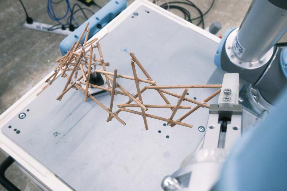
V-shape modular-based aggregation project inspired by the reciprocal structure, using the prototype assembled by sticks to demonstrate the design workflow of implementing the path optimization for collision-free trajectories by the robotic arm.
In this project, we use the bottom-up strategy to generate the V-shape module aggregating the sticks which follows the reciprocal structure. During the study, we observed the aggregating behaviours and summarized them into four categories. Finally, integrates into the OOP programming methodology to generate the aggregation.
define class: -Stick -V Stick Module
generate aggregation
The workflow for planning and executing robot trajectories using ROS (Robot Operating System) and Docker. The process begins with defining classes (Stick and V Stick Module), then generating an aggregation. The trajectory is planned using ROS and MoveIt, and the data is exported as JSON. Simulations can be run, and if necessary, the trajectory is replanned. Finally, the planned trajectory is sent to the robot for execution.
replan trajectory send to robot plan trajectory
JSON Based Data Delivery
generate Assembly()
assembly.part
assembly.attributes -shape -frame -axis -safe frame -num parts
plan_motion
pick_trajectory
place_trajectory
exit_trajectory
insert_trajectory
fail_index
series of frames approach frame to pick frame
series of frames approach frame to safe frame
series of frames safe frame to approach frame
series of frames safe frame to place frame
generate Trajectory
The Software Architecture of the Sticks Aggregation
replan_motion_by _index
pick_trajectory
place_trajectory
exit_trajectory
insert_trajectory
series of frames approach frame to pick frame
series of frames approach frame to safe frame
series of frames safe frame to approach frame
series of frames safe frame to place frame
The JSON-Based Robotic Assembly Planning Process
The data format in the workflow is JSON-based data delivered for robot motion planning. It begins with generating an assembly, which includes parts and attributes. The plan_motion function then defines various trajectories (pick, place, exit, insert), each involving a series of frames. If a failure occurs, the motion can be replanned by index. The final step involves generating and exporting the trajectory, potentially with a replan index, all delivered in JSON format for execution. This process ensures structured and flexible robotic motion planning and execution.
Fig.6-04
Fig.6-05
The VStickModule class has two main methods:
The create_VStick_module method creates a V-shaped module. It performs geometric operations to create two Stick objects and returns an instance of VStickModule.
The next_VStick_module method generates the next module based on the previous V-shaped module and certain parameters. It creates new Stick objects based on geometric calculations and returns a new instance of VStickModule.
The 'toggle' parameter directs the creation of module elements. Set as "NW" or "SW," it generates sticks via geometric operations, impacting their alignment. When 'toggle' is "NE" or "SE," similar operations with adjusted references produce an
updated set of sticks. This parameter crucially guides geometric actions, defining orientations and relationships among the newly formed module sticks.
Fig.6-06 The Algorithm of V-Stick Modules Aggregation
Fig.6-07 The Process of V-Stick Module Assembly and Directional Aggregation
INSERT trajectory
series of frames safe frame to place frame
PLACE trajectory
series of frames approach frame to safe frame
EXIT trajectory
series of frames safe frame to approach frame
PICK trajectory
series of frames approach frame to pick frame
INSERT trajectory
PLACE trajectory
EXIT trajectory
PICK trajectory
Check collision
Sort by Z in module
Check frame Zaxis
Regarding TCP correcting, the plane of every stick is defined by the X-axis and Z-axis. The Z-axis represents the grippe's direction. When the Z-axis of the plane faces up, the gripper might cause a collision with the working table.
Chosen configuration (fine_tune_params)
Sorted by Z Fixed frame Zaxis
Therefore, we create a function correcting the plane's Z-axis. The function is based on referring to the Z value of the Z-axis vector. If the value is higher than Zero, which means the vector is facing up, then we flip the plane.
Fig.6-09 The Structural Optimization Process for Collision-Free Assembly
Fig.6-08 The Robotic Assembly Trajectory for V-Stick Aggregation
Fig.6-10 The Set Up Process of the Sticks Aggregation Foundation
Fig.6-12 The process of assembly
Fig.6-13 The process of assembly
Fig.6-11 The Robotic Assembly Process for Small-Scale Prototyping
Fig.6-15 The process of assembly (Top View)
Fig.6-16 The process of assembly (Front View)
Fig.6-17 The process of assembly
Fig.6-14 The process of assembly
PRINTING ARCHITECTURE
Dot-Based Non-Planar 3D Printing
Keywords: 3D Printing, Non-Planar, Dot-Based Print Path
Description: Term 1 Project
Tutors: Ananya Kango, Simon Griffioen, Petrus Aejmelaeus-Lindström
Location: Zurich, Switzerland
Institution: MAS DFab, ETH Zurich
Date: 2023
Collaboration: Namdev Talluru
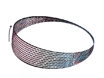
This project explores the application of dot-based and non-planar 3D printing techniques to create complex architectural forms. The study initially investigates how variations in printing parameters, such as layer height, density, and velocity control, affect the microscale patterns and surface textures of printed objects. The project then extends these findings to larger, more intricate shapes, analyzing how the established printing rules adapt to different geometries. The outcome is a series of detailed, textured objects that showcase the flexibility and potential of dotted-based 3D printing methods. .
The prototype of different parameters Set up
Fig.7-01
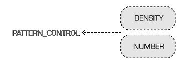
The project initially explored a series of 3D-printed objects created through controlled variations in printing parameters. The diagram on the left details the key factors influencing the printed patterns, including the number of slices (layer height and density), pattern control (number and textile length), pattern change (delay height and velocity), and velocity control (v_ step).
The formula explains how the number of frames in each slice is determined based on the density and the slice length. These parameters collectively affect the final printed pattern's detail and complexity.
IF LAYER HEIGHT DELAY HEIGHT: DO SMOOTH CURVE ELSE: DO DOTTED
The Delay Height parameter in 3D printing controls surface texture: when set, it creates smooth curves; when unset, it produces a dotted, segmented pattern, enabling varied tactile and visual effects.
Final Results of the Workshop
Fig.4-01
Photo by Chia-Hsuan, Chao
Fig.7-03 The Pattern Effects of Different Parameters Set Up
Fig.7-04
The microscale patterns is affected by adjusting the robotic arm's path and applying time delays in 3D printing. Through precise control of path configurations and delay settings, varied and intricate surface textures are created, showcasing the detailed impact of these adjustments on the printed object's final appearance.
The last is through the adaptation of 3D printing rules to various shapes to examine how the printing patterns perform when applied to more complex and varied overall forms, showcasing the flexibility and limitations of these patterns in different geometries.
Fig.4-02 Physical Model
Photo by Chia-Hsuan, Chao
Fig.7-06 The Geometry Development Based on Dot-Based Non-Planar 3D Printing
Fig.7-05 The Different Strategies for Dot-Based Non-Planar 3D Printing
Fig.7-12 The Demostration of Dot-Based Non-Planar 3D Printing (With TEPG)
Fig.7-09 The Demostration & Prototypes
Fig.7-08 The Prototype of Dot-Based Non-Planar 3D Printing
Fig.7-07 The Demostration of Dot-Based Non-Planar 3D Printing (With TPU)
Fig.7-10 The process of 3D printing
Fig.7-11 The process of 3D printing
Fig.7-13 The Prototypes of Dot-Based Non-Planar 3D Printing (Geometry Development)
Fig.7-14 The Demostration & Prototypes (TPU)
INSIDE OUT
IDF 2019 Workshop
Keywords: Minimal Surface, Form Finding, Weighted-Mesh, Differential Tiling
Description: Workshop
Tutors: Prof. Chung-Han, Lee
Location: Yunlin, Taiwan
Institution: Idea Factory, National Yunlin University of Science and Technology
Date: 2019
Collaboration: Individual work Kenta Saito(Cooperation Prototype Assembly) Group work IDF2019 Workshop participants
Inside Out is a workshop individual result of the IDF 2019 workshop. This 5-days workshop focused on the use of differential tiling on complex geometry. Moreover, the workshop explored both the techniques for the design and the behind theories of mesh analysis methods.
The workshop covered instruction in Grasshopper, Kangaroo and Ivy to introduce the design workflow of the mesh. In addition, the workshop has two phases, two days for two people teamwork and three days for whole group work. The chapter extracted the small teamwork result that I was responsible for and demonstrated the process of the final prototype.
Fig.8-01 Final Results of the Workshop
Photo by Chia-Hsuan, Chao
Fig.8-02 Physical Model
Photo by Chia-Hsuan, Chao
First of all, the initial geometry is a mathematical geometry called the Split P Surface. Then, the longest border of the geometry was selected to limit movable on the plane while the Form-Finding phase. Meanwhile, every mesh edge was configured to grow 1.2 times in length and used the laplacian smooth method to smooth the mesh.
The
In terms of the differential complex geometry mesh, we use different algorithms and add some custom weight in order to make the segmentation following the targets, the minimum number of panels and the lowest curvature changes on each panel. Moreover, it is necessary to insure each segmentation is smaller than the size of the laser cut machine.
The workflow of weighted-mesh differential segmentation
Fig.8-03
unrolling of differential panel tiling
Fig.8-04
Stare at the Silence
Keywords: Mesh Subdivision, Mola , Radii, Complexity
Description: Term 1 Project
Tutors
: Ananya Kango, Simon Griffioen, Petrus Aejmelaeus-Lindström
Location: Zurich, Switzerland
Institution: MAS DFab, ETH Zurich
Date: 2023
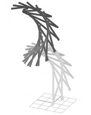
This project, titled "Mesh Subdivision: Stare at the Silence," is an exploration of advanced geometric patterns and spatial complexity through the technique of Mesh Subdivision. Building upon the foundational work of Prof. Benjamin Dillenburger and leveraging the Mola library, this project delves into algorithmic design and computational fabrication. The intricate structure showcased in the image is a result of subdividing a mesh into smaller, more detailed components, creating a visually complex and mathematically rich form. Through iterative processes and precise algorithmic manipulation, the design embodies a delicate balance between form and function, emphasizing both the aesthetic beauty and the underlying mathematical rigour of Mesh Subdivision.
GENERATIVE
ART
Planet of Colorful Garden
Keywords: Harold Cohen, Rhino.Geometry , GHPython, Randomness
Description: Term 1 Project
Tutors: Ananya Kango, Simon Griffioen, Petrus Aejmelaeus-Lindström
Location: Zurich, Switzerland
Institution: MAS DFab, ETH Zurich
Date: 2023
This project, titled "Generative Art: Planet of Colorful Garden," is inspired by the artwork of Harold Cohen, combining algorithmic techniques and computational tools to create intricate, nature-inspired visuals. The artwork is a digital representation of a vibrant, organic world. The project leverages tools like Rhino. Geometry and GH Python to generate randomness, simulating natural elements such as trees, branches, and leaves on complex 3D geometries. The visual output reflects a fusion of structured geometry and random transformations, resulting in a dynamic and colorful representation of a garden-like planet.
ELEMENTS
Tree( ) branch( ) plant_Spiral( ) mushroom( ) big_leaves( )
Random_Mesh_Ball( ) stone( ) mist( )
LOCATION ON 3D GEOMETRY
Pt_on_Surface( )
Pt_on_Mesh( )
Line & Curve Mesh Nurbs Surface
VAULE PROCESSING
Tremble( ) RANDOM TRANSFROM
Tiny_move_random( ) moveXY_random( ) moveXYZ_random( ) Jitter_colour( ) remap( )
Description: Industry Cooperation project
Location: Taiwan
Institution: NCKU X CHIMEI | MODEX
Date: 2018
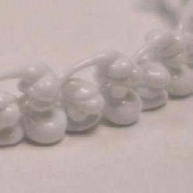
Description: Individual works
Location: Taiwan
Date: 2021
The Puff Waffle is an individual study inspired by Andrew Kudless 's P wall. Trying to demonstrate the shape of the squeezed liquid. Beginning with using the hexagon as the panel and making them tiling on the sphere. Then, generated the differential growth curve on each panel and let them be the restricted paths on the panels. Finally, inflating each hexagon panel.
Enter the Void is a collaboration with the leading 3D filament brand CHIMEI | MODEX to promote the utilisation of 3D printing technology. The result was required to demonstrate the advantages of the 3D printing technique. The design is based on the mathematical form called GYROID. then, morphed on hyperbolic paraboloid to generate the complex geometry. Moreover, to consider the disassembly method of the complex geometry and the fabricating requirements.
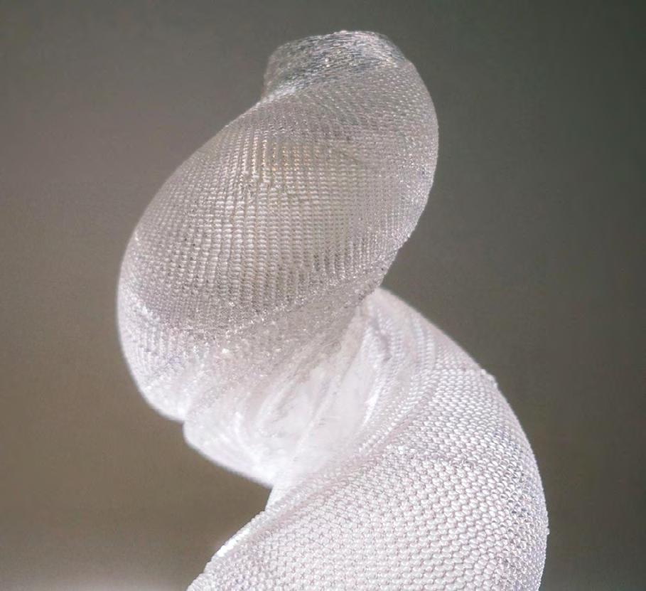
The EggShell is the individual creative work to explore the extremely thin 3D printing product. One of the interesting patterns was generated by the agents. First, the agents were arranged at the bottom and restricted on the surface. Then, gave them the force of movement and recorded it.
Finally, the printing path was designed as a continuous curve to achieve no seam profile and directly generate G-code by grasshopper to control the various parameters such as movement speed and extrusion quantity.
Description: Individual works
Location: Taiwan
Date: 2020
Description: Workshop by Digital Future
Tutors: Maria Yablonina, Samuel Ledar
Location: Shanghai, China
Institution: CAUP Tongji University and Stuttgart ITECH
Date: 2019
Collaboration: Group Stuttgart ITECH
F5 is a project led by Stuttgart ITECH in a week-long workshop. The project explored the trend of collective robotic construction through the use of bespoke mobile machines to create adaptable spaces.
In the project, the participants were involved in the assembly, choreography, and installation stages of a bespoke robot system. Moreover exploring the choreography of the machine movements as it relates to physical space and human interaction.