5 minute read
Passive Lighting System & Active Lighting System


Passive lighting system –Window
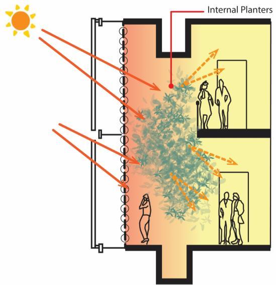
Glare Control
Advertisement
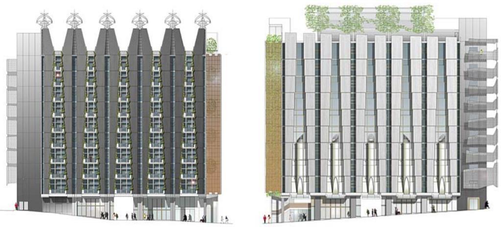
External plants: each of the windows on the northern facade has a balcony with trellised planting on each side. Internal plants: moveable internal planters on each side of most windows on the south elevation
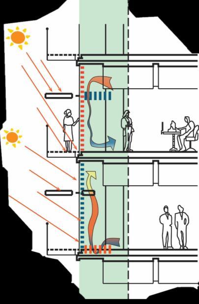
Wide to Narrow
The lower level receives lesser light therefore windows closer to the streets are wider to maximize light and becomes narrower to the top to minimize glare

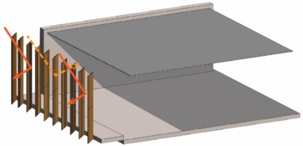
Active lighting system – Building Management System (BMS) Timber Louvres
The west facing façade is covered with a system of timber louvres that pivot to optimize the penetration of natural light protect the façade from the harsh western sun.

Lighting
The use of T5 light fittings for ambient lighting and individual task lighting for workstations will consume 65% less energy Fully Closed


Partially Open
Winter Mode
Energy Systems
During winter mornings, heated water pipes are required to heat the offices to ensure a workable office environment
Water Initiatives
Water collection stored in the basement to be used for heating pipes
Summer Mode
Shading Landscape
Timber shading provide Full summer shading while allowing filtered daylight Planted green roof tops to plantroom
Energy Systems Landscape
High level ceiling exhaust ensures complete emptying of warm air in ceiling spaces Protect inner façade from direct sunlight and fresh air naturally ventilates the toilet
HEATING SYSTEM
• Times throughout the year when CH2 does not need supplementary heating or cooling to maintain thermal comfort. Air entering the building through floor vents, usually at a
temperature of around 20 degrees, provides a basic ambient temperature control.
• Hot water will go through an underfloor hydronic system located around the perimeter windows. Given that air supplied to CH2’s office spaces is already heated to about 20°C, when heat is required, it is designed to be supplied at the points where heat loss is concentrated – the windows. • Hot water pipes are located in the underfloor space along the north and south walls, while beneath each window in the floor is a timber grille supplying radiant heat from the hydronic system. There are also small wall-mounted radiators along the south wall to
assist with heat to areas restricted by full-height partitions.
• The heat from the grilles under the forms a warm air barrier around the perimeters, which rises into the space naturally using buoyancy Cooling mode
COOLING SYSTEM
Council house 2 deal with heat load by rechilling recirculated air. The air is refreshed twice an hour, removing around 40 per cent of the heat load from the building. Remaining 60 per cent of the heat load is stored during the day and removed at night.
CHILLED BEAMS
• The chilled beams consist of copper tubes looped through a metal structure. The tubes tie into chilled water supply and return lines running in the cavities behind the precast concrete panels. • In passive mode, fresh air is supplied from the floor only. ( top picture ) • In active mode, the chilled beams operate and cool down the air supplied from the floor. (bottom picture )
Passive Mode Day Mode

Night Purge Indoor Environment Quality
Turbines
Wind driven cowls will generate electricity during the day
Chilled Panels and Beams
Occupants experiencing ‘coolth’ by radiating heat to chilled overhead ceilings
Water Initiatives
Phase change is done through the water plant. Water is piped to plant for re-cooling
Turbines
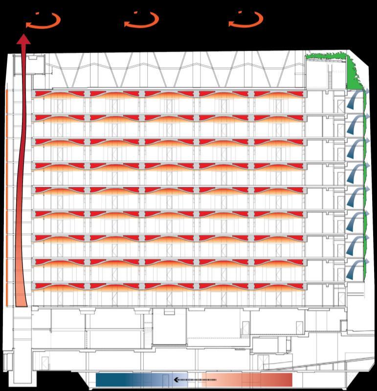
Assist purge ventilation by drawing air from individual floors through north ducts

Active Mode Thermal Mass

Heat build up in the concrete ceiling during the day is removed by the cold night air
Energy System
Roof top energy includes photovoltaic cells, solar hot water panels and gas-fired co-generation plant
Includes vertical ducts, Floor vents and exhaust
Shower Towers
The falling water cools the water for building reticulation. The cool air also supplements cool air for ground floor and retail
Window
During the night, the windows will automatically open. Cool air enters to cool the internal spaces
6 micro turbines
SOLAR ENERGY ( PHOTOVOLTAIC CELLS )

23 solar panels, which are equivalent to about 26 square meters of photovoltaic cells. These are located on the roof and generate close to 3.5kW of electricity from the sun’s energy.
23 solar panels
This amount of energy are responsible to power the movement of the western timber shutters. About 60 per cent of the building’s domestic hot water supply is provided by 48 square meters of solar hot water panels on the roof. The pie chart shows systems that uses solar power.

WIND TURBINE ( MICRO – TURBINE : CO – GENERATION )

The main function of the turbine ventilator is to remove heat from the vaulted ceiling and at the same time generate electricity . This happen when the inner fan spinning around the rotor and the rotor is connected to the main shaft which spins the generator to create electricity . This provides the building 60kVA of electricity, meeting up to 30 per cent of the building’s needs.

INDOOR ENVIRONMENT QUALITY
• Vertical ducts brings in 100% of outside air to be supplied to each floor to sealed access floor plenum • Fresh air fed at low speed for air displacement through controllable floor vents • The exhaust located in each floor ceiling ensure complete emptying of warm air in ceiling • Wind turbine induced air flow out into the outdoors.


