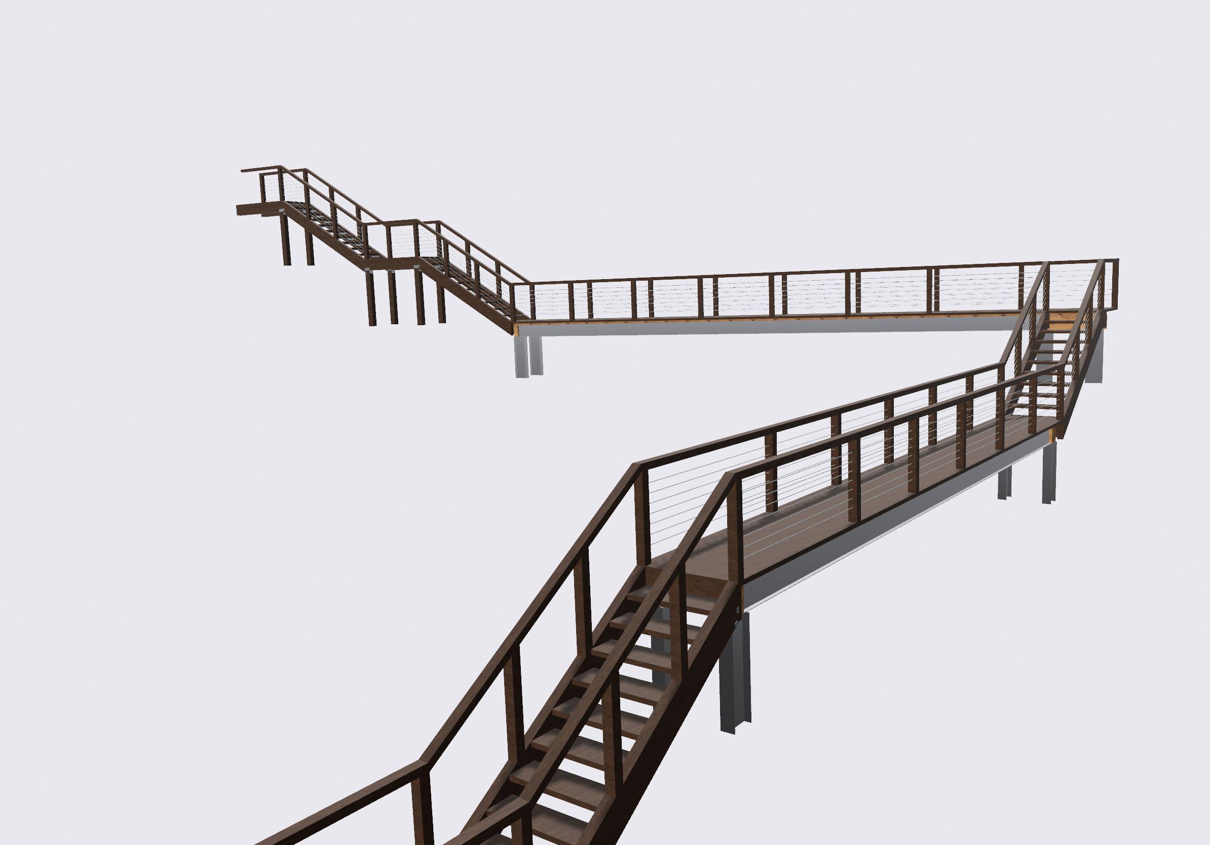
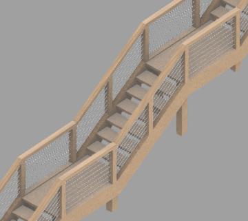
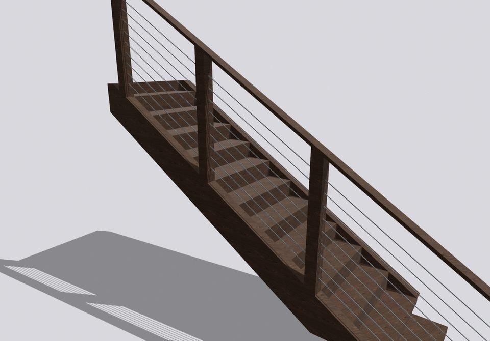
Stair Calculations
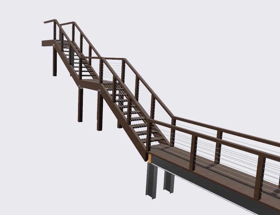

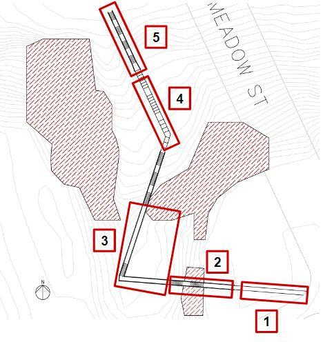
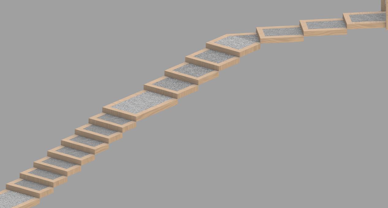
The following pages are preliminary calculations for the stair. This calculation only focuses on the stairs in the top of the project, since these are larger and contain longer columns. Therefore, these set of stairs will face larger forces and are more likely to fail. Since the team is planning to use the same material dimensions for both set of stairs (top and bottom), we believe that if we make sure that the top stair sets are found to be sufficiently strong, the bottom stairs will be acceptable as well. Each of the seven staircases in the top of the system have the same design except for the column lengths. This means treads and stringers only need to be analyzed once. The column are also analyzed in these calculations, the team chose to calculate the staircase with the longest column, since these will face the largest forces.
Calculations will be based on -National Design Specification for Wood Construction (2018) by the American Wood Council -NDS Supplemental (2018)
-ASCE 7 (2022)
-AASHTO Signs (2015) -International Building Code (2021) -Manual for Engineered Wood Construction (2018)
- DCA 6 -Prescriptive Residential Wood Deck Construction Guide (2015) by the American Wood Council
CalculateCapacityofTreads,makesuredimensions chosenareappropriate Non-Commercial Use Only
Stair Groups Stair Calculation CEA R:GAH 12/05/2022 1 of 28
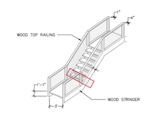
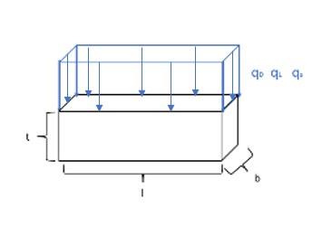
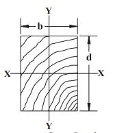
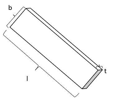
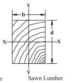
Stair Groups Stair Calculation CEA R:GAH 12/05/2022 2 of 28 CalculateCapacityofTreads,makesuredimensions chosenareappropriate Treads 2inx12in Based on DCA 6 Standard Dressed Dimensions: ≔ tt 1.5 in height NDS Supplement (Table 1B) ≔ bt 11.25 in width NDS Supplement (Table 1B) ≔ lt 3 ft length The thread is in red Zoomed In thread with loads SectionProperties: Assuming that the wood can be considered Decking, since intended for floor use and wide face in contact with supporting members. Property Source ≔ Syy 4.219 in3 Section Modulus NDS Supplement (Table 1B) ≔ Iyy 3.164 in4 Moment of Inertia NDS Supplement (Table 1B) ≔E 1400000 psi Modulus of Elasticity Southern Pine No. 2 NDS Supplement (Table 4B) ≔ Fb 750 psi Bending design Southern Pine No. 2 NDS Supplement (Table 4B) ≔ Fv 175 psi Shear Parallel Southern Pine No. 2 NDS Supplement (Table 4B) ≔A 16.88 in2 Area of Section NDS Supplement (Table 1B) ≔G .55 Specific Gravity Southern Pine No. 2 NDS Supplement (Table 4B) ≔ ρw 62.4 lb ft3 Density water ≔ pb = ⋅ ⋅ ρw ⎛ ⎜ ⎝ G ( (1+ ⋅G ( (0.009 .19))) ) ⎞ ⎟ ⎠ ⎛ ⎜ ⎝ 1+ .19 100 ⎞ ⎟ ⎠ 34.353 lb ft3 Density of Southern Pine (NDS Supplement 3.13) Loads Non-Commercial Use Only
Ct 1.2 Thermal Factor ASCE 7, Table 7-3
C
I
.9 Terrain B, exposure factor ASCE 7-2
1 Importance Factor ASCE 7, Table 1.5-2
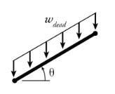
wD = 4.102 lbf ft 0.004 kip ft Dead, based on density of wood (NDS Supplement-Table 1B) pb
T = + wL wD 0.098 kip ft Total Applicable factored load governs with their respective time factor, λ Case Factored Load (ASCE 7, 2.3) λ (NDS 2018, Table N3) 1
wu1 = 1.4⋅wD 0.006 kip ft
λ1 .6 2 ≔ wu2 = + + 1.2⋅wD 1.6⋅wL 0.5⋅ws 0.164 kip ft ≔ λ2 .8 3 ≔ wu3 = + + 1.2⋅wD 1.6⋅ws wL 0.127 kip ft ≔ λ3 .8 ReductionFactors used in this analysis. All from NDS, 2018 Factor Name Source Reasoning
Ci 1 Incising Factor 4.3.8 There are no incisions
CF 1 Size Factor 4.3.6 lumber does not exceed 12" wide and it is not 4" thick
CL 1 Beam Stability Factor 3.3.3 Depth does not exceed breadth (d<b), in flatwise loading
b = bt 0.938 ft
d = tt 1.5 in
Temperature Factor 4.3.4 The structure will not experience sustained exposure of temps above 150F Non-Commercial Use Only
Stair Groups
CEA R:GAH 12/05/2022 3 of 28
≔
≔
≔
≔
≔
s
⋅ ⋅ ⋅
≔
≔
≔
≔
≔ Ct
Stair Calculation
Loads Given Loads: Name Source ≔ qL 100 psf Live weight (IBC Section 1604.3) Find snow load
qg 25 psf snow load ground ASCE 7-16
e
s
q
=
0.7⋅Ce Ct Is qg 0.131 psi snow load on surface ASCE 7.3-1 Find distributed loads
wL = ⋅ qL bt 0.094 kip ft Live
ws = ⋅ qs bt 0.018 kip ft Snow
w
≔
≔
≔
≔
≔
≔
≔
1
Stair Groups Stair Calculation CEA R:GAH 12/05/2022 4 of 28 ≔d = tt
≔ Ct
≔ CMb
≔
≔
r
≔
fu
Flexure Assume that the threads are Bending Members, since they will be primarly in flexure Calculate Adjusted Moment Capacity (M') ≔ M'⎛ ⎝Fb '⎞ ⎠ ⋅ Fb ' Syy (M3.3-2) Equation for Adjusted bending
Fb', given
load combinations
≔ Fb '( (λ) ) ⋅ ⋅ ⋅ ⋅ ⋅ ⋅ ⋅ ⋅ ⋅ ⋅ ⋅ Fb Ci CF CL Ci Ct CMb Cr Cfu 2.54 λ .85
≔ Fb1
≔
'
≔
≔
≔
≔
≔
⋅
u
≔
≔
≔
Non-Commercial Use Only
1.5 in
1 Temperature Factor 4.3.4 The structure will not experience sustained exposure of temps above 150F
0.85 Wet Service Factor, bending Sup. 4B Since stairs outdoor, moisture will exceed 19% for extended periods of time
CMv 0.97 Wet Service Factor, shear Sup. 4B
C
1 Repetitive Member Factor Sup. 4B treads are not in contact
C
1.2 Flat Use Factor Sup. 4B lumber is used flatwise, load applied to wide face
design
different
(NDS, 2018 Table N3)
(Table M4.3-1)
' = Fb '⎛ ⎝λ1⎞ ⎠ 990.981 psi
Fb2
= Fb '⎛ ⎝λ2⎞ ⎠ ⎛ ⎝1.321⋅103 ⎞ ⎠ psi
Fb3 ' = Fb '⎛ ⎝λ3⎞ ⎠ ⎛ ⎝1.321⋅103 ⎞ ⎠ psi Now can calculate M'
M1 ' = M'⎛ ⎝Fb1 '⎞ ⎠ 0.348 ⋅kip ft
M2 ' = M'⎛ ⎝Fb2 '⎞ ⎠ 0.465 ⋅kip ft
M3 ' = M'⎛ ⎝Fb3 '⎞ ⎠ 0.465 ⋅kip ft Calculate Factored bending moment for the three load combinations (Factored max moment, assume simple beam)
Mu⎛ ⎝wu⎞ ⎠
w
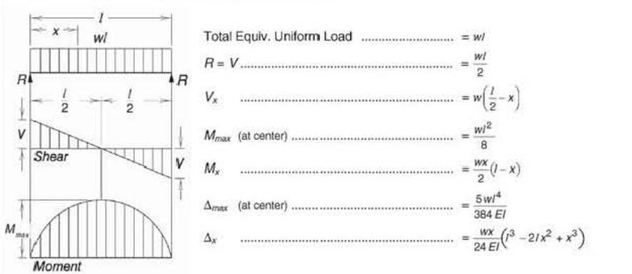
lt 2 8 (AISC Table 3-23- Aid 1)
Mu1 = Mu⎛ ⎝wu1⎞ ⎠ 0.006 ⋅kip ft
Mu2 = Mu⎛ ⎝wu2⎞ ⎠ 0.184 ⋅kip ft
Mu3 = Mu⎛ ⎝wu3⎞ ⎠ 0.143 ⋅kip ft Since M'>Mu for all three cases, it is acceptable (M3.3-1)
Checkslendernessratio RB Effective length (Table 3.3.3)
Shear
Stair Groups Stair Calculation CEA R:GAH 12/05/2022 5 of 28
≔
le = + 1.63⋅lt 3⋅d 5.265 ft ≔ RB = ⎛ ⎜ ⎝ ⎛ ⎝ ⋅ le d⎞ ⎠ b2 ⎞ ⎟ ⎠ 1 2 0.865 Less than 50, so acceptable
≔
⋅ ⋅
≔ Fv
⋅ ⋅ ⋅ ⋅ ⋅ ⋅ Fv
Mv
t
≔ F
=
v '⎛ ⎝λ
≔
≔
≔ V
≔
≔
≔ Vu⎛ ⎝wu⎞ ⎠ ⋅ wu
≔ Vu1 =
u⎛ ⎝wu1
≔ Vu2 = Vu⎛ ⎝wu2⎞
≔ Vu3 =
u
⎝
u3
Non-Commercial Use Only
Calculate Adjusted Shear Capacity, V'
V'⎛ ⎝Fv '⎞ ⎠
2 3 Fv ' A (M3.4-3) Calculate Adjusted shear design Fv' for given load combinations
'( (λ) )
C
C
Ci 2.7 .8 λ (Table M4.3-1)
v1 '
F
1⎞ ⎠ 219.996 psi
Fv2 ' = Fv '⎛ ⎝λ2⎞ ⎠ 293.328 psi
Fv3 ' = Fv '⎛ ⎝λ3⎞ ⎠ 293.328 psi Calculate V'
1 ' = V'⎛ ⎝Fv1 '⎞ ⎠ 2.476 kip
V2 ' = V'⎛ ⎝Fv2 '⎞ ⎠ 3.301 kip
V3 ' = V'⎛ ⎝Fv3 '⎞ ⎠ 3.301 kip Calculate factored bending moment for the three load combinations
lt 2 (Assume simple beam, AISC Table 3-23- Aid 1)
V
⎞ ⎠ 0.009 kip
⎠ 0.246 kip
V
⎛
w
⎞ ⎠ 0.191 kip Since V'>Vu for all three scenarions this is acceptable (M3.4-1)
Deflection
Deflection limits (Source IBC Table 1604.3) Deflection Midspan- uniformely loaded
Live Load = lt 240 0.15 in ≔ ΔL = ⎛ ⎝ ⋅ 5⋅wL lt 4 ⎞ ⎠ ⋅ 384⋅E Iyy 0.039 in (M3.5-1)
Total Load = lt 360 0.1 in ≔ ΔT = ⎛ ⎝ ⋅ 5⋅wT lt 4 ⎞ ⎠ ⋅ 384⋅E Iyy 0.04 in
Sincethelimits arelargerthanthedeflections,this is acceptable
CalculateCapacityofStringer,makesuredimensions chosenareappropriate Non-Commercial Use Only
Stair Groups Stair
CEA R:GAH 12/05/2022 6 of 28
Calculation
CalculateCapacityofStringer,makesuredimensions chosenareappropriate
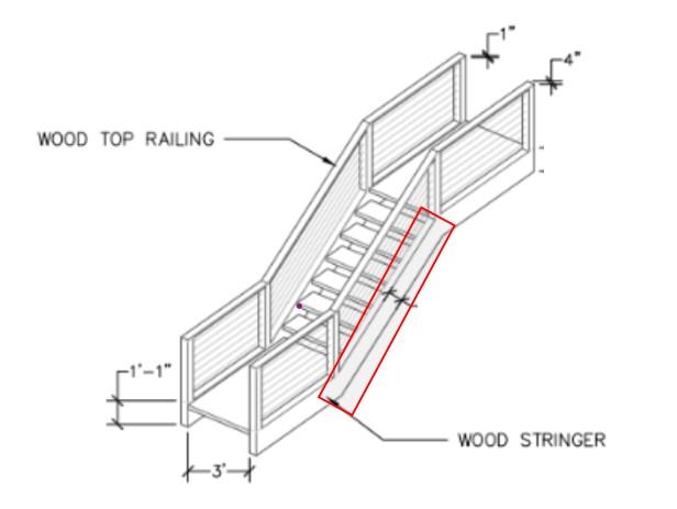
Stringer 4inX12in
Standard Dressed Dimensions:
s 3.5 in NDS Supplement (Table 1B)
bs 11.25 in NDS Supplement (Table 1B)
ls 11 ft (estimate, based on preliminary drawings) *Dimensions were first checked with minimum in DCA 6, however, this had too low of a slenderness ratio. Thickness was change to 4 in nominal
The stringer is in red Dimensions of Stringer
Section Properties:
Assuming that the wood is loaded on the narrow face and is dense select structural Property Source
Sxx 73.83 in3 Section Modulus (strong axis) NDS Supplement (Table 1B)
Syy 22.97 in3 Section Modulus (weak axis) NDS Supplement (Table 1B)
Ixx 415.3 in4 Moment of Inertia (strong axis) NDS Supplement (Table 1B)
Iyy 40.20 in4 Moment of Inertia (weak axis) NDS Supplement (Table 1B)
Modulus of Elasticity
Emin 690000 psi Min. Modulus of Elasticity
Comp parallel to grain
Fb 1800 psi Bending design
Southern Pine Dense Select Structural NDS Supplement (Table 4B)
Southern Pine Dense Select Structural NDS Supplement (Table 4B)
Southern Pine Dense Select Structural NDS Supplement (Table 4B)
Southern Pine Dense Select Structural NDS Supplement (Table 4B)
A 39.38 in2 Area of Section NDS Supplement (Table 1B)
Specific Gravity
Southern Pine Dense Select Structural NDS Supplement (Table 4B)
Stair Groups
CEA R:GAH 12/05/2022 7 of 28
Stair Calculation
≔ t
≔
≔
≔
≔
≔
≔
≔E 1600000 psi
≔
≔ Fc 1750 psi
≔
≔
≔SG .55
Non-Commercial Use Only
Stair Calculation
w 62.4 lb ft3 Density water = pb 34.353 lb ft3 Density of Southern Pine (NDS Supplement 3.13)
Loads Refer to tread loads, for live and snow load.
Dead Load Need to account for weight of treads and weigth of stringer. Since there are 12 treads, the density of the stringers and treads is the same, and each stringer will carry the weight of half of a tread, the total dead weight will be For a density of the approximate weight is 35 lb ft3
wDt 9.570 lbf ft (NDS Supplement-Table 1B) Assume each stringer carries half the weight of the treads
wD = +
⎛ ⎜ ⎝ ⋅ ⋅ wDt 12 lt 2 ⎞ ⎟ ⎠ ls wDt 0.025 kip ft
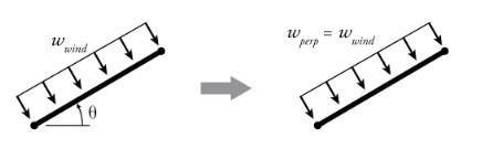
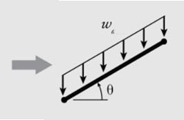
Wind Load An additional wind load is also included in calculation. Variables needed to find design wind pressure
Variable Name Source Reasoning
V 100 mph 300-Year MRI Basic Wind Speed AASHTO Signs, 3.8-3b Used map
Kz 1 Height and Exposure Factor AASHTO Signs, 3.8,4-1 Height less than 33 feet
Kd .85 Directionality Factor AASHTO Signs, 3.8,5-1 Assume support type is overhead frame/truss, this is also the lowest factor
G 1.14 Gust Effect Facotor AASHTO Signs, 3.8.6 this is the minimum number
Cd 2.0 Drag Coeffciient AASHTO Signs, 3.8.7 Assume two member or trusses
Wind pressure Equation :Pz
0.00256 Kz Kd G V2 Cd psf mph2 49.613 psf (AASHTO Signs, 3.8.1-1) The wind load will be a force both in the weak and strong axis of the stringer Non-Commercial Use Only
Pz = ⋅
Stair Groups
CEA
12/05/2022 8 of 28
R:GAH
≔ ρ
≔
≔
≔
≔
≔
≔
≔
≔
⋅ ⋅ ⋅ ⋅
The wind load will be a force both in the weak and strong axis of the stringer
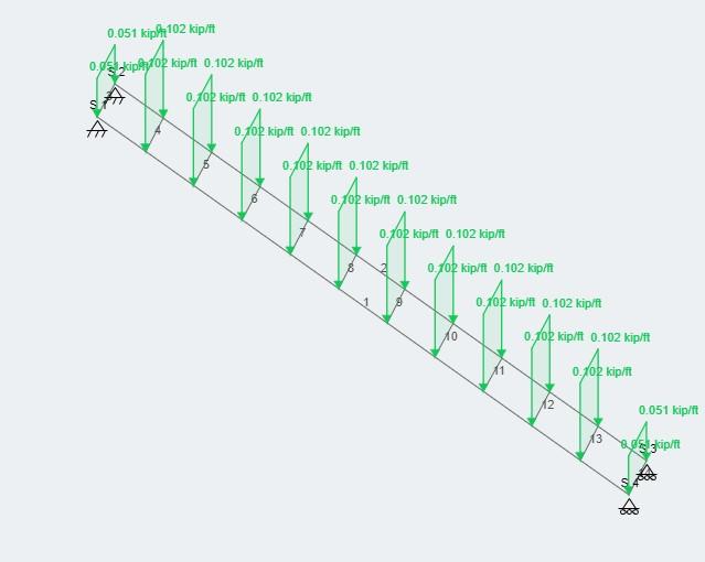
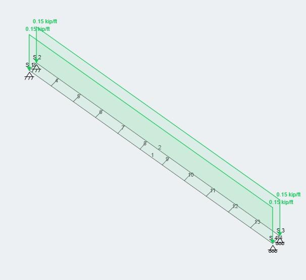
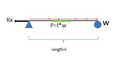
The stringers will face axial compression and bending moment (edwise and flatwise). Thus, need to design for bending in two directions and axial loading
Example of loading on one stringer (SkyCiv)
The 4 types of loads will need to be applied to the stringer differently:
Live Load
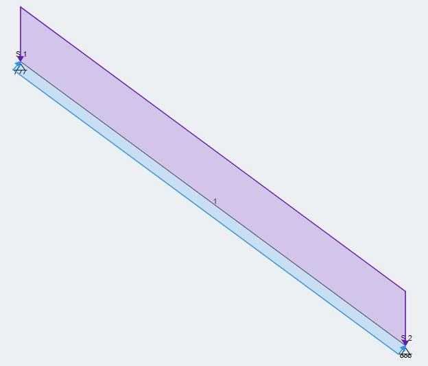
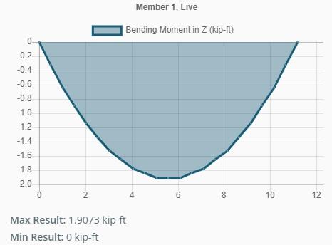
There is two ways of distributing the force. In the first assume load on the treads is being transferred to stringers. In the second, the loads are assumed to distributed load on both stringers. Tested out both cases in SkyCiv
Load Transferring to stringers
Stair Groups
CEA R:GAH 12/05/2022 9 of 28
Stair Calculation
Non-Commercial Use Only
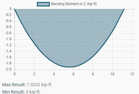
Load distributed on stringers
As can be seen from the two figures the maximum moment is almost the same, so will base calculations on load distributed on stringers This means tributary width will be half the width of tread
TW = .5⋅lt 1.5 ft
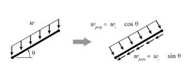
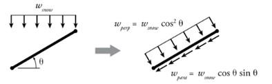
Since load causes both axial and bending, need find the axial and bending components. The bending will be in the edgewise case Angle of stairs, the stairs have a rise and run of:
rise 77 in
run 110 in
tan( (θ) ) tan( ( ⋅θ deg) )
Stair Groups Stair Calculation CEA R:GAH 12/05/2022 10 of 28
≔
≔
≔
≔θ → =
≔
Bending: ≔ wB( (q) ) ⋅ ⋅q TW cos( (θ) ) ≔ wL_B = wB⎛ ⎝qL⎞ ⎠ 0.123 kip ft Axial: ≔ wA( (q) ) ⋅ ⋅q TW sin( (θ) ) ≔ wL_A = wA⎛ ⎝qL⎞ ⎠ -0.063
Dead Load Non-Commercial Use Only
≔
tan( (x) ) ( (rise) ) run ,solve x atan⎛ ⎜ ⎝ 7 10 ⎞ ⎟ ⎠ deg =θ 34.992
cos( (θ) ) cos( ( ⋅θ deg) ) Now can find forces
kip ft
Dead Load
Will be just like the live load, since already account for tributary width, I divided weight by TW
Bending:
kip ft
Snow
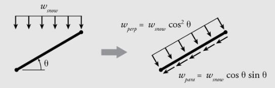
Snow load is along the horizontal projection of the member
kip ft
wS_A = ⋅
qs TW cos( (θ) ) sin( (θ) ) -0.01 kip ft
Wind
Wind will be perpendicular to surface, both causing edgewise and flatwise bending Found the pressure previously, but need to apply this to the surfaces that will be in contact with wind, which in this case includes the railings. The weight of railing is assumed negligible
Edgewise bending
The areas that are considered in edge wise bending is just the area of the tread (12 steps) and stringers
tt lt 12 2
ts ls 5.458 ft2 This means the force due to wind is:
AEdge = +
lbf
Not including torsion in calculation. Will assume this force will be distributed throughout the length of the stringer
ww_edge = Fw ls 0.025 kip ft
Flatwise bending
Stair Groups Stair Calculation CEA R:GAH 12/05/2022 11 of 28
≔ wD_B = wB ⎛ ⎜ ⎝ wD TW ⎞ ⎟ ⎠ 0.021
Axial: ≔ wD_A = wA ⎛ ⎜ ⎝ wD TW ⎞ ⎟ ⎠ -0.011 kip ft
≔
≔ wS_B = ⋅ ⋅ qs TW cos( (θ) ) 2 0.019
⋅ ⋅
≔
⋅ ⋅
⋅
≔ Fw = ⋅ AEdge Pz 270.803
≔
Non-Commercial Use Only
Flatwise bending
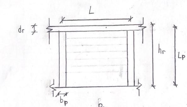
Railings ≔ hr 36 in Railing Height
bp 4 in Post thickness
br 1 in Railing Thickness
Total area that is covered by railing Since there is 4 posts and the length of the top bar is the length of the stringer, the total area covered by the railing is:
Not including torsion in calculation. Will assume this force will be distributed throughout the length of the stringer
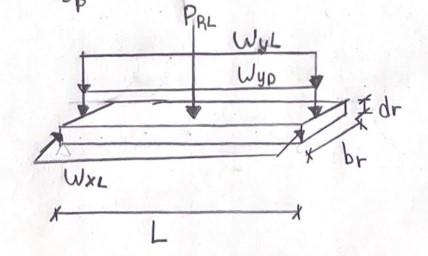
ww_flat = Fw ls 0.022 kip ft Now that have all the loads divided in terms of axial and bending can calculate applicable factored loads. Below are factored loads with their respective time factor, λ
Axial Case Factored Load (ASCE 7, 2.3) λ (NDS 2018, Table N3) 1
wu1A = 1.4⋅wD_A -0.015 kip ft
λ1 .6 2
wu2A = + + 1.2⋅wD_A 1.6⋅wL_A 0.5⋅wS_A -0.119 kip ft
λ2 .8 3
wu3A = + + 1.2⋅wD_A 1.6⋅wS_A wL_A -0.092 kip ft
λ3 .8 > > wu2A wu3A wu1A Since case 2 is the larger factored load will be basing calculations on this
Stair Groups Stair
CEA R:GAH 12/05/2022 12 of 28
Calculation
≔
≔
≔ AFlat = + ⋅ 4⋅bp hr ⋅ br ls 4.917 ft2 ≔ Fw = ⋅ AFlat Pz 243.93 lbf
≔
Bendingedgewise Non-Commercial Use Only
≔
≔
≔
≔
≔
≔
Bendingedgewise
Bending
flatwise
Only one case, since the only force is wind
wuF = ww_flat 0.022 kip ft
λ1 1 ReductionFactors used in this analysis. All from NDS, 2018 Factor Name Source Reasoning
CF 1.1 Size Factor 4.3.6 lumber is 4" thick but not more than 12" wide
CLflat 1 Beam Stability Factor 3.3.3 Depth does not exceed breath for flatwise case, refer to tread calc CLedge Beam Stability Factor 3.3.3 Depth exceed breadth (d>b) for edgewise case, need further calculation
Edge wise case Flat wise case
Ct 1 Temperature Factor 4.3.4 The structure will not experience sustained exposure of temps above 150F
CM 0.85 Wet Service Factor, bending Sup. 4B Since stairs outdoor, moisture will exceed 19% for extended periods of time
Stair Groups
CEA R:GAH 12/05/2022 13 of 28
Stair Calculation
Case Factored Load (ASCE 7, 2.3) λ (NDS 2018, Table N3) 1 ≔ wu1E = 1.4⋅wD_B 0.029 kip ft ≔ λ1 .6 2 ≔ wu2E = + + 1.2⋅wD_B 1.6⋅wL_B 0.5⋅wS_B 0.231 kip ft ≔ λ2 .8 3 ≔ wu3E = + + 1.2⋅wD_B 1.6⋅wS_B wL_B 0.178 kip ft ≔ λ3 .8 4 ≔ wu4E = + + + 1.3⋅wD_B ww_edge wL_B 0.5⋅wS_B 0.184 kip ft ≔ λ4 1 > > > wu2E wu4E wu3E wu1E Since case 2 is the larger factored load will be basing calculations on this
≔
≔
≔
≔
≔
Ci 1 Incising Factor 4.3.8 There are no incisions
≔
≔
≔
≔
Non-Commercial Use Only
bE = ts 3.5 in ≔ bF = bs 11.25 in
dE = bs 11.25 in ≔ dF = ts 3.5 in
Stair Groups Stair Calculation
CM 0.85 Since stairs outdoor, moisture will exceed 19% for extended periods of time
CEA R:GAH 12/05/2022 14 of 28
Cr 1 Repetitive Member Factor Sup. 4B stringers are not in contact
Cfuflat 1.2 Flat Use Factor Sup. 4B lumber is used flatwise
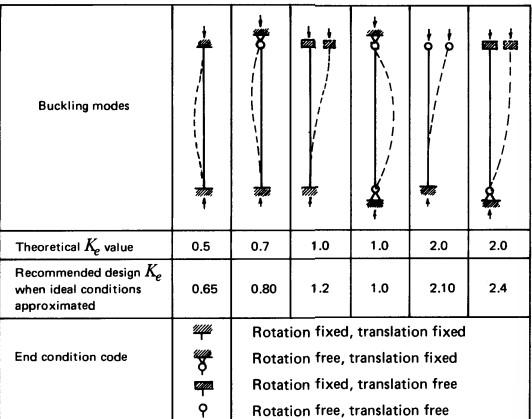
Cfuedge 1 Flat Use Factor Sup. 4B luber is used edgewise CP Column stability factor 3.7.1 equation will be below, requires other factors not calculated yet CT Buckling Stiffness Factor 4.4-1 equation will be below, requires other factors not calculated yet
Calculate reduction factors that have not been calculated Buckling Stiffness Factor CT (4.4-1)
Inputs
Assumptions
KM 1200 assuming wood is only partially seasoned
KT 0.59 vissually graded lumber
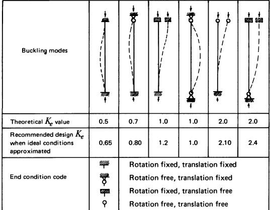
Ke 1 Buckling length coeffcieicent (NDS, 2018 Table G1). Assume rotation is free, but translation is fixed in both flat and narrow face
le1 = ⋅ Ke ls 11 ft Effective column length (3.7.1.2) Since le is greater than 96", then ≔ le1 96 in
⎛ ⎜ ⎝
KM le1 ft ⎞ ⎟ ⎠
CT = 1+
KT E psi
1.01 is unitless CT
Beam stability factor edgewise case CLedge
Distance between supports , will be the distance between treads, since rise and run of lu each step is 7" (rise) by 10" (run). will be lu
lu = ⎛ ⎝ + ( (10 in) ) 2 ( (7 in) ) 2 ⎞ ⎠
1 2 1.017 ft
Effective length for bending, (Table 3.3.3) le Since = lu dE 1.085 < lu dE 7 and assuming single span uniformly loaded
leb = 2.06⋅lu 2.095 ft
≔
≔
≔
≔
≔
≔
≔
≔
≔
⋅
⋅
≔
Non-Commercial Use Only
≔
Slenderness ratio (3.3-5) RB = dE 11.25 in ≔ RB = ⎛ ⎜ ⎜ ⎝ ⎛ ⎝ ⋅ leb dE⎞ ⎠ bE 2 ⎞ ⎟ ⎟ ⎠
1 2 4.805 Since slenderness ratio does not exceed 50, it is acceptable. This is slenderness of edgeface
Calculate (Table 4.3-1) ′ Emin ≔ Emin ' = ⋅ ⋅ ⋅ ⋅ ⋅ ⋅ Emin CM Ct Ci CT ( (1.76) ) ( (0.85) ) ⎛ ⎝8.863⋅105 ⎞ ⎠ psi
Calculate FbE ≔ FbE = 1.2⋅Emin ' RB 2 ⎛ ⎝4.606⋅104 ⎞ ⎠ psi reference bending design value multiplied by all applicable adjustment factors except Fb '' Cfu, and CL (see 2.3) ≔ Fb '' = ⋅ ⋅ ⋅ ⋅ ⋅ ⋅ ⋅ ⋅ ⋅ Fb Ci CF Ci Ct CM Cr 2.54 λ2 .85 2.907 ksi
Now can calculate CLedge ≔ CLedge = -
⎛ ⎜ ⎝ 1+ ⎛ ⎜ ⎝ FbE Fb '' ⎞ ⎟ ⎠ ⎞ ⎟ ⎠ 1.9
⎛ ⎜ ⎜ ⎜ ⎝
⎛ ⎜ ⎝ 1+ ⎛ ⎜ ⎝ FbE Fb '' ⎞ ⎟ ⎠ ⎞ ⎟ ⎠ 1.9
⎞ ⎟ ⎟ ⎟ ⎠
2 -
2 ⎛ ⎜ ⎝ FbE Fb '' ⎞ ⎟ ⎠ 0.95 0.997 3.3.3
Column Stability Factor CP (3.7.1) Will be different depending on edgewise or flatwise loading c factor needed in calculation ≔c 0.8 (sawn lumber, 3.7.1)
reference compression design value parallel to grain multiplied by all applicable adjustment Fc '' factors except CP
Fc '' = ⋅ ⋅
Fc CM Ct CF Ci 2.4 0.9 λ2 ⎛ ⎝2.827⋅103 ⎞ ⎠ psi ≔ Emin ' = ⋅ ⋅
Emin CM Ct Ci CT ( (1.76) ) ( (0.85) ) ⎛ ⎝8.863⋅105 ⎞ ⎠ psi Need to see which has the greater slenderness ratio
EdgeWise ≔ le1 = ⋅ Ke ls 11 ft (3.7.1.2) = le1 dE 11.733 (3.7.13) *Note slenderness ratio below 50, so acceptable
Stair Groups Stair Calculation CEA R:GAH 12/05/2022 15 of 28
≔
⋅ ⋅ ⋅ ⋅ ⋅
⋅ ⋅ ⋅ ⋅
Non-Commercial Use Only
FlatWise
Combinedbendingandaxialloading
Since the loads are not completely perpendicular to the stringers, need to look at both bending and axial forces
Main equation + + ⎛ ⎜ ⎝ P P' ⎞ ⎟ ⎠
2 M1 ⋅ M1 ' ⎛ ⎜ ⎝ 1-⎛ ⎜ ⎝ P PE1
⎞ ⎟ ⎠ ⎞ ⎟ ⎠
M2 ⋅ M2 ' ⎛ ⎜ ⎜ ⎝ - 1-⎛ ⎜ ⎝ P PE2
⎞ ⎟ ⎠ ⎛ ⎜ ⎝ M1 ME
⎞ ⎟ ⎠
2 ⎞ ⎟ ⎟ ⎠ (NDS 3.9-1)
= adjusted compression capacity P' =compressive force P =adjusted moment capacity (strong axis) M1 ' =bending moment (strong axis) M1 =ajusted moment capacity (weak axis) M2 ' =bending moment (weak axis) M2 = critical column buckling capacity(strong axis) PE1 =critical column buckling capacity(weak axis) PE2 =critical beam buckling capacity ME
First need moment capacity and buckling capacity related to flat (weak axis) and edgewise case (strong axis). The time factors were chosen previously in the load discussion section λ
Stair Groups Stair Calculation CEA R:GAH 12/05/2022 16 of 28
≔ le2 = ⋅ Ke ls 11 ft (3.7.1.2) = le2 dF 37.714 (3.7.13) *Note slenderness ratio below 50, so acceptable ≔ FcE2 = ⎛ ⎝0.822⋅Emin '⎞ ⎠ ⎛ ⎜ ⎝ le2 dF ⎞ ⎟ ⎠ 2 512.217 psi (NDS 3.7) ≔ CP =⎛ ⎜ ⎝ 1+ FcE2 Fc '' ⎞ ⎟ ⎠ 2 c 2⎛ ⎜ ⎜ ⎝ 1+ ⎛ ⎜ ⎝ FcE2 Fc '' ⎞ ⎟ ⎠ 2 ⎞ ⎟ ⎟ ⎠ 2 c ⎛ ⎜ ⎝ FcE2 Fc '' ⎞ ⎟ ⎠ c 0.091 (3.7.1)
Edge =λ λ2 ≔ Fb1 ' = ⋅ ⋅ ⋅ ⋅ ⋅ ⋅ ⋅ ⋅ ⋅ ⋅ Fb CM Ct CLedge CF Cfuedge Ci Cr 2.54 0.85 λ2 ⎛ ⎝2.897⋅10
⎠
≔ M1 ' = ⋅ Fb1 ' Sxx 17.825 ⋅kip ft
≔ FcE1 = ⎛ ⎝0.822⋅Emin '⎞ ⎠ ⎛ ⎜ ⎝ le1 dE ⎞ ⎟ ⎠ 2 ⎛ ⎝5.292⋅103 ⎞ ⎠ psi
≔ PE1 = ⋅ FcE1 A ⎛ ⎝2.084⋅105 ⎞ ⎠ lbfNon-Commercial(M3.9) Use Only
3 ⎞
psi (M4.3-1)
(M3.3)
(NDS 3.7)
Stair Groups Stair Calculation CEA R:GAH 12/05/2022 17 of 28 ⎛ ⎜ ⎝ le1 dE ⎞ ⎟ ⎠ ≔ PE1 = ⋅ FcE1 A ⎛ ⎝
=
≔
⋅ ⋅ ⋅ ⋅ ⋅ ⋅ ⋅ ⋅ ⋅ ⋅
≔
≔
= ⎛
⎛
≔
= ⋅
⎛
=λ λ2 ≔ Fc ' = ⋅ ⋅ ⋅ ⋅ ⋅ ⋅ ⋅ Fc
t
≔
⋅
c
(M3.3) Critical buckling capacity ≔ FbE = ⎛ ⎝1.2⋅Emin '⎞ ⎠ RB 2 ⎛ ⎝4.606⋅104 ⎞ ⎠ psi
≔ ME = ⋅ Sxx FbE 283.367 ⋅kip ft
Now calculate actual compressive force and bending moments Edgewise Assume
beam ≔ M1 = ⋅ wu2E ls 2 8 3.493 ⋅kip ft (AISC
≔ fb1 = M1 Sxx 0.568 ksi Flatwise ≔ M2 = ⋅ wuF ls 2 8 0.335 ⋅kip ft ≔ fb2 = M2 Sxx 0.055 ksi Compression Non-Commercial Use Only
2.084⋅105 ⎞ ⎠ lbf (M3.9) Flat
λ λ1
Fb2 ' =
Fb CM Ct CLflat CF Cfuflat Ci Cr 2.54 0.85 λ1 ⎛ ⎝4.36⋅103 ⎞ ⎠ psi (M4.3-1)
M2 ' = ⋅ Fb2 ' Syy 8.346 ⋅kip ft (M3.3)
FcE2
⎝0.822⋅Emin '⎞ ⎠
⎜ ⎝ le2 dF ⎞ ⎟ ⎠ 2 512.217 psi (NDS 3.7)
PE2
FcE2 A
⎝2.017⋅104 ⎞ ⎠ lbf (M3.9) Calculate adjusted compressive capacity Compression
CM C
CF Ci CP ( (2.40) ) ( (0.90) ) λ2 256.941 psi (M4.3-1)
P' =
F
' A ⎛ ⎝1.012⋅104 ⎞ ⎠ lbf
(ND7 3.9.2)
(M3.9)
simple
Table 3-23- Aid 1)
Stair Groups Stair Calculation CEA R:GAH 12/05/2022 18 of 28
Find maximum compression, since it is
evenly distributed
equation as = ΣFx 0 = - Rx ⋅ ls wu2A 0 = Rx ⋅ ls wu2A ≔x , ‥ 0 ft 0.1 ft ls ≔ N( (x) ) - ⋅ wu2A x ⋅ wu2A ls 0.3 0.45 0.6 0.75 0.9 1.05 1.2 0 0.15 1.35 2 3 4 5 6 7 8 9 10 0 1 11 x ( (ft) ) N( (x) )
) This means maximum
x=0 ≔P = N
≔ fc = P A 33.146 psi Checkallcases forBendingandaxialcompression = + + ⎛ ⎜ ⎝ P P' ⎞ ⎟ ⎠ 2 M1 ⋅ M1 ' ⎛ ⎜ ⎝ 1-⎛ ⎜ ⎝ P PE1 ⎞ ⎟ ⎠ ⎞ ⎟ ⎠ M2 ⋅ M2 ' ⎛ ⎜ ⎜ ⎝ - 1-⎛ ⎜ ⎝ P PE2 ⎞ ⎟ ⎠ ⎛ ⎜ ⎝ M1 ME ⎞ ⎟ ⎠ 2 ⎞ ⎟ ⎟ ⎠ 0.257 (NDS 3.9-1) This is less than1,thus passes case = + fc FcE2 ⎛ ⎜ ⎝ fb1 FbE ⎞ ⎟ ⎠ 2 0.065 (NDS 3.9-4) This is less than1,thus passes case = FcE1 5.292 ksi Non-Commercial Use Only
Compression
a
axial load, could describe
( (kip)
is at
( (0 ft) ) 1.305 kip
= FcE1 5.292 ksi
Calculation CEA R:GAH
< fc FcE1
= fc 0.033 ksi (NDS 3.9.2)
sincethisistruepassescase < fc FcE1
= FcE2 0.512 ksi
= fc 0.033 ksi
< fc FcE2 (NDS 3.9.2)
sincethisistruepassescase < fc FcE2
= FbE 46.057 ksi
= fb1 0.568 ksi
< fb1 FbE (NDS 3.9.2)
sincethisistruepassescase < fb1 FbE
Memberpasses allcases,thedimensions chosenareappropriate
CalculateCapacityofColumn,makesuredimensions chosenareappropriate Non-Commercial Use Only
12/05/2022 19 of 28
Stair Groups Stair
Southern Pine Dense Select Structural NDS Supplement (Table 4D)
Southern Pine Dense Select Structural NDS Supplement (Table 4D)
Southern Pine Dense Select Structural NDS Supplement (Table 4D) Non-Commercial Use Only
Stair Groups
CEA R:GAH 12/05/2022 20 of 28
≔
≔
≔
T
≔ lL
≔ Syy
≔ Sxx =
yy
≔ Iyy
≔ Ixx =
yy
≔
Stair Calculation
CalculateCapacityofColumn,makesuredimensions chosenareappropriate 6in X 6in Column: Standard Dressed Dimensions: Material: Southern Pine Dense Select Structural
bC 5.5 in
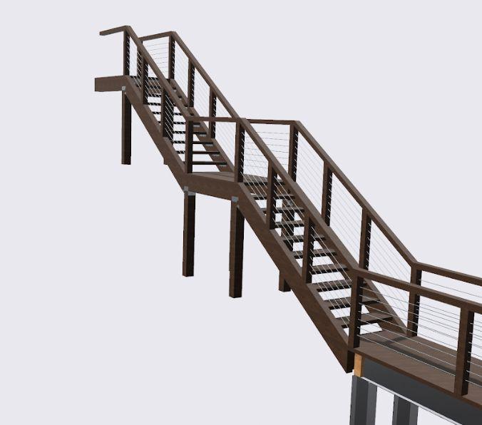
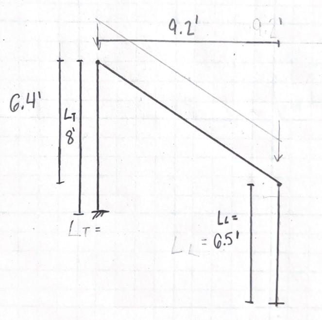
dC = bC 5.5 in The length of each column is different, this analysis chose to analyze the stairs with the longest columns, since these will be the ones facing most forces.
l
8 ft Column length top of stair
6.5 ft Column length bottom of stair =rise 6.417 ft =run 9.167 ft Since top stair column are longer, will look at this one for this analysis Column in Red Sketch of Stair Section Properties: Assuming that the wood is timber, since larger than 5"x5" Property Source
27.73 in3 Section Modulus NDS Supplement (Table 1B)
S
27.73 in3
76.26 in4 Moment of Inertia NDS Supplement (Table 1B)
I
76.26 in4
E 1600000 psi Modulus of Elasticity
≔
Emin 580000 psi Minimum Modulus of Elasticity
≔ Fb
1750 psi Bending design
Fb 1750 psi
Fc 1100 psi
Bending design
Comp. parallel to grain
Southern Pine Dense Select Structural NDS Supplement (Table 4D)
Southern Pine Dense Select Structural NDS Supplement (Table 4D)
A 30.25 in2 Area of Section NDS Supplement (Table 1B)
Specific Gravity
Density water
Loads
Southern Pine Dense Select Structural NDS Supplement (Table 4D)
To simplify calculation, since there is 4 columns per stair case will assume that each column will recieve 1/4th of the total load of the stair and 1/4 of the landing loads
ll 6 ft Width of Landing
Length of Landing
wl = lt 3 ft
To do this will make all loads either parallel (acting axially) or perpendicular (bending) on the column
Live and Dead
Live and Dead loads are already parallel with length of column. Therefore can use live and dead loads calculated in stringer calculations. Need to just multiply by the appropriate factor
We know the dead load on each stringer, since there are 2 stringers the total dead load due to stringers is
kip ft
The dead load of each stringer of the landing, since there are 2 stringers the total dead load due to stringers is
ft 6
Dead load on each column, will then be the total dead load times the length of the stringers PD Non-Commercial Use Only
Stair Groups
CEA
12/05/2022 21 of 28
Stair Calculation
R:GAH
≔
≔
≔
≔SG .55
≔ ρw 62.4 lbf ft3
≔
≔
≔
≔
wD_S = wD 0.025 kip ft
wD_ST = 2⋅wD_S 0.05
≔
⋅
≔
wD_L = + ⎛ ⎜ ⎝
wDt ll bt ⎞ ⎟ ⎠ 2 wDt 0.04 kip
wD_LT 2⋅wD_S
Dead load on each column, will then be the total dead load times the length of the stringers PD ≔ PD = + ⋅ wD_ST ls ⋅ wD_LT ll 4 0.214 kip
Live load will be similar, but using a pressure instead. Multiply pressure by the width of the stair case (width of stair case is the same as width of landing) and the length of stringers (both stringers in the landings and stairs) = qL 0.694 psi Live load on each column, PL ≔ PL = ⋅ qL ⎛ ⎝ + ⋅ lt ls ⋅ ll lt⎞ ⎠ 4 1.275 kip
Snow
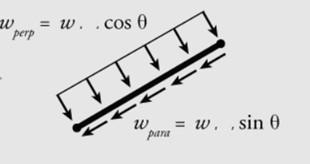
Process to make stair stringer snow load parallel to column. In the stringer calculation already did the first step for the stair stringer = wS_B 0.019 kip ft ≔ wS_par = wS_B cos( (θ) ) 0.023 kip ft The landing snow load will be perpendicular to the surface. This was calculated in tread calculation = qs 0.131 psi
Now find point load ≔ PS = + ⋅ ⋅ wS_par ls 2 4 ⎛ ⎝ ⋅ ⋅ qs lt ll⎞ ⎠ 4 0.213 kip
Wind Assume wind is only acting perpendicular to column, thus it is only on the surface area of the column =Pz 0.345 psi ≔ ww = ⋅Pz bC 0.023 kip ft
Stair Groups
CEA R:GAH 12/05/2022 22 of 28
Stair Calculation
Non-Commercial Use Only
Now that have all the loads can can calculate applicable factored loads. Below are factored loads with their respective time factor, λ
2018, Table N3)
λ3 .8 Since case 3 is the larger factored load will be basing calculations on this
Pu3A = + + 1.2⋅PD 1.6⋅PS PL 1.873 kip
Bending Only one case, since the only force is wind
λ1 1 ReductionFactors used in this analysis. All from NDS, 2018 Factor Name Source Reasoning
Ci 1 Incising Factor 4.3.8 There are no incisions
CF 1 Size Factor 4.3.6 lumber is more than 5" thick but not more than 12" wide
CL 1 Beam Stability Factor 3.3.3 Depth does not exceed breath for flatwise case, refer to tread calc = bC 0.458 ft = dC 0.458 ft
Ct 1 Temperature Factor 4.3.4 The structure will not experience sustained exposure of temps above 150F
CM 1 Wet Service Factor Sup. 4B Southern Pine use tabulated design values without further adjustment
C
1 Repetitive Member Factor Sup. 4B not applicable to column Non-Commercial Use Only
Stair Groups
CEA R:GAH 12/05/2022 23 of 28
Stair Calculation
≔
Axial Case Factored Load (ASCE 7, 2.3) λ (NDS
1 ≔ Pu1A = 1.4⋅PD 0.3 kip ≔ λ1 .6 2 ≔ Pu2A = + + 1.2⋅PD 1.6⋅PL 0.5⋅PS 2.404 kip ≔ λ2 .8 3
≔
≔
≔
wuF = ww 0.023 kip ft
≔
≔
≔
≔
≔
≔
r
Stair Groups Stair
CEA R:GAH 12/05/2022 24 of 28 ≔
r
≔
≔
≔
≔
e
≔ le1 = ⋅
e l
≔ CT =
⎛ ⎜ ⎝ ⋅ KM le1 ft ⎞ ⎟ ⎠ ⋅ KT E
≔
c ''
≔ Fc '' = ⋅ ⋅ ⋅ ⋅ ⋅ ⋅ ⋅ Fc CM Ct
F
i
λ3 ⎛ ⎝
≔ Emin ' = ⋅ ⋅ ⋅ ⋅ ⋅ ⋅ Emin CM Ct Ci CT (
) (
) ⎛ ⎝
⎞ ⎠
Calculation
C
1 Repetitive Member Factor Sup. 4B not applicable to column
Cfu 1 Flat Use Factor 4.3.7 lumber is used square, thus does not have wide or edge face CP Column stability factor 3.7.1 equation will be below, requires other factors not calculated yet CT Buckling Stiffness Factor 4.4-1 equation will be below, requires other factors not calculated yet Calculate reduction factors that have not been calculated Buckling Stiffness Factor CT (4.4-1) Inputs Assumptions
KM 1200 assuming wood is only partially seasoned
KT 0.59 vissually graded lumber
K
2.1 Buckling length coefficient (NDS, 2018 Table G1). Assume rotation is free, but translation is fixed in the bottom and rotation and translation free at top. Using reccomened value
K
T 201.6 in Effective column length (3.7.1.2) Since le is greater than 96", then is unitless CT
1+
psi 1.021 Column Stability Factor CP 3.7.1 c factor needed in calculation
c 0.8 (sawn lumber, 3.7.1) reference compression design value parallel to grain multiplied by all applicable adjustment F
factors except CP
C
C
2.4 0.9
1.901⋅103 ⎞ ⎠ psi
(1.76)
(0.85)
8.862⋅105
psi Non-Commercial Use Only
Combinedbendingandaxialloading
There will be both bending and axial forces on columns. Worst case would be if wind causes bending in two directions
Main equation ≤ + + ⎛ ⎜ ⎝ P P' ⎞ ⎟ ⎠ M1 M1 '⎛ ⎜ ⎝ 1-⎛ ⎜ ⎝ P PE1
⎞ ⎟ ⎠ ⎞ ⎟ ⎠
= adjusted compression capacity P' =compressive force P
M2 Fb2 ' ⎛ ⎜ ⎜ ⎝ - 1-⎛ ⎜ ⎝ P PE2
⎞ ⎟ ⎠ ⎛ ⎜ ⎝ M1 ME
=adjusted moment capacity (strong axis) M1 '
=bending moment (strong axis) M1
=ajusted moment capacity (weak axis) M2 ' =bending moment (weak axis) M2
= critical column buckling capacity(strong axis) PE1
=critical column buckling capacity(weak axis) PE2
=critical beam buckling capacity ME
⎞ ⎟ ⎠
2 ⎞ ⎟ ⎟ ⎠
1 (NDS 3.9-1)
First need moment capacity and buckling capacity. The columns are square, thus there is no strong or weak axis The time factors were chosen previously in the load discussion section λ
Stair Groups Stair Calculation CEA R:GAH 12/05/2022 25 of 28 ≔ Fc '' = ⋅ ⋅ ⋅ ⋅ ⋅ ⋅ ⋅ Fc CM Ct CF Ci 2.4 0.9 λ3 ⎛ ⎝1.901⋅103 ⎞ ⎠ psi ≔ Emin ' = ⋅ ⋅ ⋅ ⋅ ⋅ ⋅ Emin CM Ct Ci CT ( (1.76) ) (
) ⎛ ⎝8.862⋅105 ⎞ ⎠
≔ le1 = ⋅ Ke lT 16.8 ft
= le1 d
≔ FcE2 = ⎛ ⎝0.822⋅Emin '⎞ ⎠ ⎛ ⎜ ⎝ le2 dF ⎞ ⎟ ⎠ 2 512.149
≔ CP =⎛ ⎜ ⎝ 1+ FcE2 Fc '' ⎞ ⎟ ⎠ 2
(0.85)
psi Slenderness ratio
(3.7.1.2)
C 36.655 (3.7.13) *Note slenderness ratio below 50, so acceptable Final value before calculationCP
psi (NDS 3.7)
c 2⎛ ⎜ ⎜ ⎝ 1+ ⎛ ⎜ ⎝ FcE2 Fc '' ⎞ ⎟ ⎠ 2 ⎞ ⎟ ⎟ ⎠ 2 c ⎛ ⎜ ⎝ FcE2 Fc '' ⎞ ⎟ ⎠ c 0.216 (3.7.1)
Non-Commercial Use Only
Bending =λ λ1 ≔ Fb1 ' = ⋅ ⋅ ⋅ ⋅ ⋅ ⋅ ⋅ ⋅ ⋅ ⋅ Fb CM Ct CL CF Cfu Ci Cr 2.54 0.85 λ1 ⎛ ⎝3.778⋅103 ⎞ ⎠ psi (M4.3-1) ≔ M1 ' = ⋅ Fb1 ' Sxx 8.731 ⋅kip ft (M3.3) ≔ FcE1 = ⎛ ⎝0.822⋅Emin '⎞ ⎠ ⎛ ⎜ ⎝ le1 dE
⎞ ⎟ ⎠
2 ⎛ ⎝2.268⋅103 ⎞ ⎠ psi (NDS 3.7) ≔ PE1 = ⋅ FcE1 A ⎛ ⎝6.862⋅104 ⎞ ⎠ lbf (M3.9)
Since there is no strong or weak axis ≔ M2 ' = M1 ' 8.731 ⋅kip ft ≔ FcE2 = FcE1 ⎛ ⎝2.268⋅103 ⎞ ⎠ psi ≔ PE2 = PE1 ⎛ ⎝6.862⋅104 ⎞ ⎠ lbf
Need to calculate slenderness ratio
Distance between supports , will be the length of column lu ≔ lu = lT 8 ft
Effective length for bending, (Table 3.3.3) le Since = lu dC 17.455 > lu dC 7 and assuming single span uniformly loaded ≔ le = + 1.63⋅lu 3⋅dC 14.415 ft
Slenderness ratio (3.3-5) RB
⎝
⎜ ⎜ ⎝
Compression
le dC⎞ ⎠ bC 2 ⎞ ⎟ ⎟ ⎠
RB =
1 2 5.608 Since slenderness ratio does not exceed 50, it is acceptable. This is slenderness of edgeface
Stair Groups Stair Calculation CEA R:GAH 12/05/2022 26 of 28
≔
⎛
⎛
⋅
=
≔
'
⋅ ⋅ ⋅ ⋅ ⋅ ⋅ ⋅ F
≔
⋅
Critical
capacity Non-Commercial Use Only
λ λ3
Fc
=
c CM Ct CF Ci CP ( (2.40) ) ( (0.90) ) λ2 410.269 psi (M4.3-1)
P' =
Fc ' A ⎛ ⎝1.241⋅104 ⎞ ⎠ lbf (M3.3)
buckling
Critical buckling capacity ≔ FbE = ⎛ ⎝1.2⋅Emin '⎞ ⎠ RB 2 33.813 ksi (ND7 3.9.2) ≔ ME = ⋅ Sxx FbE 78.136 ⋅kip ft (M3.9)
Now calculate actual compressive force and bending moments Compression ≔P = Pu3A ⎛ ⎝1.873⋅103 ⎞ ⎠ lbf ≔ fc = P A 61.911 psi
Bending- assume simple beam ≔ M1 = ⋅ wuF lT 2 8 0.182 ⋅kip ft (AISC Table 3-23- Aid 1) ≔ fb1 = M1 Sxx 78.722 psi
Same for both sides of column ≔ M2 = M1 0.182 ⋅kip ft ≔ fb2 = fb1 78.722 psi
Checkallcases forBendingandaxialcompression = + + ⎛ ⎜ ⎝ P P' ⎞ ⎟ ⎠
2 M1 ⋅ M1 ' ⎛ ⎜ ⎝ 1-⎛ ⎜ ⎝ P PE1
M2 ⋅ M2 ' ⎛ ⎜ ⎜ ⎝ - 1-⎛ ⎜ ⎝ P PE2
⎛ ⎜ ⎝ fb1 FbE
⎞ ⎟ ⎠
⎞ ⎟ ⎠ ⎞ ⎟ ⎠
⎞ ⎟ ⎠ ⎛ ⎜ ⎝ M1 ME
⎞ ⎟ ⎠
2 ⎞ ⎟ ⎟ ⎠
2 0.027 (NDS 3.9-4)
0.066 (NDS 3.9-1) This is less than1,thus passes case = + fc FcE2
This is less than1,thus passes case = FcE1 2.268 ksi < fc FcE1 = fc 0.062 ksi (NDS 3.9.2) sincethisistruepassescase < fc FcE1
Stair Groups Stair
CEA R:GAH 12/05/2022 27 of 28
Calculation
= FcE2 2.268 ksi Non-Commercial Use Only
= FcE2 2.268 ksi
= fc 0.062 ksi
< fc FcE2 (NDS 3.9.2)
sincethisistruepassescase < fc FcE2
= FbE 33.813 ksi
= fb1 0.079 ksi
< fb1 FbE (NDS 3.9.2)
sincethisistruepassescase < fb1 FbE
Memberpasses allcases,thedimensions chosenareappropriate
CEA R:GAH 12/05/2022 28 of 28
Stair Groups Stair Calculation
Non-Commercial Use Only
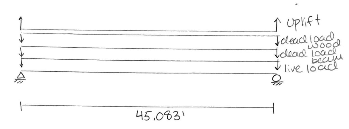
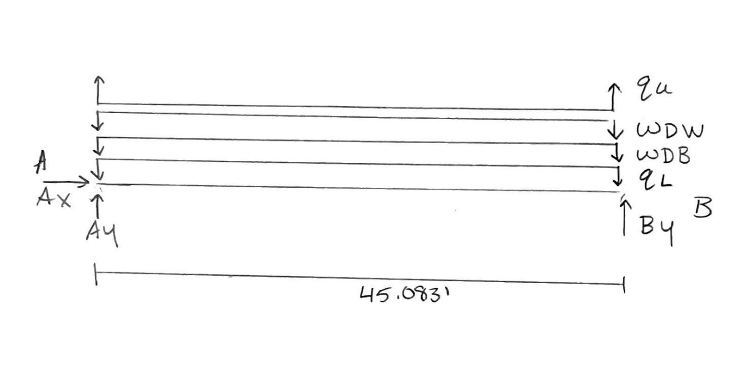
Stair Group Bridge Calculations GAH, R:CEA 11/04/2022 1 of 17 DeterminerequiredI-beamforgirdersthroughLRFDandconfirmbridgeis structurallysound Diagram ≔L 45.083 ft ≔b 3 ft ≔x , ‥ 0 ft 1 ft b variable range for width ≔z , ‥ 0 ft 1 ft L variable range for length
LiveLoad ≔ qL 90 psf LRFD
≔ wL = ⋅ qL b 2 0.135 kip ft Area Load
Design
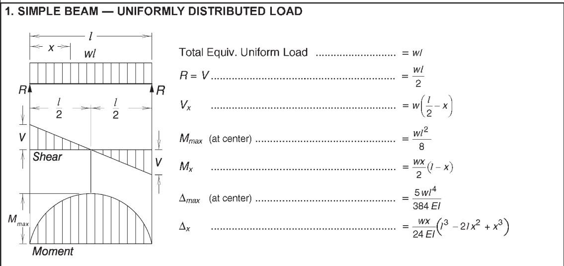
#1 AISC
≔ RLa = ⋅ wL L 2 3.043 kip ≔ RLb =⋅ wL L 2 -3.043 kip ≔ VLmax = RLa 3.043 kip Non-Commercial Use Only
FBD
Specifications of Pedestrian Bridges (3.1 Pedestrian Loading)
to Distributed Load
Aid
Table 3.23
2 Wwood
Wwood 10.665 plf Convert to plf along nominal width, then add weight of 45' wood to support railings Design Aid #1 AISC Table 3.23
Stair Group Bridge Calculations GAH, R:CEA 11/04/2022 2 of 17 ≔ RLb =⋅ wL L 2
≔ V
= RLa
≔
L(
z) ) ⋅ wL z
) ≔
= ⋅ w
⋅
≔ρ
≔
≔
≔
≔
≔
≔
⋅
≔ R
= ⋅
≔ RDWb =⋅
≔ VDWmax = R
≔ MDW( (z) ) ⋅ ⋅W z
≔ M
= ⋅
2
⋅
Non-Commercial Use Only
-3.043 kip
Lmax
3.043 kip
M
(
2 ( ( -L z)
MLmax
L L2 8 34.298
kip ft DeadLoadWood SouthernPine#22x12
34.35 pcf Stairs Calculation
Wwood 4.102 plf weight of 2x12 wood NDS Supplement (Table 1B)
nw 11.25 in nominal width of 2x12
nh 1.5 in nominal height of 2x12
nnotrounded = L nw 48.089 number of 2x12 needed
n 49 number of 2x12 rounded up
W = +
b
nw
DWa
W L 2 0.24 kip
W L 2 -0.24 kip
DWa 0.24 kip
2 ( ( -L z) )
DWmax
W L
8 2.71
kip ft
DeadLoadBeam
Wi 16 plf AISC Table 1-1 Beam W12x16 =L 45.083 ft Design Aid #1 AISC Table 3.23
Uplift LRFD Guide Specifications for the Design of Pedestrain Bridges (Section 3.4 Wind Loads)
Design Aid #1
AISC Table 3.23
Stair Group
GAH,
11/04/2022 3 of 17
Bridge Calculations
R:CEA
≔
≔
≔
≔
≔
≔
RDBa = ⋅ Wi L 2 0.361 kip
RDBb =⋅ Wi L 2 -0.361 kip
VDBmax = RDBa 0.361 kip
MDB( (z) ) ⋅ ⋅ Wi z 2 ( ( -L z) )
MDBmax = ⋅ Wi L2 8 4.065 ⋅kip ft
≔
≔ qU 0.02 ksf
wU = ⋅ qU b 2 0.03 klf
≔
≔
Non-Commercial Use Only
RUa = ⋅ wU L 2 0.676 kip
RUb =⋅ wU L 2 -0.676 kip ≔ VUmax = RUa 0.676 kip
Kd .85 Directionality Factor AASHTO Signs, 3.8,5-1 Assume support type is overhead frame/truss, this is also the lowest factor
G 1.14 Gust Effect Facotor AASHTO Signs, 3.8.6 this is the minimum number
Cd 2.0 Drag Coeffciient AASHTO Signs, 3.8.7 Assume two member or trusses Wind pressure Equation :Pz
Stair Group Bridge Calculations GAH, R:CEA 11/04/2022 4 of 17 ≔ RUb =⋅ wU L 2
≔ V
=
≔
( (z) ) ⋅ ⋅ wU z
≔
⋅
⋅
≔
≔
≔
≔
≔
≔
⋅ ⋅ ⋅ ⋅
≔
≔
≔
⋅
≔
⋅
Non-Commercial Use Only
-0.676 kip
Umax
RUa 0.676 kip
MU
2 ( ( -L z) )
MUmax =
wU L2 8 7.622
kip ft WindLoad Variable Name Source Reasoning
V 100 mph 300-Year MRI Basic Wind Speed AASHTO Signs, 3.8-3b Used map
Kz 1 Height and Exposure Factor AASHTO Signs, 3.8,4-1 Height less than 33 feet
Pz = ⋅
0.00256 Kz Kd G V2 Cd psf mph2 49.613 psf (AASHTO Signs, 3.8.1-1) =L 45.083 ft
d 12 in height of I-beam
Wwind = ⋅Pz d 49.613 plf Design Aid #1 AISC Table 3.23
RWa =
Wwind L 2 1.118 kip
RWb = -
Wwind L 2 -1.118 kip
CombineDesignAids
Load and Resistance Factor Design (LRFD Method) ≤ Ru φRn AISC 360 Eq. (B3-1)
Ru = required strenth of a member subjected to strength design load combinations = resistance factor φ Rn = nominal strength of the member as determined by the specifcations Rn = design strength φ
CombinationofLoads
Load Combinations Strength II, Strength IV, and Strength V do not need to be considered (LRFD Guide Specifications for the Design of Pedestrian Bridges)
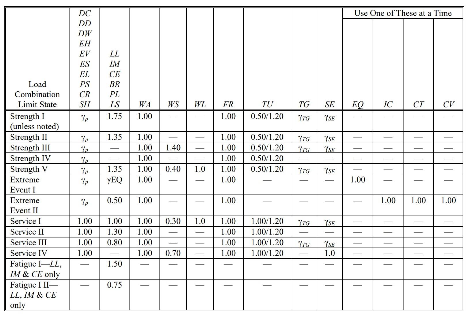
AASHTO Table 3.4.1-1
AASHTO Table 3.4.1-2
Stair Group Bridge Calculations GAH, R:CEA 11/04/2022 5 of 17
≔
≔ VWmax = RWa ? kip
MW( (z) ) ⋅ ⋅ Wwind z 2 ( ( -L z) ) ≔ MWmax = ⋅ Wwind L2 8 12.605 ⋅kip ft
Non-Commercial Use Only
Table 3.4.1-2
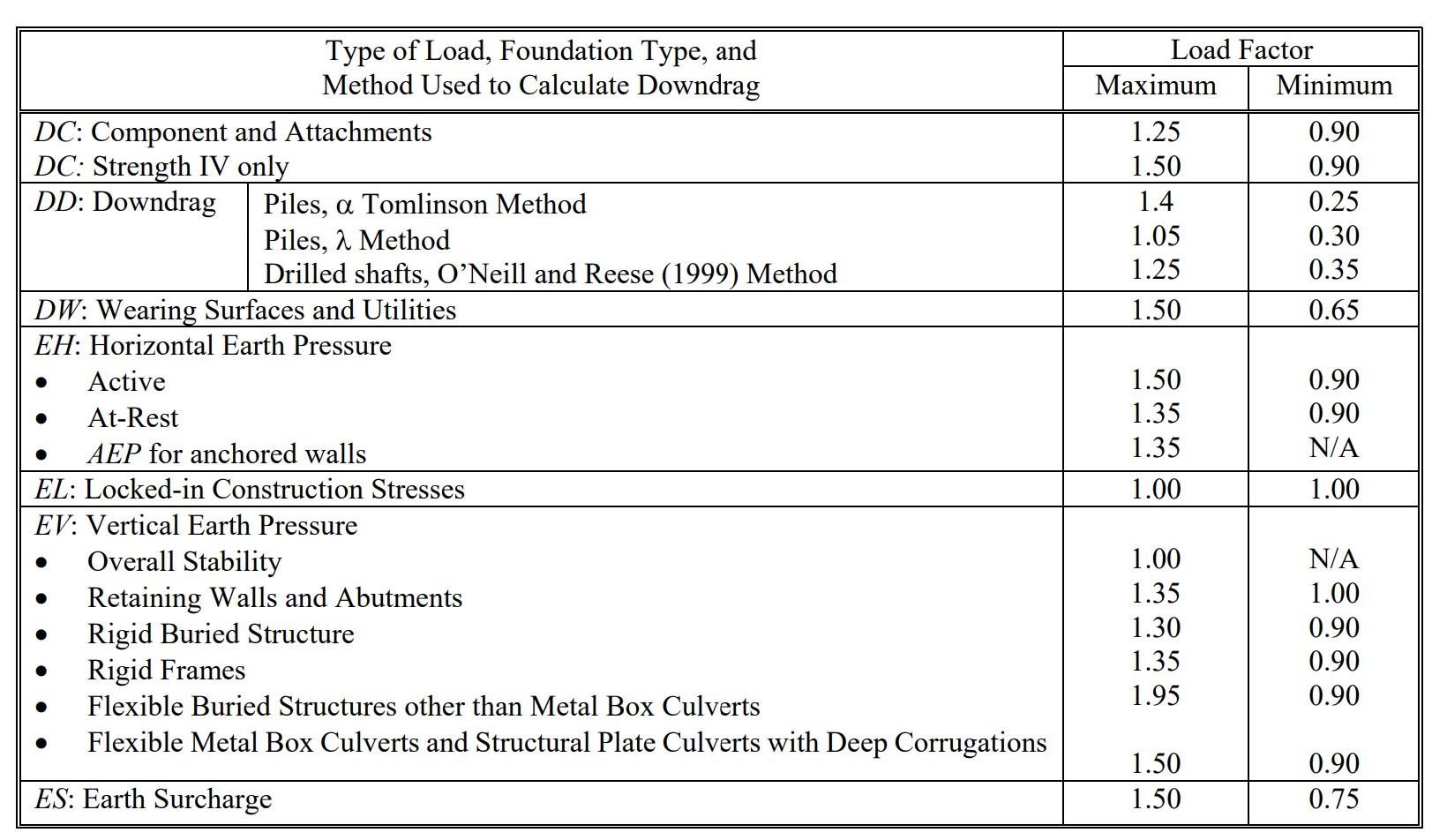
Strength I - Basic load combination relating to the normal use without wind ≔ γp 1.25 vertical: ≤ + ⋅ γp DC 1.75⋅LL φRn shear: ≔ VStrength1 = - + + 1.25⋅VDWmax 1.25⋅VDBmax 1.75⋅VLmax 1.75⋅VUmax 4.893 kip moment: ≔ MStrength1 = - + + 1.25⋅⎛ ⎝MDWmax⎞ ⎠ 1.25⋅MDBmax 1.75⋅MLmax 1.75⋅MUmax 55.152 ⋅kip ft
Strength III - Load combination relating to structure exposed to wind velocity exceeding 55 mph vertical: ≤ ⋅ γp DC φRn shear: ≔ VStrength3V = + 1.25⋅⎛ ⎝VDWmax⎞ ⎠ 1.25⋅VDBmax 0.751 kip moment: ≔ MStrength3V = + 1.25⋅⎛ ⎝MDWmax⎞ ⎠ 1.25⋅MDBmax 8.468 ⋅kip ft horizontal: ≤ 1.4⋅WS φRn shear: ≔ VStrength3H = 1.4⋅VWmax 1.566 kip moment: ≔ MStrength3H = 1.4⋅MWmax 17.646 ⋅kip ft
Service I - Load combination reltaing to the normal operational use of the bridge with a 55 mph wind ≤ + 1.00⋅DC 0.80⋅LL φRn vertical: Non-Commercial Use Only
Stair Group Bridge Calculations GAH, R:CEA 11/04/2022 6 of 17
AASHTO
vertical: ≤ + 1.00⋅DC 0.80⋅LL φRn shear: ≔ VService1V = - + + 1.00⋅⎛ ⎝VDWmax⎞ ⎠ 1.00⋅VDBmax 0.80⋅VLmax 0.8⋅VUmax 2.495 kip moment: ≔ MService1V = - + + 1.00⋅⎛ ⎝MDWmax⎞ ⎠ 1.00⋅MDBmax 0.80⋅MLmax 0.8⋅MUmax 28.116 ⋅kip ft horizontal: ≤ 0.3⋅WS φRn shear: ≔ VService3H = 0.3⋅VWmax 0.336 kip moment: ≔ MService3H = 0.3⋅MWmax 3.781 ⋅kip ft
CheckMaximumShearandMoment
Vertical: > > VStrength1 VService1V VStrength3V > > MStrength1 MService1V MStrength3V ≔ Vu = VStrength1 4.893 kip ≔ Mu = MStrength1 55.152 ⋅kip ft
Horizontal: > VStrength3H VService3H > MStrength3H MService3H ≔ VuH = VStrength3H 1.566 kip ≔ MuH = MStrength3H 17.646 ⋅kip ft
Stair Group
R:CEA 11/04/2022 7 of 17
Bridge Calculations GAH,
Non-Commercial Use Only
Select Type of Steel Corrosion Resistant Steel needed for outdoors Refer to AISC Table 2-4 Applicable ASTM Specifications for Various Structural Shapes A588Steel is Corrosion Resistant High-Stength Low-Alloy Steel with good Fy and Fu, and can be used in W I beams
Design of Steel Beams in Flexure Find minimum Zx required to withstand moment
Design of Steel Beams for Shear Find minimum Aw required to withstand shear
Stair Group Bridge Calculations GAH, R:CEA 11/04/2022 8 of 17
≔
≔
Fy 50⋅ksi minimum yield stress
Fu 70 ksi minimum tensile strength
⋅
=
n ⋅
≤
⋅ ⋅
≔
⋅
≔
x
⋅
≤ Mu
φ Mn Zx = plastic section modulus about the x-axis
M
Fy Zx
Mu
φ Fy Zx
φb 0.90 resistance factor for flexure ≤ Mu
φ Fy Zx Solve for Zx
Z
= Mu
φb Fy 14.707 in3 mimimum Zx value
=
⋅
≔
≤
⋅ ⋅ ⋅φ
≤
u ⋅ ⋅ φ
≔
⋅ ⋅
≤ Vu φVn
Vn
0.6⋅Fy Aw Aw = web area, overall depth times the web thickness
φv 1.0 resistance factor for shear
Vu
0.6 Fy Aw from V(x) diagram
V
v 0.6 Fy Aw Solve for Aw
Aw = Vu
φv 0.6 Fy 0.163 in2 minimum Aw value Look at AISC Table 1-1 W-Shape I-Beams to find beam with minimum Zx and Aw values Non-Commercial Use Only
Look at AISC Table 1-1 W-Shape I-Beams to find beam with minimum Zx and Aw values
Choose smallest beam possible: save weight and money = Zx 14.707 in3 = Aw 0.163 in2
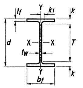
W12x16beam ≔ Zxx 20.1 in3 ≔ tw 0.22 in web thickness ≔d 12 in height ≔ Aw = ⋅ tw d 2.64 in2
Properties of W12x16 beam (AISC Table 1-1) ≔ Abeam 4.71 in2 area ≔d 12 in total height = tw 0.22 in web thickness ≔ bf 3.99 in flange width ≔ tf 0.265 in flange thickness ≔T 10.375 in web height ≔ Ixx 103 in4 moment of inertia about x-axis ≔ Sxx 17.1 in3 elastic section modulus about x-axis ≔ Zxx 20.1 in3 plastic section modulus about x-axis ≔ Iyy 2.82 in4 moment of inertia about y-axis ≔ Syy 1.41 in3 elastic section modulus about y-axis ≔ Zyy 2.26 in3 plastic section modulus about y-axis ≔J 0.103 in4 torsional constnat ≔ Cw 96.9 in6 warping constant
Confirmwoodplankarestructurallysound
Diagram: FBD
Stair
11/04/2022 9 of 17
Group Bridge Calculations GAH, R:CEA
Non-Commercial Use Only
Bridge
GAH, R:CEA 11/04/2022 10 of 17 =
≔
= ⋅ ⋅
=
≔
= ⋅
≔
= ⋅
=
≔
⋅
= ∑
=
⋅
⋅
⋅
⋅
≔
⋅
⋅
⋅
= ∑
=
≔
=
≔
≔
⋅
≔
≔
≔
≔
≔
≔
≔
≔
≔
≔
≔
≔
≔
Non-Commercial Use Only
Calculations
qU 0.02 ksf uplift area load
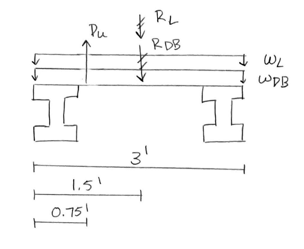
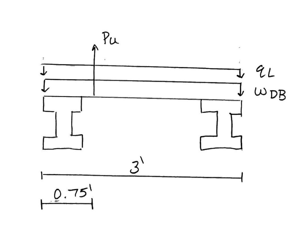
PU
qU L b 2.705 kip uplift point load acting L/4 from the windward side of bridge
qL 90 psf
wLplank
qL L 4.057 klf distributed live load across 3ft
RL
wLplank b 12.172 kip
W 0.011 klf distributed dead load for wood
RDB =
W b 0.032 kip Left side is A, Right side is B
MA 0
+ + +
PU 0.75 ft
-RL 1.5 ft
-RDB 1.5 ft
By 3 ft 0
By = + +
-PU 0.75 ft
RL 1.5 ft
RDB 1.5 ft 3 ft 5.426 kip
Fy 0
+ - - + Ay PU RL RDB By 0
Ay
- - + RL RDB PU By 4.073 kip Since > By Ay
Vplankmax = By 5.426 kip
Mplankmax
3.558 kip ft 2x12 Wood Plank Properties NDS Supplement (Table 1B)
Awood 16.88 in2
Sxx 31.64 in3
Ixx 178 in4
Syy 4.218 in3
Iyy 3.164 in4 Southern Pine Dense Select Structural Design Values 12" Wide NDS Supplement (Table 4B)
Fb 1800 psi Bending
Ft 1250 psi Tension parallel to grain
Fv 175 psi Shear parallel to grain
Fcperp 660 psi Compression perpendicular to grain
Fc 1750 psi Compression parallel to grain
E 1900000 psi Modulus of elasticity
Emin 690000 psi Modulus of elasticity minimum
G 0.55 Specific gravity
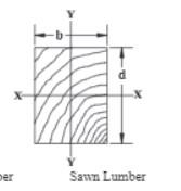
CalculateCapacityofTreads,makesuredimensions chosenareappropriate
Dimensions tread:
tt 2 in height
bt 12 in width
lt 3 ft length *Dimensions are based on DCA6 for stair treads
SectionProperties: Assuming that the wood can be considered Decking, since intended for floor use and wide face in contact with supporting members.
Property Source
Syy 4.219 in3 Section Modulus NDS Supplement (Table 1B)
Iyy 3.164 in4 Moment of Inertia NDS Supplement (Table 1B)
E 1900000 psi Modulus of Elasticity Southern Pine No. 2 NDS Supplement (Table 4B) = Fb ⎛ ⎝1.8⋅103 ⎞ ⎠ psi Bending design Southern Pine No. 2 NDS Supplement (Table 4B) = Fv 175 psi Shear Parallel Southern Pine No. 2 NDS Supplement (Table 4B) = Awood 0.117 ft2 Area of Section NDS Supplement (Table 1B)
Pine No. 2 NDS Supplement (Table 4B)
Pine
Supplement
1 Importance Factor ASCE 7, Table 1.5-2
Stair Group Bridge Calculations GAH, R:CEA 11/04/2022 11 of 17
≔
≔
≔
≔
≔
≔
≔G .55 Specific Gravity Southern
≔ ρw 62.4 lb ft3 Density water ≔ pb = ⋅ ⋅ ρw ⎛ ⎜ ⎝ G ( (1+ ⋅G ( (0.009 .19))) ) ⎞ ⎟ ⎠ ⎛ ⎜ ⎝ 1+ .19 100 ⎞ ⎟ ⎠ 34.353 lb ft3
≔
≔
≔
≔
s
≔ qs
⋅ ⋅ ⋅
Non-Commercial Use Only
Density of Southern
(NDS
3.13) Loads Given Loads: Name Source ≔ qL 90 psf Live weight (IBC Section 1604.3) Find snow load
qg 25 psf snow load ground ASCE 7-16
Ct 1.2 Thermal Factor ASCE 7, Table 7-3
Ce .9 Terrain B, exposure factor ASCE 7-2
I
=
0.7⋅Ce Ct Is qg 0.131 psi snow load on surface ASCE 7.3-1
Find distributed loads
wL
qL bt 0.09 kip ft Live
wD = 4.102 lbf ft 0.004 kip ft Dead, based on density of wood (NDS Supplement-Table 1B) pb
ws =
qs bt 0.019 kip ft Snow
wU 0.03 kip ft
wT = + wL wD 0.094 kip ft Total Applicable factored load governs with their respective time factor, λ Case Factored Load (ASCE 7, 2.3) λ (NDS 2018, Table N3) 1
wu1 = 1.4⋅wD 0.006 kip ft
λ1 .6 2
wu2 = + + + 1.2⋅wD 1.6⋅wL 0.5⋅ws 1.2⋅wU 0.194 kip ft
λ2 .8 3
wu3 = + + + 1.2⋅wD 1.6⋅ws wL 1.2⋅wU 0.161 kip ft
λ3 .8 ReductionFactors used in this analysis. All from NDS, 2018 Factor Name Source Reasoning
Ci 1 Incising Factor 4.3.8 There are no incisions
CF 1 Size Factor 4.3.6 lumber does not exceed 12" wide and it is not 4" thick
CL 1 Beam Stability Factor 3.3.3 Depth does not exceed breadth (d<b), in flatwise loading
b = bt 1 ft
d = tt 2 in
Ct 1 Temperature Factor 4.3.4 structure will not experience sustained exposure of temps >150F
CMb 0.85 Wet Service Factor, bending Sup. 4B Since stairs outdoor, moisture will exceed 19% for extended periods of time
CMv 0.97 Wet Service Factor, shear Sup. 4B
Repetitive Member Factor Sup. 4B treads are not in contact Non-Commercial Use Only
Stair
11/04/2022 12 of 17
Group Bridge Calculations GAH, R:CEA
≔
r
≔
= ⋅
≔
≔
⋅
=
≔
≔
≔
≔
≔
≔
≔
≔
≔
≔
≔
≔
≔
≔
≔
C
1
Now can calculate M'
Stair Group Bridge Calculations GAH, R:CEA 11/04/2022 13 of 17 ≔
r
≔
≔ M'⎛ ⎝Fb '⎞ ⎠ ⋅ Fb '
yy
≔ Fb '( (λ) ) ⋅ ⋅ ⋅ ⋅ ⋅ ⋅ ⋅ ⋅ ⋅ ⋅ ⋅ Fb Ci CF CL Ci Ct CMb Cr
fu 2.54
≔ Fb1 ' = Fb '⎛ ⎝λ1⎞ ⎠ ⎛ ⎝2.378⋅103 ⎞ ⎠
≔ Fb2 ' = Fb '⎛ ⎝λ2⎞ ⎠ ⎛ ⎝3.171⋅103 ⎞
≔
C
1 Repetitive Member Factor Sup. 4B treads are not in contact
Cfu 1.2 Flat Use Factor Sup. 4B lumber is used flatwise, load applied to wide face Flexure Assume that the threads are Bending Members, since they will be primarly in flexure Calculate Adjusted Moment Capacity (M')
S
(M3.3-2) Equation for Adjusted bending design Fb', given different load combinations (NDS, 2018 Table N3)
C
λ .85 (Table M4.3-1)
psi
⎠ psi
Fb3 ' = Fb '⎛ ⎝λ3⎞ ⎠ ⎛ ⎝3.171⋅103 ⎞ ⎠ psi
≔
≔
≔
≔
u
u
⋅
u
≔
u
≔
≔
≔
≔
Shear Non-Commercial Use Only
M1 ' = M'⎛ ⎝Fb1 '⎞ ⎠ 0.836 ⋅kip ft
M2 ' = M'⎛ ⎝Fb2 '⎞ ⎠ 1.115 ⋅kip ft
M3 ' = M'⎛ ⎝Fb3 '⎞ ⎠ 1.115 ⋅kip ft Calculate Factored bending moment for the three load combinations
M
⎛ ⎝w
⎞ ⎠
w
lt 2 8 (Factored max moment, assume simple beam) (AISC Table 3-23- Aid 1)
Mu1 = M
⎛ ⎝wu1⎞ ⎠ 0.006 ⋅kip ft
Mu2 = Mu⎛ ⎝wu2⎞ ⎠ 0.219 ⋅kip ft
Mu3 = Mu⎛ ⎝wu3⎞ ⎠ 0.181 ⋅kip ft SinceM'>Muforallthreecases,itis acceptable (M3.3-1) Checkslendernessratio RB Effective length (Table 3.3.3)
le = + 1.63⋅lt 3⋅d 5.39 ft
RB = ⎛ ⎜ ⎝ ⎛ ⎝ ⋅ le d⎞ ⎠ b2 ⎞ ⎟ ⎠ 1 2 0.948 Less than50,soacceptable
Shear
simple beam, AISC Table 3-23- Aid 1)
Deflection
Stair Group Bridge Calculations GAH, R:CEA 11/04/2022 14 of 17
≔
≔
⋅
⋅
⋅
≔
≔
≔
≔
≔
≔
Calculate Adjusted Shear Capacity, V'
V'⎛ ⎝Fv '⎞ ⎠ ⋅ ⋅ 2 3 Fv ' A (M3.4-3) Calculate Adjusted shear design Fv' for given load combinations
Fv '( (λ) )
⋅ ⋅
⋅
Fv CMv Ct Ci 2.7 .8 λ (Table M4.3-1)
Fv1 ' = Fv '⎛ ⎝λ1⎞ ⎠ 219.996 psi
Fv2 ' = Fv '⎛ ⎝λ2⎞ ⎠ 293.328 psi
Fv3 ' = Fv '⎛ ⎝λ3⎞ ⎠ 293.328 psi Calculate V'
V1 ' = V'⎛ ⎝Fv1 '⎞ ⎠ 21.12 ⋅ A ft2 kip
V2 ' = V'⎛ ⎝Fv2 '⎞ ⎠ 28.159 ⋅ A ft2 kip
V3 ' = V'⎛ ⎝Fv3 '⎞ ⎠ 28.159 ⋅ A ft2 kip Calculate factored bending moment for the three load combinations ≔ Vu⎛ ⎝wu⎞ ⎠ ⋅ wu lt 2 (Assume
≔ Vu1 = Vu⎛ ⎝wu1⎞ ⎠ 0.009 kip ≔ Vu2 = Vu⎛ ⎝wu2⎞ ⎠ 0.292 kip ≔ Vu3 = Vu⎛ ⎝wu3⎞ ⎠ 0.242 kip SinceV'>Vuforallthreescenarionsthisis acceptable (M3.4-1)
≔
⎛
⋅
≔
⎛
⋅
⋅
Non-Commercial Use Only
Deflection limits (Source IBC Table 1604.3) Deflection Midspan- uniformely loaded Live Load = lt 240 0.15 in
ΔL =
⎝ ⋅ 5⋅wL lt 4 ⎞ ⎠
384⋅E Iyy 0.027 in (M3.5-1) Total Load = lt 360 0.1 in
ΔT =
⎝
5⋅wT lt 4 ⎞ ⎠
384⋅E Iyy 0.029 in Sincethelimits arelargerthanthedeflections,this is acceptable
Find
Flexural Buckling of Member without Slender Elements
Vu = VStrength1 4.893 kip check if Pn is greater than Vu
Stair Group Bridge Calculations GAH, R:CEA 11/04/2022 15 of 17
requiredI-beamforColumnswithLRFD Compression Limit State = Fe ⋅ π 2 E ⎛ ⎜ ⎝ ⋅K L r ⎞ ⎟ ⎠ 2 elastic critical buckling stress ≔E 29000 ksi modulus of elasticity ≔K 2.0 effective length factor Steel Structures Design Table 6.3 ≔ rxx 4.91 in radius of gyration for W12x22 ≔ ryy 2.31 in radius of gyration for W12x22 ≔ Lc 7 ft length of column ≔ Fe = ⋅ π 2 E ⎛ ⎜ ⎝ ⋅K Lc ryy ⎞ ⎟ ⎠ 2 54.113 ksi table 4-1 = ⋅K Lc ryy 72.727 slenderness ratio = 4.71⋅⎛ ⎜ ⎝ E Fy ⎞ ⎟ ⎠ 0.5 113.432 = ⋅K Lc 14 ft Inelastic buckling governs when < ⋅K Lc ryy 4.71⋅⎛ ⎜ ⎝ E Fy ⎞ ⎟ ⎠ 0.5
≔
Inelastic Buckling = Fcr 0.877⋅Fe elastic critical stress ≔ Fcr = 0.877⋅Fe 47.457 ksi AISC 360 Eq (E3-3) ≔ Ag 9.12 in2 gross area of member ≔ Pn = ⋅ Fcr Ag 432.81 kip nominal compressive strength AISC 360 Eq (E3-1)
≔ Pc
⋅ Pn
Non-Commercial Use Only
Elastic buckling ≔κ Fy Fe ≔ FEcr = ⋅ 0.658κ Fy 33.964 ksi ≔ PEn = ⋅ FEcr Ag 309.747 kip ⋅ φc Pn design compressive strength
=
0.9 389.529 kip
⎛ ⎜ ⎝ Mr MweakMax
⎞ ⎟ ⎠ 0.806 AISC Eq. H1-1b Less than1,thus acceptable
⎞ ⎟ ⎠ 1.0 = + Pr 2⋅Pc Non-Commercial Use Only
⎛ ⎜ ⎝ Mr MweakMax
Stair Group
11/04/2022 16 of 17 ⋅ φc Pn
Bridge Calculations GAH, R:CEA
≔ Pc = ⋅ Pn 0.9 389.529 kip Table 6-1 AISC Page 6-3 Axial Compression LRFD Formula ≔p = 1 Pc 0.003 1 kip Use KL =14ft to find p and bx on Table 6-1 W12x22 greater than design value ≔ ptable = 26.8 103 kip 0.027 1 kip coefficient for axial compression related to combined axial and bending strength ≔ bx = 24.5 ⋅ ⋅ 103 kip ft 0.025 1 ⋅kip ft coefficient for strong axis being related to combined axial and bending strength Assume strong axis bending ≔ MweakMax ⋅ 13.7 kip ft AISC Table 3-4 W12x22 Page 3-24 ≔ Pr = Vu 4.893 kip required axial compressive strength = Pc 389.529 kip available axial compressive strength = VuH 1.566 kip ≔ Mr = ⋅ VuH Lc 131.518 ⋅kip in required flexural strength = Pr Pc 0.013 Doubly and Singly Symmetric Members in Flexure and Compression Page 16.1-71 ≤ + Pr 2⋅Pc
PropertiesofMaterialsUsed
Type of Steel A588Steel is Corrosion Resistant High-Stength Low-Alloy Steel with good Fy and Fu, and can be used in W I beams
Fy 50⋅ksi minimum yield stress ≔ Fu 70 ksi minimun tensile strength
I-Beam Properties (AISC Table 1-1)
W12x22
Abeam 4.71 in2
W12x22
Abeam 6.48 in2 area
d 12 in =d 12.3 in total height = tw 0.22 in = tw 0.26 in web thickness = bf 3.99 in = bf 4.03 in flange width = tf 0.265 in = tf 0.425 in flange thickness
T 10.375 in =T 10.375 in web height
Ixx 103 in4
Ixx 156 in4 moment of inertia about x-axis
Sxx 25.4 in3 elastic section modulus about x-axis = rxx 4.67 in = rxx 4.91 in = Zxx 20.1 in3 = Zxx 29.3 in3 plastic section modulus about x-axis
Sxx 17.1 in3
Iyy 2.82 in4
Iyy 4.66 in4 moment of inertia about y-axis
Syy 1.41 in3 = Syy 2.31 in3 elastic section modulus about y-axis
ryy 0.773 in = ryy 0.848 in = Zyy 2.26 in3 = Zyy 3.66 in3 plastic section modulus about y-axis
J 0.103 in4 =J 0.293 in4 torsional constnat
Cw 96.9 in6
Syy 4.218 in3
Stair Group Bridge Calculations GAH, R:CEA 11/04/2022 17 of 17
≔
≔
≔
≔
Select Structural Design Values 12" Wide NDS Supplement
≔
Bending ≔
Tension
grain ≔
Shear
grain ≔
grain ≔
≔
≔
≔
Non-Commercial Use Only
=
=
=
=
=
=
=
=
=
=
=
=
=
=
= Cw 164 in6 warping constant 2x12 Wood Plank Properties NDS Supplement (Table 1B)
Awood 16.88 in2 ≔ Sxx 31.64 in3 ≔ Ixx 178 in4
Iyy 3.164 in4 Southern Pine Dense
(Table 4B)
Fb 1800 psi
Ft 1250 psi
parallel to
Fv 175 psi
parallel to
Fcperp 660 psi Compression perpendicular to
Fc 1750 psi Compression parallel to grain
E 1900000 psi Modulus of elasticity
Emin 690000 psi Modulus of elasticity minimum
G 0.55 Specific gravity
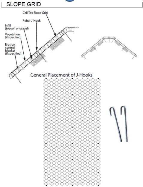
RailingCalculation
These calculations will be based on AASHTO LRFD Bridge Design Specification (2010), pedestrian railings.
Sketch
Dimensions of Railing
Post spacings are different for the landings, the two different stair types, and the bridge. All railings have the same connections and material, thus this calculation will focus on the railing with the largest post spacing. This is because this will lead to the largest live loads. If the railing is sufficient for the area with the largest post spacing, it will also be sufficient for areas with smaller post spacings.
L = 70 in 5.833 ft post spacing
h
36 in Height to top of railing
4 in Railing breadth, nominal
3 in Railing depth, nominal The calculation will be divided into two steps: Longitudinal Elements (the railing) and the posts
d
1.Longitudinal
Stair Groups Railing Calculation CEA R: GAH 12/05/22 1 of 14
≔
≔
≔
rn
≔
r
b
rn
Material: Dense Select Structural Southern Pine SectionProperties Property Source ≔ br
in breadth NDS Supplement
≔ dr
depth NDS Supplement
≔A
Area NDS Supplement
≔ Syy
Section
≔
xx
≔
yy
Non-Commercial Use Only
Element:
3.5
(Table 1B)
2.5 in
(Table 1B)
8.75 in2
(Table 1B)
5.1 in3
Modulus, strong axis NDS Supplement (Table 1B)
S
3.646 in3 Section Modulus, weak axis NDS Supplement (Table 1B)
I
8.932 in4 Moment of Inertia, strong axis NDS Supplement (Table 1B)
SectionProperties Property Source
wyL 0.05 kip ft Vertical Distributed Live Load (AASHTO 13.8.2)
2.127 lbf ft Vertical Dead Load for a density of 35 lb ft3 (NDS Supplement-Table 1B)
Stair Groups Railing Calculation CEA R: GAH 12/05/22 2 of 14
≔
xx
≔
≔
b
≔
c
≔
≔
min
≔ ρw
≔ pb = ⋅ ⋅ ρw ⎛ ⎜ ⎝
(
⋅G
⎞ ⎟ ⎠ ⎛ ⎜ ⎝
⎟ ⎠
≔
≔
≔
≔
≔
I
4.557 in4 Moment of Inertia, weak axis NDS Supplement (Table 1B)
G .55 Specific Gravity NDS Supplement (Table 4B)
F
2700 psi Bending design NDS Supplement (Table 4B)
F
2050 psi Comp parallel to grain NDS Supplement (Table 4B)
E 1900000 psi Modulus of Elasticity NDS Supplement (Table 4B)
E
690000 psi Min. Modulus of Elasticity NDS Supplement (Table 4B)
62.4 lb ft3 Density water
G
(1+
( (0.009 .19))) )
1+ .19 100 ⎞
0.131 lb ft3 Density of Southern Pine (NDS Supplement 3.13) Loads: Name: Source:
wxL 0.05 kip ft Transveral Distributed Live Load (AASHTO 13.8.2)
PRL 0.29 kip Vertical Live Point Load (AASHTO 13.8.2)
wxD 0 kip ft Tranversal Dead Load (no dead load horizontally)
wyD
Figure: Applicablefactoredload governs with their respective timefactor, λ Non-Commercial Use Only
Stair Groups Railing Calculation CEA R: GAH 12/05/22 3 of 14
(Using
Case
λ 1 ≔ wuy1 =
w
≔ λ
≔ wux1 =
2 ≔ wuy2 =
w
≔ λ
≔ wux2 =
wxD
≔ Pu2 = 1.6⋅PRL
3 ≔ wu3 = + 1.2⋅wyD wyL
≔ λ3
≔ Pu3 = 1⋅PRL 990.981 ⋅psi kip > > wux2 wux3 wuy1 > > wuy2 wuy3 wuy1 > > Pu2 Pu3 Pu1 Will use case
largest
≔ wux wux2 ≔ wuy wuy2 ≔ Pu Pu2 ReductionFactors NDS, 2018 Factor Name Source Reasoning ≔ Ci 1 Incising Factor 4.3.8 There are no incisions ≔ CF 1 Size Factor 4.3.6 lumber is 4"
≔ CLflat 1 Beam Stability Factor 3.3.3 Depth
not
calc CLedge Beam Stability Factor 3.3.3 Depth
Edge wise case Flat wise case ≔ bE = dr 2.5 in ≔ bF = br 3.5 in ≔ dE = br 3.5 in ≔ dF = dr 2.5 in ≔ Ct 1 Temperature Factor 4.3.4 The structure will not experience sustained exposure of temps
150F ≔ CM 0.85 Wet Service Factor, bending Sup. 4B Since
outdoor, moisture will
for
time ≔ Cr 1 Repetitive Member Factor Sup. 4B Railing is not in contact ≔ Cfuflat 1.1 Flat Use Factor Sup. 4B lumber
Non-Commercial
Applicablefactoredload governs with their respective timefactor, λ
NDS and ASCE, because they include bending in both directions)
Factored Load (ASCE 7, 2.3)
1.4⋅
yD 0.003 kip ft
1 .6
1.4⋅wxD ?
+ 1.2⋅
yD 1.6⋅wyL 0.083 kip ft
2 .8
+ 1.2
1.6⋅wxL 0.08 kip ft
? kip
0.053 kip ft
.8
2, since
P and w
thick but less than 8" wide
does
exceed breath for flatwise case, refer to tread
exceed breadth (d>b) for edgewise case, need further calculation
above
stairs
exceed 19%
extended periods of
is used flatwise, but the depth is less than 2"
Use Only
Cfuflat 1.1 Flat Use Factor Sup. 4B lumber is used flatwise, but the depth is less than 2"
Cfuedge 1 Flat Use Factor Sup. 4B lumber is used edgewise CT Buckling Stiffness Factor 4.4-1 equation will be below, requires other factors not calculated yet Calculate reduction factors that have not been calculated Buckling Stiffness Factor CT (4.4.-1)
Inputs Assumptions
KM 1200 assuming wood is only partially seasoned
KT 0.59 visually graded lumber
Ke 1 Buckling length coefficient (NDS, 2018 Table G1). Assume rotation and translation is fixed in both direction
le =
Ke L 70 in Effective column length (3.7.1.2) (Effective length assumed same in edge and flat wise case) = le dE 20 (3.7.13) *Note slenderness ratio below 50, so acceptable = le dF 28 (3.7.13) *Note slenderness ratio below 50, so acceptable Since le is less than 96", then
Beam stability factor edgewise case CLedge Distance between supports will be the distance between posts
lu =L 5.833 ft = dE 3.5 in Effective length for bending, (Table 3.3.3). Assuming single span with loading conditions not le specified in Table 3.3.3 Since = lu dE 20 and > lu dE 7 ≔ leb = 1.84⋅lu 10.733 ft Slenderness ratio (3.3-5) RB
Stair Groups Railing Calculation CEA R: GAH 12/05/22 4 of 14 ≔ Cr 1
≔
≔
≔
≔
≔
≔
⋅
≔ CT = 1+ ⎛ ⎜ ⎝ ⋅ KM le 1 in ⎞ ⎟ ⎠ ⋅ KT E psi 1.075
Use Only
≔
Non-Commercial
Slenderness ratio (3.3-5) RB
1 2 8.493 Since slenderness ratio does not exceed 50, it is acceptable. This is slenderness of edgeface Calculate (Table 4.3-1) ′ Emin ≔ Emin ' = ⋅ ⋅
RB = ⎛ ⎜ ⎜ ⎝ ⎛ ⎝ ⋅ leb dE⎞ ⎠ bE 2 ⎞ ⎟ ⎟ ⎠
Emin CM Ct Ci CT ( (1.76) ) ( (0.85) ) 943.151 ksi Calculate FbE ≔ FbE = 1.2⋅Emin ' RB 2 15.691 ksi reference bending design value multiplied by all applicable adjustment factors except Fb '' Cfu, and CL (see 2.3)
⋅
Now can calculate CLedge ≔ CLedge = -
⎛ ⎜ ⎝ 1+ ⎛ ⎜ ⎝ FbE Fb '' ⎞ ⎟ ⎠ ⎞ ⎟ ⎠ 1.9
⎛ ⎜ ⎜ ⎜ ⎝
⎛ ⎜ ⎝ 1+ ⎛ ⎜ ⎝ FbE Fb '' ⎞ ⎟ ⎠ ⎞ ⎟ ⎠ 1.9
⎞ ⎟ ⎟ ⎟ ⎠
2 -
2 ⎛ ⎜ ⎝ FbE Fb '' ⎞ ⎟ ⎠ 0.95 0.984 3.3.3
Now that have all applicable reduction factors can find the design values for combined bending
Combinedbending
Since the loads are both tranverse and vertical to railing need to look at combined bending
Main
Stair Groups Railing Calculation CEA R: GAH 12/05/22 5 of 14
≔
⋅
⋅ ⋅
≔ Fb '' = ⋅ ⋅ ⋅ ⋅ ⋅ ⋅ ⋅ ⋅ ⋅ Fb Ci CF Ci Ct CM Cr 2.54 λ2 .85 ⎛ ⎝3.964⋅103 ⎞ ⎠ psi
⎛ ⎜ ⎝ P P' ⎞ ⎟ ⎠ M
M
⎛ ⎜ ⎝ 1-⎛ ⎜ ⎝
PE1 ⎞ ⎟ ⎠ ⎞ ⎟ ⎠
M
⎛ ⎜ ⎜ ⎝ - 1-⎛ ⎜
Non-Commercial Use Only
equation ≤ + +
1
1 '
P
M2
2 '
⎝ P PE2 ⎞ ⎟ ⎠ ⎛ ⎜ ⎝ M1 ME ⎞ ⎟ ⎠ 2 ⎞ ⎟ ⎟ ⎠ 1 (NDS 3.9-1) = adjusted compression capacity P' =compressive force P =adjusted moment capacity (strong axis) M1 ' =bending moment (strong axis) M1 =ajusted moment capacity (weak axis) M2 ' =bending moment (weak axis) M2 = critical column buckling capacity(strong axis) PE1 =critical column buckling capacity(weak axis) PE2 =critical beam buckling capacity ME ≔P 0 kip (assume no axial) ≤ + M1 ⋅ M1 ' ( (1) ) M2 ⋅ M2 ' ⎛ ⎜ ⎜ ⎝ 1⎛ ⎜ ⎝ M1 ME ⎞ ⎟ ⎠ 2 ⎞ ⎟ ⎟ ⎠ 1 Since P=0, equation becomes
Stair Groups Railing Calculation CEA R: GAH 12/05/22 6 of 14 M1 ( (1) ) ⋅ M2 ' ⎛ ⎜ ⎜ ⎝
⎛ ⎜ ⎝ M1
E ⎞ ⎟ ⎠ ⎞ ⎟ ⎟ ⎠
=
≔
'
⋅ ⋅ ⋅ ⋅ ⋅ ⋅ ⋅ ⋅ ⋅ ⋅
≔
' = ⋅
⋅
=λ
≔
' = ⋅ ⋅ ⋅ ⋅ ⋅ ⋅ ⋅ ⋅ ⋅ ⋅
0.85 λ2 4.36 ksi
≔ M2 ' = ⋅ Fb2 ' Sxx 1.325 ⋅kip
≔ FbE = ⎛ ⎝1.2⋅Emin '⎞ ⎠ RB 2 15.691
≔ ME = ⋅ Syy FbE 6.669 ⋅
≔ M1 = ⋅ wux L2 8 0.34 ⋅
≔ fb1 =
yy
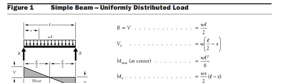
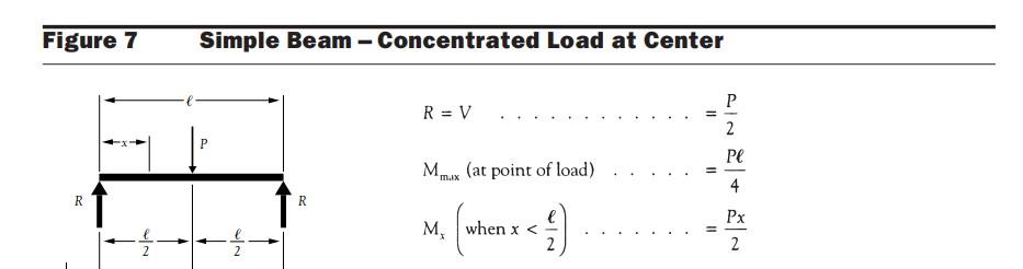
≔ V2( (x) ) + ⋅ wuy ⎛ ⎜ ⎝L 2 x ⎞ ⎟ ⎠ P 2 Use
of V to
≔ x0 → = V2( (x) ) 0 ,solve x ,float 3 2.92⋅ft ≔ M2( (x) ) + ⋅ ⋅ wuy x 2 ( ( -L x) ) ⋅ Pu x 2 ≔ M2 = M2⎛ ⎝x0⎞ ⎠ 1.029 ⋅kip ft ≔ fb2 = M2 Sxx 3.385 ksi Non-Commercial Use Only
1-
M
First need moment capacity and buckling capacity related to flat (weak axis) and edgewise case (strong axis). The time factors were chosen previously in the load discussion section λ Edge
λ λ2
Fb1
=
Fb CM Ct CLedge CF Cfuedge Ci Cr 2.54 0.85 λ2 ⎛ ⎝3.899⋅103 ⎞ ⎠ psi (M4.3-1)
M1
Fb1 ' Syy 1.657
kip ft (M3.3) Flat
λ2
Fb2
Fb CM Ct CLflat CF Cfuflat Ci Cr 2.54
(M4.3-1)
ft (M3.3) Critical buckling capacity
ksi (ND7 3.9.2)
kip ft (M3.9) Now calculate actual compressive force and bending moments Edgewise-Only uniform load Assume simple beam
kip ft (Design Aid 6, Figure 1 and 8)
M1 S
0.801 ksi Flatwise-Uniform load and point load at center
zero crossing
find max moment
Checkallcases forBending = + M1 ⋅ M1 ' ( (1) ) M2 ⋅ M2 ' ⎛ ⎜ ⎜ ⎝ 1⎛ ⎜ ⎝ M1 ME
⎞ ⎟ ⎠
2 ⎞ ⎟ ⎟ ⎠
0.984 (NDS 3.9-1)
This is less than1,thus passes case = ⎛ ⎜ ⎝ fb1 FbE
⎞ ⎟ ⎠
2 0.003 (NDS 3.9-4)
This is less than1,thus passes case = FbE 15.691 ksi < fb1 FbE (NDS 3.9.2) = fb1 0.801 ksi sincethisistruepassescase < fb1 FbE
Memberpasses allcases,thedimensions chosenareappropriate
Stair Groups Railing Calculation CEA R: GAH 12/05/22 7 of 14
1.Posts: Non-Commercial Use Only
Stair Groups Railing Calculation CEA R: GAH 12/05/22 8 of 14
≔ bp
≔ dp
≔A
≔ Syy
≔ Sxx
≔ Iyy
≔ Ixx
≔G
≔ Fb
≔ Fc
≔
≔ Emin
≔ ρw 62.4 lb ft3 Density
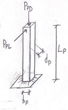
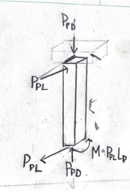
≔ pb = ⋅ ⋅ ρw ⎛ ⎜ ⎝ G ( (1+ ⋅G ( (0.009 .19))) ) ⎞ ⎟ ⎠ ⎛ ⎜ ⎝ 1+ .19 100 ⎞ ⎟ ⎠ 34.353 lb ft3 Density of Southern Pine (NDS Supplement 3.13) Loads: Name: Source: Figure: ≔ PPL + 0.2 kip ⋅ 0.05 kip ft L Transversal Live Point Load (AASHTO 13.8.2-1) = PPL 0.492 kip Vertical Dead Point Load (Weight of Railing) ≔ PPD = ⋅ wyD L 0.012 kip *Note: Transversal Live Load is applied at center of gravity of the upper longitudinal element ≔ LP = - hr ⋅ br .5 2.854 ft Applicablefactoredload governs with their respective timefactor, λ Non-Commercial Use Only
1.Posts: Assumed the the post acts like a cantilever (drawn below) Material: Dense Select Structural Southern Pine SectionProperties Property Source
3.5 in breadth NDS Supplement (Table 1B)
3.5 in depth NDS Supplement (Table 1B)
12.25 in2 Area NDS Supplement (Table 1B)
7.146 in3 Section Modulus, strong axis NDS Supplement (Table 1B)
7.146 in3 Section Modulus, weak axis NDS Supplement (Table 1B)
12.51 in4 Moment of Inertia, strong axis NDS Supplement (Table 1B)
12.51 in4 Moment of Inertia, weak axis NDS Supplement (Table 1B)
.55 Specific Gravity NDS Supplement (Table 4B)
2700 psi Bending design NDS Supplement (Table 4B)
2050 psi Comp parallel to grain NDS Supplement (Table 4B)
E 1900000 psi Modulus of Elasticity NDS Supplement (Table 4B)
690000 psi Min. Modulus of Elasticity NDS Supplement (Table 4B)
water
Applicablefactoredload governs with their respective timefactor, λ (Using NDS and ASCE, because there is bending and axial force) Case Factored Load (ASCE 7, 2.3) λ 1
Puy1 = 1.4⋅PPD 0.017 kip
Pux1 = 1.4⋅0 kip 0 lbf 2
Puy2 = 1.2 PPD 0.015 kip
Pux2 = 1.6⋅PPL 0.787 kip 3
Puy3 = 1⋅PPD 0.012 kip
Pux3 = 1.2⋅PPL 0.59 kip
λ1 .6
λ2 .8
λ3 .8
> Puy1 Puy2 Pu3 Will use case 2, since this has the largest transversal factored load. The vertical load is much smaller, thus it will not affect as much
> Pux2 Pux3 Pux1
Pux = Pux2 0.787 kip ReductionFactors used in this analysis. All from NDS, 2018
Puy = Puy2 0.015 kip Factor Name Source (NDS) Reasoning
Ci 1 Incising Factor 4.3.8 There are no incisions
CF 1 Size Factor 4.3.6 lumber is 4" thick but less than 8" wide
CL 1 Beam Stability Factor 3.3.3 Depth does not exceed breadth (d<b), since it is symmetrical
b = bp 3.5 in
d = dp 3.5 in
Ct 1 Temperature Factor 4.3.4 The structure will not experience sustained exposure of temps above 150F
CM 0.85 Wet Service Factor, bending Sup. 4B Since stairs outdoor, moisture will exceed 19% for extended periods of time
C
1 Repetitive Member Factor Sup. 4B posts are not in contact
Cfu 1 Flat Use Factor Sup. 4B depth and breadth CP Column stability factor 3.7.1 equation will be below CT Buckling Stiffness Factor 4.4-1 equation will be below
Stair Groups Railing
CEA R: GAH 12/05/22 9 of 14 ≔
h
⋅ br
Calculation
LP = -
r
.5 2.854 ft
≔
≔
Buckling
(NDS
Non-Commercial Use Only
≔
≔
≔
≔
≔
≔
≔
≔
≔
>
>
≔
≔
≔
≔
≔
≔
≔
≔
≔
r
Stiffness Factor CT
4.4.-1)
Buckling Stiffness Factor CT (NDS 4.4.-1)
≔
KM 1200 assuming wood is only partially seasoned
KT 0.59 visually graded lumber
Ke 2.1 Buckling length coeffcieicent (NDS, 2018 Table G1). Assume rotation fixed and translation free
le =
Ke LP 71.925 in Effective column length (3.7.1.2) (Effective length assumed same in both axis) = le d 20.55 (3.7.13) *Note slenderness ratio below 50, so acceptable = le b 20.55 (3.7.13) *Note slenderness ratio below 50, so acceptable Since le is less than 96", then
Fc '' = ⋅
Fc CM Ct CF Ci 2.4 0.9 λ2 3.011 ksi
KM le 1 in ⎞ ⎟ ⎠
⋅
CT = 1+
KT E psi
Emin CM Ct Ci CT ( (1.76) ) ( (0.85) ) 944.959 ksi Slenderness ratio found for buckling stability factor = le 71.925 in Calculate first Fc
Stair Groups Railing Calculation CEA R: GAH 12/05/22 10 of 14
≔
⋅ ⋅ ⋅ ⋅ ⋅ ⋅
≔
⋅ ⋅ ⋅ ⋅ ⋅
Inputs ≔
Assumptions p Non-Commercial Use Only
≔
≔
≔
⋅
≔
⎛ ⎜ ⎝
⋅
1.077 Column Stability Factor CP (NDS 3.7.1) c factor needed in calculation ≔c 0.8 (sawn lumber, NDS 3.7.1) reference compression design value parallel to grain multiplied by all applicable adjustment Fc '' factors except CP
Emin ' = ⋅
Fc = ⎛ ⎝0.822⋅Emin '⎞ ⎠ ⎛ ⎜ ⎝ le d ⎞ ⎟ ⎠ 2 1.839 ksi (NDS 3.7) Now can calculate C
Combinedbending
Since the loads are both tranverse and vertical to railing need to look at combined bending
Main equation
1 ME
2 ⎞
⎠
1 (NDS 3.9-1) = adjusted compression capacity P' =compressive force P =adjusted moment capacity (strong axis) M1 ' =bending moment (strong axis) M1 =ajusted moment capacity (weak axis) M2 ' =bending moment (weak axis) M2 = critical column buckling capacity(strong axis) PE1 =critical column buckling capacity(weak axis) PE2 =critical beam buckling capacity ME
First need moment capacity and buckling capacity, since the post is symmetrical, the moment capacity will be the same for both axis. The time factors were chosen previously in the load λ discussion section
Capaicity
Critical buckling capacity
First need to find slenderness ratio Distance between supports , will be the length of the post, which we will assume is a cantilever l
Effective length for bending, (NDS Table 3.3.3) le Since = lu d 9.786 > lu dE 7 assuming concentrated load at unsupported end
Stair Groups Railing Calculation CEA R: GAH 12/05/22 11 of 14
Now can calculate Cp ≔ CP =⎛ ⎜ ⎝ 1+ Fc Fc '' ⎞ ⎟ ⎠ 2 c 2⎛ ⎜ ⎜ ⎝ 1+ ⎛ ⎜ ⎝ Fc Fc '' ⎞ ⎟ ⎠ 2 ⎞ ⎟ ⎟ ⎠ 2 c ⎛ ⎜ ⎝ Fc Fc '' ⎞ ⎟ ⎠ c 0.699 (NDS 3.7.1)
+ + ⎛ ⎜ ⎝ P P' ⎞ ⎟ ⎠ M
M1
⎛ ⎜ ⎝ 1-⎛ ⎜ ⎝ P PE1 ⎞ ⎟ ⎠ ⎞ ⎟ ⎠
⎜
≤
1
'
M2 M2 ' ⎛ ⎜
⎝ - 1-⎛ ⎜ ⎝ P PE2 ⎞ ⎟ ⎠ ⎛ ⎜ ⎝ M
⎞ ⎟ ⎠
⎟ ⎟
≔
⋅ ⋅ ⋅ ⋅ ⋅ ⋅ ⋅ ⋅ ⋅ ⋅
≔
⋅
Moment
=λ λ2
Fb1 ' =
Fb CM Ct CL CF Cfu Ci Cr 2.54 0.85 λ2 3.964 ksi (NDS M4.3-1)
M1 ' =
Fb1 ' Syy 2.361 ⋅kip ft (NDS M3.3)
u ≔ lu = LP 2.854 ft
≔
Non-Commercial Use Only
leb = + 1.44⋅lu 3⋅d 4.985 ft Slenderness ratio (NDS 3.3-5) RB
Stair Groups Railing
CEA R: GAH 12/05/22 12 of 14 ≔ leb
lu
≔
⎛
⎛
⋅
Calculation
= + 1.44⋅
3⋅d 4.985 ft Slenderness ratio (NDS 3.3-5) RB
RB =
⎜ ⎝
⎝
leb d⎞ ⎠ b2 ⎞ ⎟ ⎠ 1 2 4.134 Since slenderness ratio does not exceed 50, it is acceptable. This is slenderness of edgeface
≔
⎛
≔
≔
⎛
≔
≔ M
' =
⋅
≔ F
=
⎛
≔ P
=
Adjusted
=λ λ2 ≔ Fc ' = ⋅ ⋅ ⋅ ⋅ ⋅ ⋅ ⋅ Fc CM Ct CF Ci CP
λ2 ⎛ ⎝
≔P' = ⋅ Fc '
Now
Compression ≔P = Puy 0.015
≔ fc = P
Bending-
≔M = ⋅ Pux LP 2.245 ⋅
≔ fb = M
Sxx
Non-Commercial Use Only
Critical buckling capacity Critical beam buckling capacity
FbE =
⎝1.2⋅Emin '⎞ ⎠ RB 2 66.346 ksi (NDS 3.9.2)
ME = ⋅ Syy FbE 39.509 ⋅kip ft (NDS M3.9) Crtical column buckling capacity
FcE1 = ⎛ ⎝0.822⋅Emin '⎞ ⎠
⎜ ⎝ le d ⎞ ⎟ ⎠ 2 1.839 ksi (NDS 3.7)
PE1 = ⋅ FcE1 A 22.532 kip (NDS M3.9) Since there is no strong or weak axis
2
M1 ' 2.361
kip ft
cE2
FcE1
⎝1.839⋅103 ⎞ ⎠ psi
E2
PE1 ⎛ ⎝2.253⋅104 ⎞ ⎠ lbf Calculate adjusted compressive capacity
Compressive Capacity
( (2.40) ) ( (0.90) )
1.889⋅103 ⎞ ⎠ psi (NDS M4.3-1)
A 23.138 kip (NDS M3.3)
calculate actual compressive force and bending moments
kip
A 1.215 psi
assume cantilver (NDS Design Aid-Figure 13)
kip ft
1
0.571 ksi
The equation for combined bending considers bending in both axis, since it is symmetrical will calculate main equation considering if moment is the strong or weak axis
Checkallcases forBendingandaxialcompression
If : =M M1 ≔ M1 =M 2.245 ⋅ft kip ≔ M2 ⋅ 0 kip ft ≔ fb1 = fb 0.571 ksi ≔ fb2 0 ksi = + + ⎛ ⎜ ⎝ P P' ⎞ ⎟ ⎠
2 M1 ⋅ M1 ' ⎛ ⎜ ⎝ 1-⎛ ⎜ ⎝ P PE1
⎞ ⎟ ⎠ ⎞ ⎟ ⎠
M2 ⋅ M2 ' ⎛ ⎜ ⎜ ⎝ - 1-⎛ ⎜ ⎝ P PE2
⎞ ⎟ ⎠ ⎛ ⎜ ⎝ M1 ME
0.952 (NDS 3.9-1)
⎞ ⎟ ⎠
2 ⎞ ⎟ ⎟ ⎠
This is less than1,thus passes case = + fc FcE2
⎛ ⎜ ⎝ fb1 FbE
⎞ ⎟ ⎠
2 7.35⋅10-4 (NDS 3.9-4)
This is less than1,thus passes case = FbE 66.346 ksi < fb1 FbE (NDS 3.9.2) = fb1 0.571 ksi sincethisistruepassescase < fb1 FbE If : =M M2 ≔ M2 =M 2.245 ⋅ft kip ≔ M1 ⋅ 0 kip ft ≔ fb2 = fb 0.571 ksi ≔ fb1 0 ksi =
Stair Groups Railing Calculation CEA 13 of 14
+ + ⎛ ⎜ ⎝ P P' ⎞ ⎟ ⎠ 2 M1 ⋅ M1 ' ⎛ ⎜ ⎝ 1-⎛ ⎜ ⎝ P
⎞
⎞
⋅
Non-Commercial Use Only
PE1
⎟ ⎠
⎟ ⎠ M2
M2 ' ⎛ ⎜ ⎜ ⎝ - 1-⎛ ⎜ ⎝ P PE2 ⎞ ⎟ ⎠ ⎛ ⎜ ⎝ M1 ME ⎞ ⎟ ⎠ 2 ⎞ ⎟ ⎟ ⎠ 0.952 (NDS 3.9-1) This is less than1,thus passes case = + fc FcE2 ⎛ ⎜ ⎝ fb1 FbE ⎞ ⎟ ⎠ 2 6.608⋅10-4 (NDS 3.9-4) This is less than1,thus passes case
= FbE 66.346 ksi
= fb1 0 ksi
< fb1 FbE (NDS 3.9.2)
sincethisistruepassescase < fb1 FbE
Other cases to consider
= FcE1 1.839 ksi
< fc FcE1
= fc 0.001 ksi (NDS 3.9.2)
sincethisistruepassescase < fc FcE1
= FcE2 1.839 ksi
= fc 0.001 ksi
< fc FcE2 (NDS 3.9.2)
sincethisistruepassescase < fc FcE2
Memberpasses allcases,thedimensions chosenareappropriate
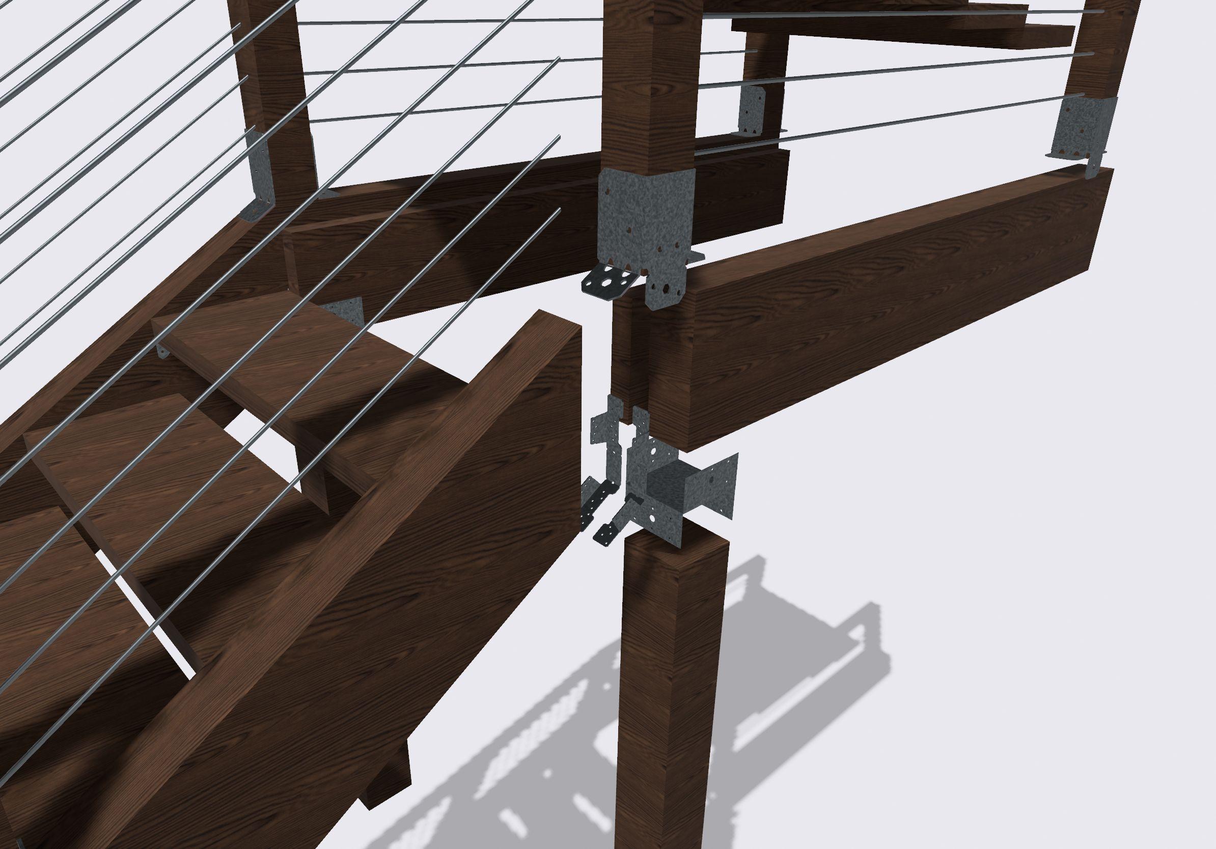
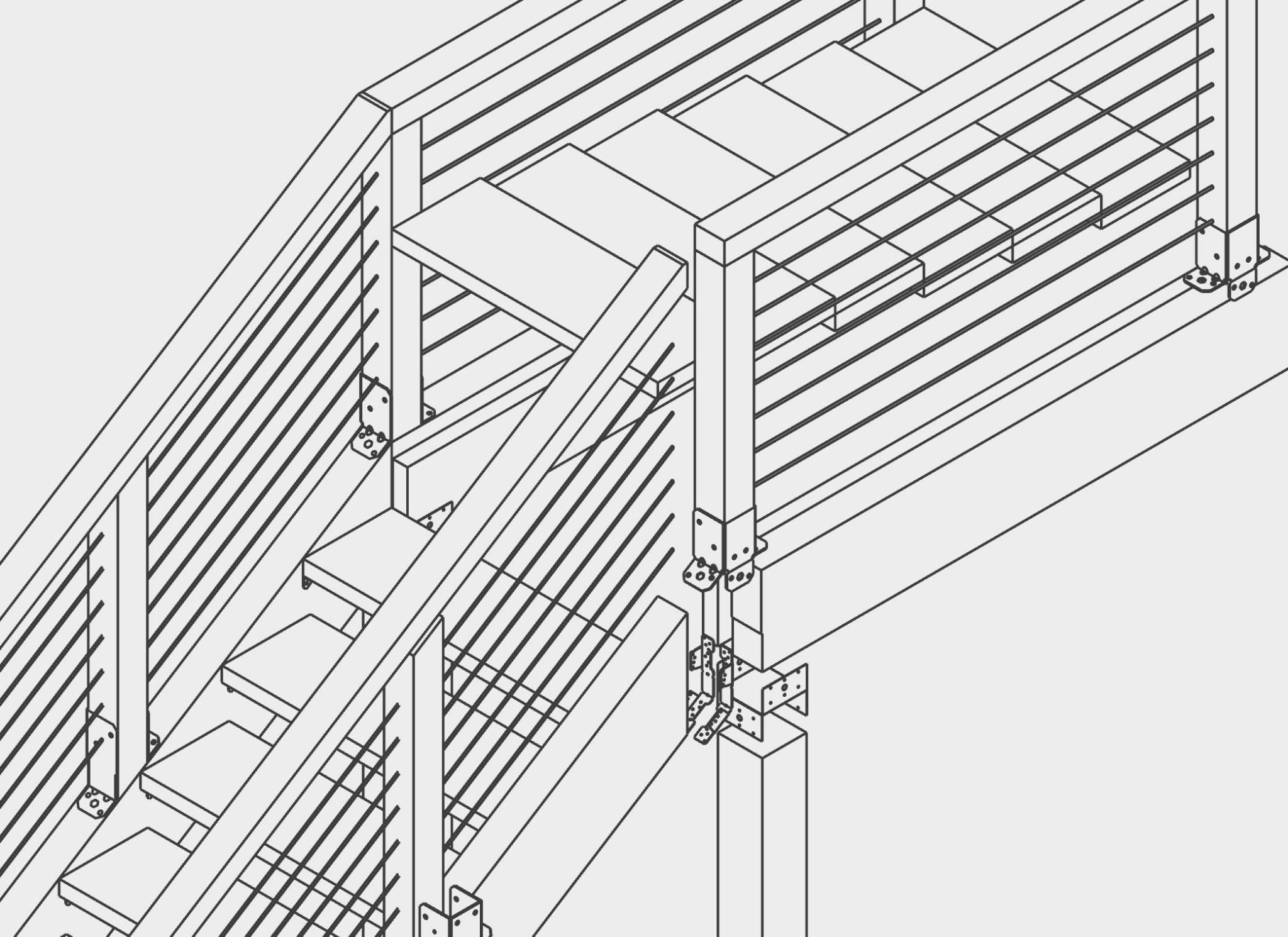
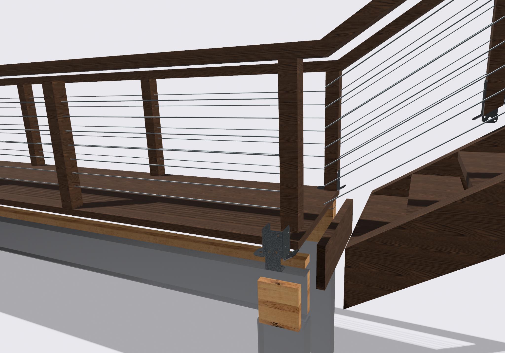
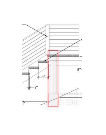
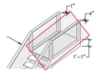
The posts will then be connected to the stringer using the following connection. This connection will need to be able to handle the reactions caused by the loads.
Stair Groups Railing Calculation CEA R: GAH 12/05/22 14 of 14
Non-Commercial Use Only
Team Stairs – Geotechnical Engineering Calculations
Soil Assumptions:
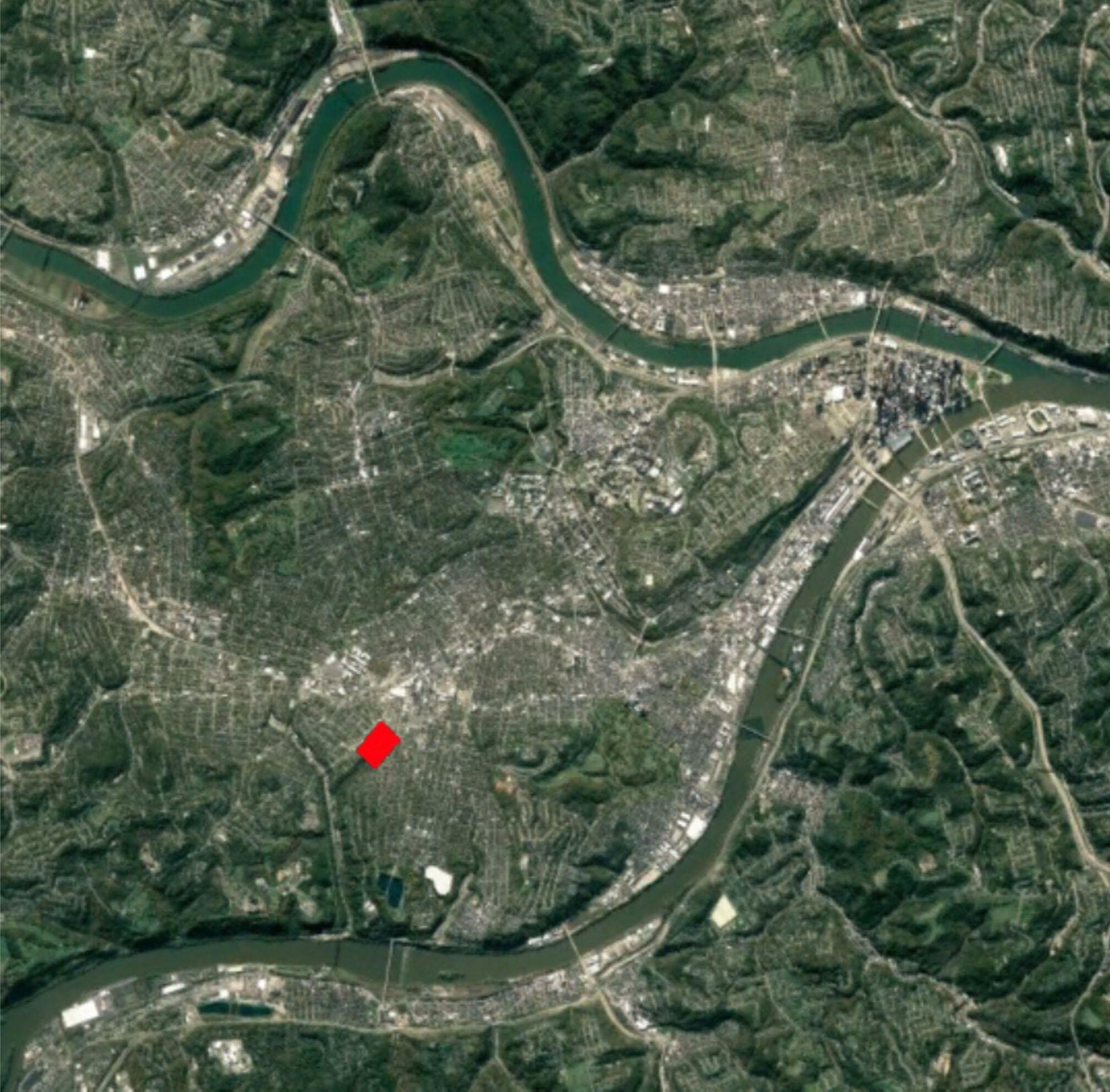
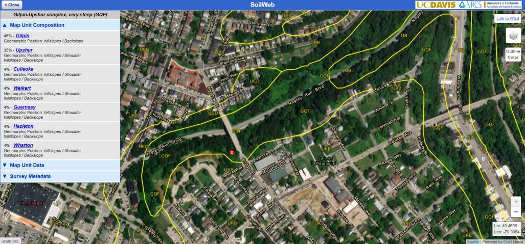
UC Davis SoilWeb classifies the soil on-site as Gilpin-Upshur complex.
Figure 1. Soil Classification for Site (UC Davis).
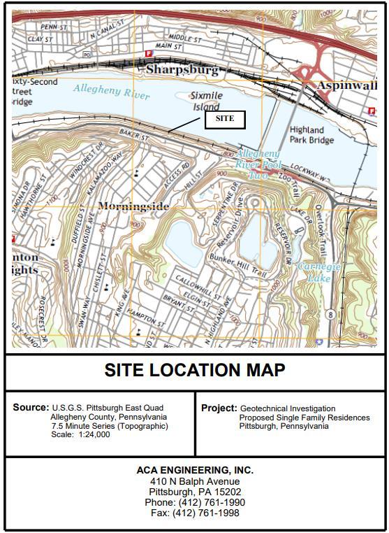
In order to find parameters for the soil on-site, without the ability to take borings, I searched for a geotechnical report on a nearby site with the same classified soil. I was able to find a geotech report for, “Proposed Single Family Residences”, which was prepared by ACA Engineering for MJS Group Ventures in 2019. This site was located at Butler Street, only 1.5 miles from our site, and had the same classified soil of Gilpin-Upshur complex. For all the reasons above, we felt this source was applicable to use for our site and was utilized to determine soil properties.
Figure 2. Site Location of Geotechnical Report, Located 1.5 Miles North From Negley Run (ACA Engineering 2019).
Team Stairs 12-401 Geotech Calcs 11-1-22 1/9
Table 1. Existing Soil Properties for Similar Site and Soil (ACA Engineering 2019).
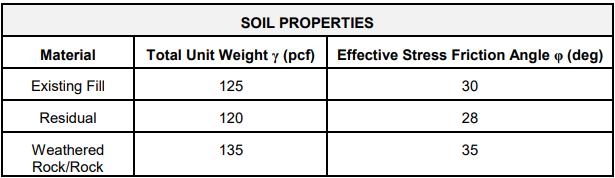
Using the soil properties above, I assumed the soil to have similar properties as the residual soil found at the Butler Street proposed project. The effective friction angle was reduced to 12 degrees to account for poor soil, per the recommendations of Dr. Jim. This is logical since the soil is more cohesive than granular due to the large presence of clay. ����������������ℎ��������������
Unfortunately, the tests ran for this geotechnical report did not result in a determination of the cohesion of the clay in this silty clayey soil. This was estimated by using Table 2 below since SPT values were known for the silty clayey layer of the soil on-site. These SPT values averaged ~10 for this layer, as seen in the ACA geotechnical boring logs. The soil on-site classifies as an intermediate soil due to the presence of both silt and clay. Additionally, the water table was stated as being, “more than 80 inches below ground surface” (Negley Run Watershed Task Force 2021), thus not making it a worry when designing foundations since the footing thickness doesn’t reach.
Table 2. Estimates for Cohesion Using SPT Values (Raffek 2016). ����ℎ����������=��′ =100������
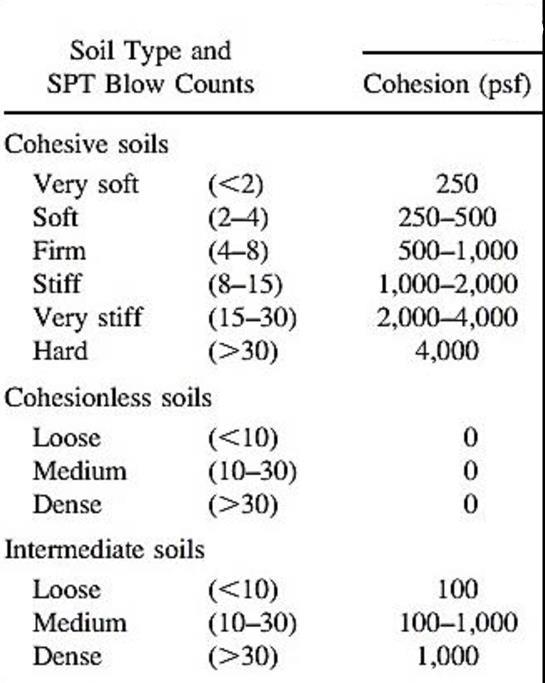
Team Stairs 12-401 Geotech Calcs 11-1-22 2/9
=�� =120������ �������������������������������������������� =��′ =12°
Spread
Footings:
Our staircase will sit on square concrete footings which will support wooden and steel columns attached to the stairs. These footings will support portions of the bridges as well. A concrete weight of 150 pcf and compressive strength of 3,500 psi is assumed.
load column concrete footing
Figure 3. Labeled Spread Footing.
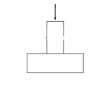
Team Stairs 12-401 Geotech Calcs 11-1-22 3/9
Demand: The demand determined for the foundations was found using the uniform loads for stairways and decking from ASCE 7 and the American Wood Council. The loads on the columns to be transferred to the footings were then calculated in the stair and bridge calculations. ������������������������������������ =0.225������ ������������������������������������ =0139������ �������������������������������������� =����������������+���������������� =0.364������(������������������������������������������) ���������������������������������������� =����������������+���������������� =4.893������(��������������������������������������������) In order to calculate the equivalent surcharges for these loads, I divided the loads by the area of the footings. I found this footing dimension using an iterative process of calculating the bearing capacity and estimating the square footing dimensions. ������������������������������=1����∗1����=1����2 ��������������������������������=2����∗2����=4����2 ������������������������������������������������ℎ�������� =���������� = ������������������ ���������������������� = 0.364������ 1����2 =364������ ��������������������������������������������������ℎ�������� =������������ = ������������������ ���������������������� = 4893������ 4����2 =1223������
Bearing Capacity using Terzaghi’s Equation: Figure 4. Bearing Capacity Formula & Table for Square Footing (Das 2017).
the capacity factors using effective friction angle determined in soil assumptions. A φ’ of 12° corresponds to the following capacity factors.
then must assume a width of our foundation to ensure proper capacity. The American Wood Council recommends a square footing size of 13”x13” for our beam and joist spans, and to achieve a safe bearing capacity. I chose to start with 12”x12” and iterate the design until a safe factor of safety is achieved. I also considered the dimensions of the columns which are approximately 6”x6”.
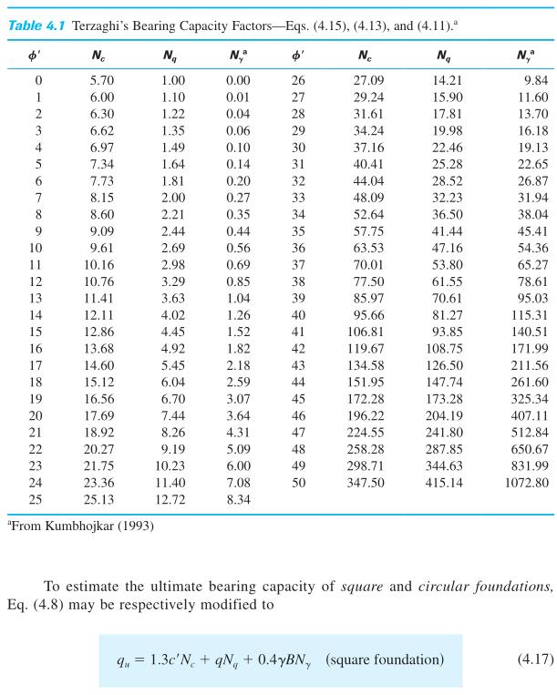
Team Stairs 12-401 Geotech Calcs 11-1-22 4/9
����
����
����
Soil
����������������ℎ�������������� =�� =120������ �������������������������������������������� =��′ =12° ����ℎ����������=��′ =100������
Determining
=10.76
=329
=085
parameters assumed from assumptions above are as follows.
We
=������
=��������ℎ������������������=��������ℎ���������������������� =44����=3.67����
=12���� =1����
=12���� =1����
=���� =1.3��′���� +������ +0.4��������
=13(100������)(1076)+(120������)(367����)(329)+04(120������)(1����)(085)
���������� =2889������
������������ =1.3(100������)(10.76)+(120������)(3.67����)(3.29)+0.4(120������)(2����)(0.85)
=2929������ The American Wood Council suggests that the soil that these square foundations lay on should have a bearing capacity of 3000 psf on the higher end of their suggested range of soils. This aligns with the calculated values above.
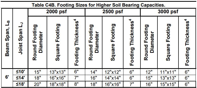
����
������������������ = 2889������ 364������ =79
���� �������������������� = 2929������ 1223������ =24 A factor of safety of 7.9 and 2.4 will be adequate in the design of these foundations. This allows for any errors in our assumed soil assumptions as well. The wood has a large factor of safety due to the area of the column needing to safely fit on the foundation.
Estimated Footing Size using DCA6 – American Wood Council:
The footing size can also be estimated using DCA6 which can confirm that our design calculations above are correct.
Table 4. Estimated Square Footings Sizes (American Wood Council 2015).
Team Stairs 12-401 Geotech Calcs 11-1-22 5/9
��
����
����������������ℎ������������������������������������=��
������������������ℎ������������������������������������=��
������������������������������
������������
��
��
��������������
������������������������������������������������������������������������������=
��
��������������������������������������������������������������������������������=
Table 4 above shows to achieve a bearing capacity of 3000 psf with a joist span of ~14’ and beam span of 6’, the footing size should be approximately 13”x13”. This corresponds with our chosen footing sizes. The American Wood Council suggests that the soil that these square foundations lay on should have a bearing capacity of 3000 psf on the higher end of their suggested range of soils. This corresponds to our calculated values.
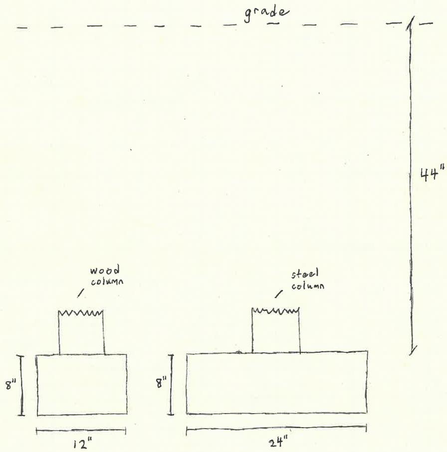
Other Footing Dimensions:
The thickness of our footing can be estimated using Table 4 from the American Wood Council. They recommend a footing thickness of 6” for our existing loads and dimensions. We assumed all of this recommend footing thickness would be below grade. The footings are to be installed below the frost depth after excavation. This excavated area will then be backfilled with existing soil. The Das textbook suggests a minimum footing thickness of 8 inches for footings such as the one we are designing. We chose to go with this number, and it was smaller than our footing widths which is required as well. ����������������ℎ��������������=8����
Figure 5 below shows all of our footing dimensions for clarification.
Figure 5. Square Footing Dimensions.
Team Stairs 12-401 Geotech Calcs 11-1-22 6/9
Settlement: In order to calculate the settlement of my foundations I only looked at primary consolidation due to a lack of known information. I assumed that the existing soil could be classified as a normally consolidated clay since the soil is a silty clay and has most likely not been loaded in the past. Additionally, settlement is most likely not a concern due to the small loads being applied to the foundations.
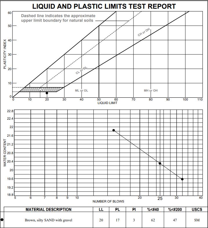
Team Stairs 12-401 Geotech Calcs 11-1-22 7/9
�������������������������������������������������������������������������������������� =���� = ������ 1+��0log(��0 ′ +∆��′ ��0 ′ )
���������������������� =���� =20 �������������������������������� =���� =0.009(���� 10)=0.009(20
��ℎ������������������������������������ =��
The compression index can be determined by using the following equation from Skempton (1944). The liquid limit for the clay was given in the ACA Engineering report. This section of the report is shown below in Figure 6. Figure 6. Liquid & Plastic Limit Tests from Butler St Project (ACA Engineering 2019).
10)=0.09 The thickness of the silty clay layer is assumed to be continuous from the ground surface to the bedrock which typically ranges from approximately 20 to 40 inches below ground surface (Negley Run Watershed Task Force 2021). I decided to take the average of these values to estimate the thickness.
=30����=2.5����
The in situ void ratio can be determined using this estimated compression index. The compression index for inorganic cohesive soils, silts, silty clays, and clays equation using void ratio was used from Das.
This settlement of 1.2” is generally within the standard tolerance of 1” of settlement in foundation construction. We would hope that the bedrock located directly below the clay layer would help reduce this settlement.
Soil Reinforcement:
The Implementation Framework outlines evidence of landslide activity on the site and near the existing stairs. They specifically highlight slopes steeper than 1.5H:1V as being landslide prone and should be investigated to help mitigate this danger. In their report they write these slopes, “… have been labeled as slopes with moderate to severe susceptibility to landsliding” (Negley Run Watershed Task Force 2021). We highlighted these landslide prone areas in Figure 7 below.
Figure 7. Hatched Landslide Prone Areas Near Stairs.
To prove these slopes as being unstable and needing additional reinforcement for landslide protection, I calculated the factor of safety of the homogeneous slope. To perform these calculations, I assumed the soil to be homogenous and used the same assumed soil parameters from the previous sections. I used Taylor’s friction circle method of slope stability and the
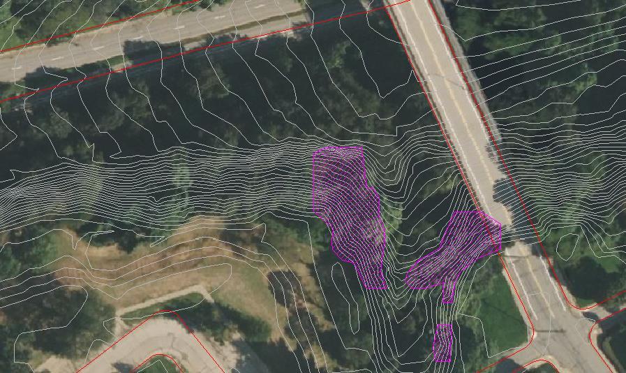
Team Stairs 12-401 Geotech Calcs 11-1-22 8/9
������������������������������=��
����������������������������������������������������������������������������������=��0 ′ =���� =120������∗2.5����=300������ ���������������������������������������������������� =∆��′ =��������ℎ������������������������=�� =1223������ ���������������������������������� =���� = 0.09∗2.5���� 1+0.57 log(300������+1223������ 300������ )=0101����=12����
0 = ���� 030 +0.27= 009 030 +0.27=0.57
results from Singh (1970) to calculate the factor of safety. The slope stability number is determined as follows below. Additionally, the average height of the slope was calculated using the contour lines from Figure 7, where the top and bottom of the landslide prone slope was at the top and bottom of the two large, hatched areas.
ℎ������ℎ�������������������������������������������� =�� = (890′ 850′)+(900′ 870′) 2 =35���� ����������������������������������������=�� = �� ′ ���� = 100������ 120������∗35���� =0.024
Figure 7. Plot of Stability Number Against FS Based on Singh, 1970 (Das 2017).
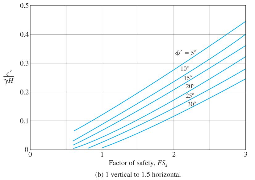
��������������������������������������≈0.8
This small slope factor of safety shows that landslides are a real concern and should be mitigated in a non-invasive and cost-effective manner. Our research showed that a good solution would be the installation of SlopeGrid in these landslide prone areas. SlopeGrid helps reinforce steep slopes by reducing soil sliding and migration, reducing erosion, which is a major cause of landslides, and by minimizing impacts on the slope from water. Additionally, this geotextile fabric is laid on top of the slope surface which doesn’t disrupt the slope. SlopeGrid did not have any definitive engineering calculations to back up their claims. Our research showed that an optimal solution would have anchors that extend beyond the slope failure surface. The longest earth anchor we were able to find in our research was 96”. These would extend through the failure surface in most areas of the slope. ��������ℎ������ℎ��������������ℎ=96����
Team Stairs 12-401 Geotech Calcs 11-1-22 9/9
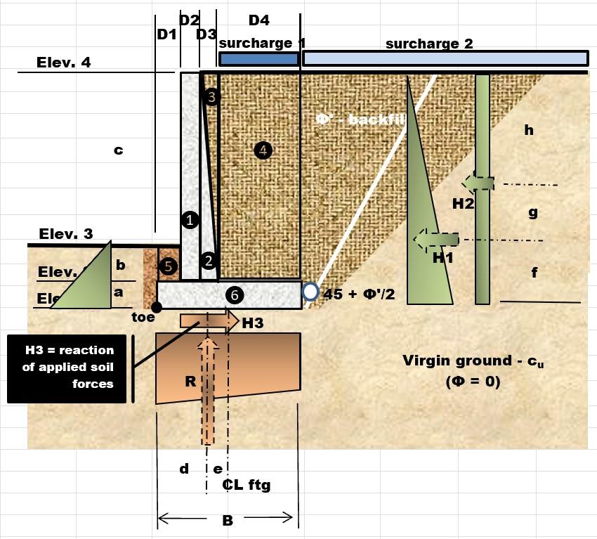
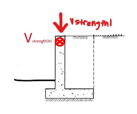
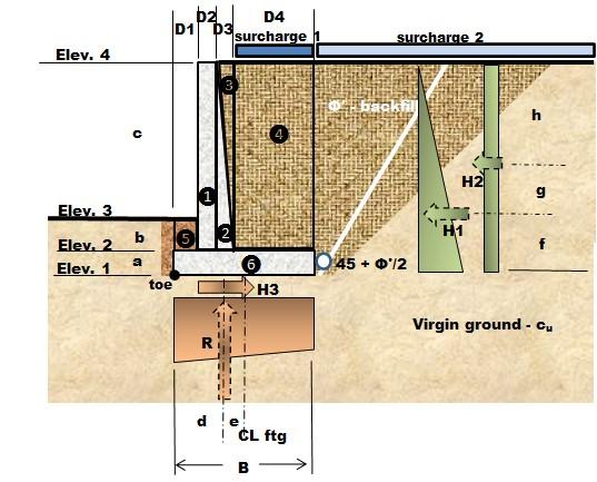
Stair Group Bridge Abutment Calculations GAH, R:CEA,OSM 11/04/2022 1 of 5 DesignandCheckBridgeAbutmentBearingCapacityandCapacityAgainst SlidingandOverturning Generic Retaining Wall with Passive Pressure Shape of Retaining Wall To Analyze acts into the page, so is not Vstrength3H considered in this calculation RetainingWallPropertiesandDimensions (dimensions shown in figure) ≔l 6.5⋅ft length of wall ≔ VStrength1 4.893⋅kip Maximum Shear Force from One Girder from Bridge Calculations ≔V = 2⋅VStrength1 l 1.506 klf Shear Force from Both Girders per foot ≔ D1 6⋅ft ≔ D2 1.50⋅ft ≔ D3 1.5⋅ft location shown in diagram ≔ D4 10⋅ft ≔a 1.5⋅ft ≔b 3⋅ft ≔c 4⋅ft Figure: ≔f = + +a b c 3 2.833 ft ≔g = + +a b c 6 1.417 ft ≔h = + +a b c 2 4.25 ft Non-Commercial Use Only
Df = +a b 4.5 ft height for passive pressure
ratio = w hwall 2.235 ratio of base to design height of wall
B = + + + D1 D2 D3 D4 19 ft heel length
SoilProperties - Based on spread footing calculations. Refer to those calculations for assumptions
ϕ' 12⋅
effective internal friction angle for chosen backfill
0.10⋅ksf virgin ground cohesion Given that , the Meyerhof's Bearing Capacity Factors (Das 2017) are
N
0.85
0.15⋅ kip ft3 unit weight of concrete
δ' 22⋅° effective external friction angle for concrete
AASHTOLRFDFactors
R 0.167 resultant location factor AASHTO 11.6.3.3
0.85 sliding factor AASHTO 10.6.3.4 & 10.5.5.2.2
b 0.50 bearing factor AASHTO 10.6.3.3 & 10.5.5.2.2 There is no LRFD Factor for overturning, so the calculation will be done without LRFD factors AASHTO Strength 1 Assumed
DCb 1.25
2 of 5 ≔
≔
≔
≔
Stair Group Bridge Abutment Calculations GAH, R:CEA,OSM 11/04/2022
h = + +a b c 2 4.25 ft
hwall = + +a b c 8.5 ft wall height
w = + + + D1 D2 D3 D4 19 ft footing width
≔
≔
≔
≔
≔
≔
≔
≔
°
γs 0.12⋅ kip ft3 backfill unit weight
cu
≔ϕ' 12⋅°
Nc 10.8
Nq 3.29
γ
≔ γc
≔
≔
≔
≔
≔
≔
≔
≔
≔
τ
≔
≔
≔
τ
≔
Horizontal
≔ KA = ⎛ ⎜ ⎝ tan⎛ ⎜ ⎝ 0.785- ϕ' 2 ⎞ ⎟ ⎠ ⎞ ⎟ ⎠ 2
≔ KP = ⎛ ⎜ ⎝ tan⎛ ⎜ ⎝ 0.785+ ϕ' 2 ⎞ ⎟ ⎠ ⎞ ⎟ ⎠ 2 1.522
≔ PA = ⋅ ⋅ KA γs ( ( + +f g h) ) 2 2
≔ PP = ⋅ ⋅ KP γs ( ( +a b) ) 2 2 1.85 klf Non-Commercial Use Only
φ
φτ
φ
DCR 1.25 ≔ DCτ 0.90
EVR 1.35 ≔ EVτ 1.00 ≔ EVb 1.35
ESR 1.50
ES
0.75
ESb 1.50
EHR 1.50
EH
1.50
EHb 1.50 ForceEffectsBasedonServiceLoads
Forces - Service Loads
0.655 active earth pressure coefficient
passive earth pressure coefficient
2.838 klf active earth pressure
Vertical Forces & Moment Summation About Toe - Service Loads
W1 = + ⋅ ⋅ ( ( +b c) ) D2 γc V 3.081 klf weight of stem (element 1) and weight from bridge girder
A1 = + D1 D2 2 6.75 ft distance from toe to location where W1 acts
W2 = ⋅ ⋅ ⋅ 1 2 ( ( +b c) ) D3 γc 0.788 klf weight of triangle part of stem (element 2)
A2 = + + D1 D2 D3 3 8 ft distance from toe to location where W2 acts
W3 = ⋅ ⋅ ⋅ 1 2 ( ( +b c) ) D3 γs 0.63 klf weight of triangle area of soil (element 3) ≔ A3 = + + D1 D2 2⋅D3 3 8.5 ft distance from toe to location where W3 acts
W4 = ⋅ ⋅ ( ( +b c) ) D4 γs 8.4 klf weight of soil on top of heel on right side of stem (element 4)
toe to location where W4 acts
of soil on top of heel on left side of stem (element 5)
from toe to location where W5 acts
Stair Group Bridge Abutment Calculations GAH, R:CEA,OSM 11/04/2022 3 of 5
≔ PP = ⋅ ⋅ KP γs ( ( +a b) ) 2 2 1.85 klf passive earth pressure
≔
≔
≔
≔
≔
≔
≔
≔ A4 = + + + D1 D2 D3 D4 2 14 ft distance from
≔ W5 = ⋅ ⋅b D1 γs 2.16 klf weight
≔ A5 = D1 2 3 ft distance
≔ W6 = ⋅ ⋅a ⎛ ⎝ + + + D1 D2 D3 D4⎞ ⎠ γc 4.275 klf weight of heel (element 6) ≔ A6 = + + + D1 D2 D3 D4 2 9.5 ft distance from toe to location where W6 acts = PA 2.838 klf ≔ AA =f 2.833 ft = PP 1.85 klf ≔ AP = ( ( +a b) ) 3 1.5 ft ≔R = + + + + + W1 W2 W3 W4 W5 W6 19.333 klf Moment Summation About Toe - Resisting Moment ≔ M1 = ⋅ W1 A1 20.794 ⋅kip ft ft moment from element 1 ≔ M2 = ⋅ W2 A2 6.3 ⋅kip ft ft moment from element 2 ≔ M3 = ⋅ W3 A3 5.355 ⋅kip ft ft moment from element 3 ≔ M4 = ⋅ W4 A4 117.6 ⋅kip ft ft moment from element 4
M5 = ⋅ W5 A5 6.48 ⋅kip ft ft moment from element 5 Non-Commercial Use Only
Stair Group Bridge Abutment Calculations GAH, R:CEA,OSM 11/04/2022 4 of 5 ≔ M4 = ⋅ W4 A4 117.6 ⋅kip ft ft ≔ M5 = ⋅ W5 A5 6.48 ⋅kip ft ft
≔ M6 = ⋅ W6 A6
⋅
ft ft
≔ MP = ⋅ PP AP
⋅
ft ft
≔ MR = + + + + + + M1 M2 M3 M4 M5 M6 MP
⋅
Toe -
≔ MA = ⋅ ⋅ PA AA -1 -8.041 ⋅kip ft ft Resultant Location Recompute force effects based on LRFD Load Factors x weights/moments for individual elements ≔ RR_LRFD = + + ⋅ ⎛ ⎝ + + W1 W2 W6⎞ ⎠ DCR ⋅ ⎛ ⎝ + + W3 W4 W5⎞ ⎠ EVR ⋅ PP EHR 28.06 klf ≔ MR_LRFD = + + ⋅ ⎛ ⎝ + +
2 M6⎞ ⎠ DCR ⋅ ⎛ ⎝ + +
4
5⎞ ⎠ EVR ⋅ MP EHR
⋅
≔
= ⋅
≔
⋅ ⋅
≔
≔
≔
≔
≔ RS_LRFD = + + ⋅ ⎛ ⎝ + + W
W2 W6⎞ ⎠ DCτ ⋅ ⎛ ⎝ + +
5⎞ ⎠ EVτ ⋅ PP
τ
≥ ⋅ ⋅ φτ R tanδ' P
≔ FS
= ⋅ ⋅ φτ R tan(
P
≔ RB_LRFD = + + ⋅ ⎛ ⎝ + +
2 W6⎞ ⎠ DCb ⋅ ⎛ ⎝ +
⎞ ⎠
⋅
Non-Commercial Use Only
moment from element 5
40.613
kip
moment from element 6
2.775
kip
moment from passive pressure
199.916
kip ft ft resisting moment Moment Summation About
Overturning Moment
M1 M
M3 M
M
263.532
kip ft ft
PA_LRFD
PA EHR 4.257 klf
MO_LRFD =
PA_LRFD AA -1 -12.062 ⋅kip ft ft
Mtotal = + MR_LRFD MO_LRFD 251.47 ⋅kip ft ft
d = Mtotal RR_LRFD 8.962 ft distance from toe to resultant location
e =B 2 d 0.538 ft resultant eccentricity check if resultant lies in middle two thirds of heel
RB = ⋅ φR B 3.173 ft Since ≤ 3.173⋅ft d theresultantlocationis good Sliding Factor of Safety
1
W3 W4 W
EH
21.293 klf check if
A_LRFD 1.0
S
(δ') )
A_LRFD 1.56 Since thisisacceptable ≥ FSS 1 Bearing Pressures
W1 W
+ W3 W4 W5
EVb
PP EHb 28.06 klf
Demand to Capactiy (D/C) Ratios There is no LRFD for overturning so it will not be included in this section Check that all ratios are less than 1 (a reverse Factor of Safety calculation) D/C for R Location D/C for Bearing
Stair Group Bridge Abutment Calculations GAH, R:CEA,OSM 11/04/2022 5 of 5 ≔ RB_LRFD = + + ⋅ ⎛ ⎝ + + W1 W2 W6⎞ ⎠ DCb ⋅ ⎛ ⎝ + + W3 W4 W5⎞ ⎠ EVb ⋅ PP EHb 28.06
≔B' = -B 2⋅e
≔ q
=
⋅
= qu + ⋅ ⋅ Fci cu Nc ⋅ ⋅ Fqi ⎛ ⎝ ⋅ γs Df⎞ ⎠ Nq ≔β = atan ⎛ ⎜ ⎝ PA RB_LRFD ⎞ ⎟ ⎠
≔ Fci = ( (
) ) 2
≔ Fqi =
) 2
≔ qu = + ⋅ ⋅ Fci cu Nc ⋅ ⋅ Fqi ⎛ ⎝ ⋅ γs D
⎞ ⎠
⋅
≔
⋅
klf Compute Elastic Pressures; Average Bearing Pressure X FS to Ultimate Pressure
17.924 ft effective footing width
ave_eff
R B' 1.079
ft ksf ft average effective stress
0.101
1-β
0.809
( (1-β)
0.809
f
Nq 2.31
ft ksf ft
FSb =
φb qu qave_eff 1.071 Overturning Check no LRFD used for overturning = MR 199.916 ⋅kip ft ft resisting moment = MA -8.041 ⋅kip ft ft overturning moment from active earth pressure =R 19.333 ⋅ 1 ft kip vertical reaction resisting weight of elements (overturning) =d 8.962 ft distance to resultant from toe ≔ MO = + MA ⋅R d 165.219 ⋅kip ft ft > MR MO sotheabutmentwillnotoverturn
≔
≔
Non-Commercial Use Only
D'CR = RB d 0.354 below1,sogood ≔ D'Cb = 1 FSb 0.934 below1,sogood D/C for Sliding
D'CS = 1 FSS 0.641 below1,sogood
Stringers
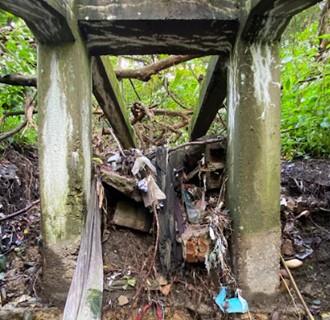
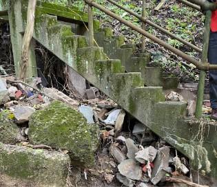
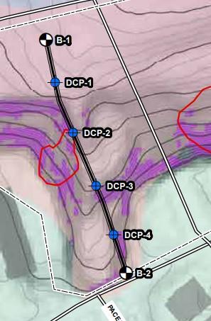
Stair Group Detailed Cost Estimate CEA/ETP R:CEA 12/06/22 1 of 11
Thisdocumentcontainsmaterialtakeoffusedforcostestimateandthelifecycleassesment. I.MATERIALTAKEOFF-These take-offs will be inputted into RS means to obtain cost information. Clearing and grubbing is being estimated by Stream Team. 1.ConcreteStairsDemolition (NRTWF, 2021)
≔
≔
≔
≔
= ⋅ ⋅
≔
≔
≔t =
≔
=
≔ Vc = ⋅ ⋅ ⋅ ⋅N
Using aerial map the length of stairs, L is
L 311 ft Assume thickness of stringer is a foot and a depth is 1.5ft
b 1.5 ft
t 1 ft Volume of Stringers is
VS
b t L 466.5 ft3 Column Assume columns are at point of boring locations (ex. DCP-1) and there is 4 at each location
N 4
L 6 ft Assume columns are squares, with following dimensions
b 1.5 ft
b
t 1.5 ft
t b L 4 216 ft3
≔
14
≔
≔
≔ VF = ⋅ ⋅ ⋅ ⋅N 4 t b L 43.556 ft3
≔V = + + Vc VF VS 26.891 yd3
≔
2.Decking
Non-Commercial Use Only
Footing Assume footing is 14inx14inx24in
t
in
b 14 in
L 2 ft
Totalvolume
Round up, to account for uncertainty and the fact that I did not include volume of the few steps that are still attached to stairs
Vround 30 yd3
2x12
2.Decking2x12 2x12 boards will be used for stairs and decking of bridges. All boards will be 3ft long. RS means only has 2x6 so I used that in cost estimating
3 ft width of bridge and stairs
11.25 in nom. width board
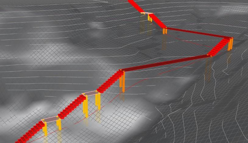
BridgeDecking:
Top Bridge
45 ft length bridge Total number of boards top bridge
Lower Bridge
37 ft length bridge Total number of boards bottom bridge
AboveGroundSteps: Top Stairs (shown in picture above)
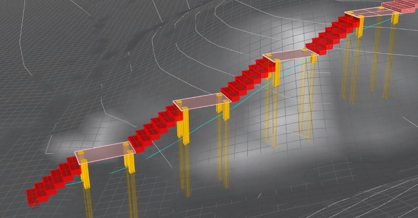
12 number of 3ft treads in top stairs
ft 6 number of flights of stairs
Total number of top stairs
Lower Stairs
6 number of 3ft treads in top stairs
fl 4 number of flights of stairs
Total number of lower stairs
Landing
7 number of landings
6 ft length of landings
Total number of boards landings
Total square feet of decking stairs Total Number of Boards Non-Commercial Use Only
Stair Group
CEA/ETP R:CEA 12/06/22 2 of 11 ≔ Vround 30 yd3
Detailed Cost Estimate
≔w
≔ nw
≔ lBT
≔ Nbt = lBT nw
48
≔ lBL
≔ Nbl = lBL nw
≔
39.467
Nbl 40
≔ nt
≔ n
≔
= ⋅ nt
Nst
nft 72
≔ nt
≔ n
≔ Nsl = ⋅ nt n
fl 0.174
≔ nL
≔L
≔
L nw
NL = nL
44.8
Total square feet of decking stairs
⎝ + + Nsl Nsl NL⎞ ⎠ w nw 261 ft2
Round up, square feet ≔ DL 270 ft2
Total Number of Boards = ⋅ ⋅
NBT = + + ↲ + + Nsl Nsl NL Nbl Nbt
181
Total square feet of decking bridge = ⋅ ⋅ ⎛ ⎝ + Nbl Nbt⎞ ⎠ w nw 247.5 ft2
Round up, square feet ≔ DL 250 ft2
3.ColumnsWood
There is 9 sets of columns, 7 of these sets will be made of wood, each of the wooden sets has 4 columns. The wooden columns are 6" by 6"
Total amount of wood columns ≔ NCol.W 28
Sum of the height of columns obtained from drawings (rounded to nearest inch). RS mean calculates cost by LF ≔LF = + + + + ↲ + + + + + + + + + + + + ↲ + + + + + + + + + + + 38 in 39 in 29 in 31 in 52 in 52 in 26 in 25 in 37 in 34 in 10 in 2 in 30 in 20 in 15 in 6 in 58 in 50 in 48 in 39 in 99 in 88 in 75 in 65 in 52 in 44 in 11 in 6 in
90 ft
4.ColumnsSteel
There is two columns on the top bridge, since the start of the bridge is in contact with the land. The bottom bridge has 4 columns. Assume the columns are W12x50, which is the lightest column W12 in RS means
Total amount of steel columns ≔ NCol.S 6
LF = + + + + + 83 in 68 in 52 in 48 in 23 in 23 in 25 ft
5.Stringers-Wood
Stringers for stairs will be 4"x12", but RS means only has 2"x12" so estimate will be based on that
Top Stairs
Lower Stairs
Landings
Stair Group Detailed
CEA/ETP R:CEA 12/06/22 3 of 11 ≔ NL = nL L nw
Cost Estimate
44.8
⎛
≔
≔
≔ lst
≔ nstS = ⋅ n
11 ft (length of stairs from drawings)
ft 2 12 (total stringers top stairs)
≔ lsL
≔ nflS = ⋅ nfl 2
7 ft (length of stairs in drawing)
8 (total stringers low stairs)
≔ lL =L
≔ nLS = ⋅ nL 2 14
6 ft (length of landing)
(total stringers landing) Total linear feet Round up Non-Commercial Use Only
6.Beams-Steel
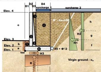
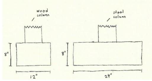
Stair Group Detailed Cost Estimate CEA/ETP R:CEA 12/06/22 4 of 11 ≔ nLS = ⋅ nL 2 14
linear feet
≔LF = 2 ⎛ ⎝ + + ⋅ lst nft ⋅ lsL nfl ⋅ lL nL⎞ ⎠ 272 ft ≔LF
Total
Round up
280 ft
≔LF = 2 ⎛ ⎝ + lBT lBL⎞ ⎠
Round
≔LF
Dimensions ≔w 12
≔
≔
Total
Round
≔ VFW = ⋅ ⋅ ⋅w b h ⎛ ⎝NCol.W⎞ ⎠ 0.691
3 ≔ VFW
≔w
≔
≔
≔ VFS = ⋅ ⋅ ⋅w b h ⎛ ⎝NCol.S⎞ ⎠ 0.593 yd3 ≔ VFS
Total
≔ VF = + VFW VFS 2 yd3 There
retaining
≔ wba 19 ft footing width ≔ lba 6.5 ft footing length ≔ hba 8.5 ft footing height ≔ Vba = ⋅ ⋅ wba lba hba 38.88 yd3 round up = Vba 39 yd3 8.In-groundstairs Non-Commercial Use Only
Total linear feet, use length of bridges and the fact that there is 2 beams bridge
164 ft
up. The beams are assumed to be W12x16 for calculations
170 ft 7.Foundations-AbutmentandFooting Footings in wood columns
in
b 12 in
h 8 in
cubic yards for wood
up to one cubic yard
yd
1 yd3 Footings in steel columns Dimensions
24 in
b 24 in
h 8 in Total cubic yards for steel Round up to one cubic yard
1 yd3
footing cubic yards
is a
wall as a bridge abutment
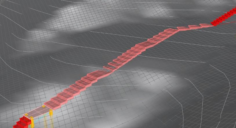
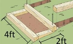
Stair Group Detailed Cost Estimate CEA/ETP R:CEA 12/06/22 5 of 11 ≔ Vba = ⋅ ⋅ wba lba hba 38.88 yd3 = Vba 39 yd3 8.In-groundstairs There are a total of 23 inground steps ≔n 23 Materials based on Vermont Manual 8.1Timber Drawing in the side shows the dimensions of the timber Pieces are 6" by 6", estimate is based on 6" by 6" wood, column framing ≔w 6 in ≔t =w 6 in linear feet of 4ft pieces ≔ l4 4 ft ≔ LF4 = ⋅n l4 92 ft linear feet of 2ft pieces ≔ l2 2 ft (Vermont) ≔ LF2 = ⋅ ⋅n l2 2 92 ft Totallinearfeet ≔LF = + LF4 LF2 184 ft Round Up ≔LF 190 ft Total2ftpieces ≔ n2 = ⋅n 2 46 Total4ftpieces ≔ n4 =n 23 8.2RebarGalvanized Length ≔L 18 in Diameter ≔D 1 2 in According to manual there is 6 rebar pieces in the first step and 4 in the rest. Thus the total is ≔ Totalrebar = 6+4⋅( ( -n 1) ) 94 Weight of total rebar ≔ wr 0.668 lbf ft (weight per foot of #4 rebar) ≔ wT = ⋅ ⋅ Totalrebar wr L 94.188 lbf = wT 0.047 tonf Round up = wT 0.05 tonf 8.3GalvanizedSpikes Non-Commercial Use Only
8.3GalvanizedSpikes
Length ≔L 12 in
According to the manual each step needs 2 spikes, except the first step ≔ Totalspikes = 2⋅( ( -n 1) ) 44
Spikes only cost about 66 cents each in a hardware store (Home Depot,2022), thus their cost was not included into the estimate since they would most likely be even cheaper when a contractor buys them
8.4Geotextile-Ingroundsteps
The geotextile needs to line the area inside each set of timbers, and long enough to extend a few inches up the sides.
Since the timber is 6" assumed that needed the geotextile to extend to 9" ≔SA = ⋅n ⎛ ⎝ + + ⋅ ⋅ ⎛ ⎝ - l4 0.75 ft⎞ ⎠ 0.75 ft 2 ⋅ ⋅ l2 0.75 ft 2 ⋅ ⎛ ⎝ - l4 0.75 ft⎞ ⎠ l2⎞ ⎠ 36.736 yd2
Round up =SA 37 yd2
8.5Crushedstone3/4"
On top of the geotextile goes crushed stone, but it is filled up to 1" below the top.
CYsto = ⋅ ⋅ ⋅n ( ( -w 1 in) ) l2 ⎛ ⎝ - l4 1 ft⎞ ⎠ 2.13 yd3 Round up ≔ CYsto 3 yd3
8.6SoilExcavation
This design requires soil excavation, will base amount on how much soil needs to be removed for each step. Assuming that need to excavate at least a foot deep for each step.
CYexc = ⋅ ⋅ ⋅n l4 ⎛ ⎝ + l2 w⎞ ⎠ 0.75 ft 6.389 yd3 Round up ≔ CYexc 7 yd3
9.Trail
There is a a small trail at the entrance to the stairs that connects to the bigger trail in LarimerPark ≔ Ltrail = 621 in 51.75 ft round up = Ltrail 52 ft
wtrail 3 ft
Atrail = ⋅ Ltrail wtrail 17.25 yd2 round up ≔ Atrail 18 yd2
Stair Group Detailed Cost Estimate CEA/ETP R:CEA 12/06/22 6 of 11 = wT
= wT
0.047 tonf
0.05 tonf
≔
≔
10.Railings Non-Commercial Use Only
≔
≔
10.Railings
There will be railings throughout the above-ground stairs and bridges
10.1
WoodRailing
The wood for the railings is 4" by 3" Need to find the linear feet needed of the hand rail.
4"x3"
Railings
Round up: = LR 440 ft The posts (4"x4") are 36" high and on average 70" apart thus the linear feet of the post is
h 36 in 4"x4" Posts
LP 230 ft
10.2steelwires There are 7 wires in each side and they go throughout the length of the stairs and bridge
LR 7 3052 ft Round up
11.GroundStabilization
LT 4000 ft
Total SY of geosynthetic soil stabilization, based on area that needs to be covered that is currently deemed to have very steep slopes Using geotextile as proxy for slopegrid, since no slope grid in in RS means
SY 10000 ft2 =SY 1111.111 yd2 Round up, since this is an estimate
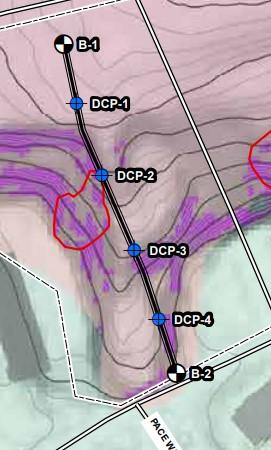
SY 1200 yd2 There will need to be 186 96in earth anchors, since there is no earth anchor in RS means, used GME Supply Co
anchor 186 number of earth anchors
Stair Group Detailed Cost Estimate CEA/ETP R:CEA 12/06/22 7 of 11
≔
=
⎛ ⎝ +
⋅ lst
⋅ lsL
⋅ l
lBT
⎞ ⎠
LR
2
+ + +
nft
nfl
L nL
lBL
436 ft
≔
≔
≔
⋅
≔
d 70 in
LP =
LR d h 224 ft Round Up
≔
⋅
LT =
≔
≔
≔
≔
≔
≔
⋅
II.LIFE
Non-Commercial Use Only
N
Panchor 273 dollars cost of one anchor
Tanchor =
Nanchor Panchor 50778 dollars
CYCLEASSESMENT
II.LIFECYCLEASSESMENT
Costestimateshowinginitialcapitalcostsandthenetpresentvalueoflifecyclecostsovera 50-yearlifespan
InitialInvestmentandReplacement
The cost estimate of the project can be seen in the RS means report. Total initial capital investment,P was approximately
≔P 113000 dollars
The lifecycle of the abovegroundstairs is estimated to be about 25 years (Traxion, 2021). This means that the stairs will need to be replaced at 25 years. We will assume that the stairs will be replaced with an exact copy, that cost a similar amount. We estimate this cost will be
≔ Fstairs 16000 dollars (this value excludes all costs associated with the inground stairs, bridge, demolition, and slope grid)
Since the deckofbridge is made of wood, it will need to be replaced occasionally. The lifespan of these deck is between 10 to 15 years (TimberTech, 2021). In this analysis we will assume it is 12 years. This means the deck will be replaced 4 times in the 50-year lifespan. Assume to cost of replacing is based on the original cost of the decking
≔ Fdeck 1320 dollars
Steelbridges have a lifespan of over 100 years (US Bridge, 2021). Even though the bridges in this project are not made completely of steel, will assume that the steel components will not be replaced in the next 50 years
We are assuming that the in-groundsteps will never be replaced completely, instead that a few boards will need to be replaced each year
MaintenanceandOperation:
Inspectionofbridgeandstairs-Yearly
The cost of having an inspection is between $0.25 to $2 per squarefoot (Homeadvisor, 2022). Will use the higher number of this range, due to accesability issues.
If assume that the total square feet of project is the slightly more than the square feet of decking, the project has approximately
≔SF 600 ft2 (calculated material takeoff is 510 square feet)
Inspection cost
≔ costinsp = ⋅ 2 ft2 SF 1200 dollars
Stair Group Detailed Cost Estimate CEA/ETP R:CEA 12/06/22 8 of 11 ≔ Tanchor = ⋅ Nanchor Panchor 50778
MaintenanceWorker Non-Commercial Use Only
MaintenanceWorker
Both the inground and above ground stairs will require routine maintenance both due to their location and material. Inground stairs will need to be cleaned out when clogging occurs. Stone, fabric, and wood may need to be replaced. Above ground steps will also have to be replaced occasionally and they will need to be cleaned often to avoid damage. It is hard to predict how many times this will happen and how much it will cost. It is simpler to find the cost of a maintenance worker and assume that their salary will be representative of the cost to maintain the park. Since the stairs are only part of the whole system, will assume that a worker is spending one fourth of their time on the stairs.
Maintenance worker cost ≔W = 39000 4 9750 dollars (salary.com 2022)
Total
Costof
Maintenance ≔M = +W costinsp 10950
For this net present value will use a real rate of return of 7% (Zerbe, 2018). This is the return after inflation, so will not include inflation in analysis. This number is seen as typical for goverment project
Equation for NPV
=NPV ⋅F ( (1+i) ) -n where F=future cost i=rate of return n=year
Figure that shows all costs over the 50 years
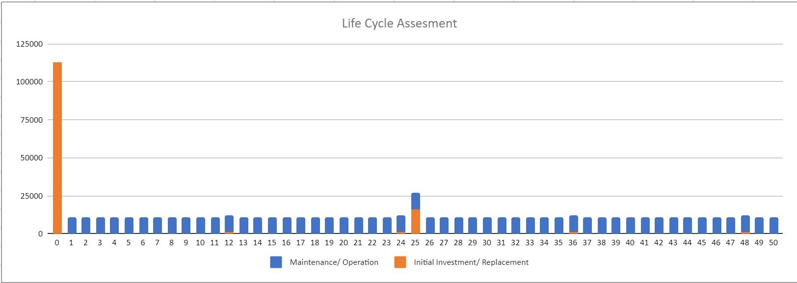
Stair Group Detailed Cost Estimate CEA/ETP R:CEA 12/06/22 9 of 11
Non-Commercial Use Only
Using excel the NPV of the project was
NPV is then ≔NPV 268000 dollars
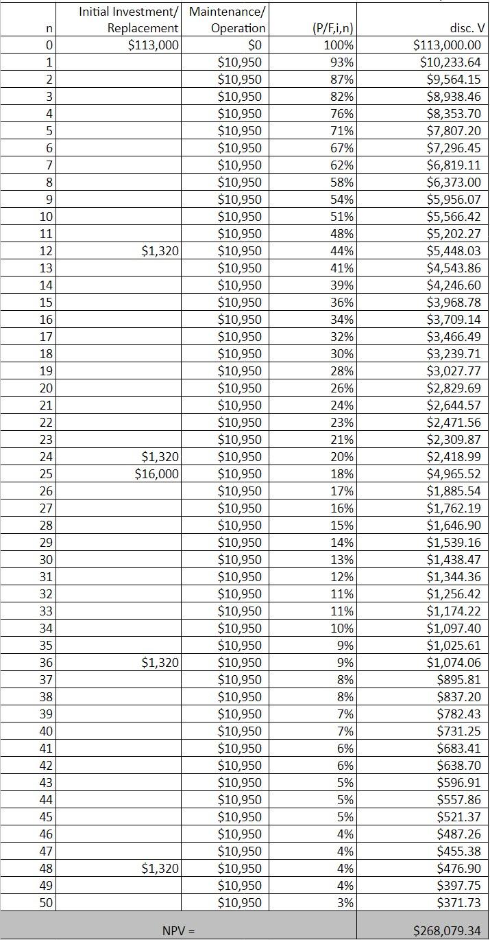
Stair Group Detailed Cost Estimate CEA/ETP R:CEA 12/06/22 10 of 11
Non-Commercial Use Only
Sources:
Galvanized Steel Earth Ground Screw Anchor (2022) "GME Supply is North America's Premier Outfitter of fall protection, safety equipment, and gear for at-height workers, industry, and construction." <https:// www.gmesupply.com/galvanized-steel-96-inch-earth-screw-anchor>
HomeAdvisor. (2022). "How Much Does a Structural Engineer Cost?" <https://www.homeadvisor.com/cost/ architects-and-engineers/hire-an-engineer/>
Negley Run Watershed Task Force. (2021). “Implementation Framework Little Negley Run at Larimer Park” <https://www.livingwaterspgh.org/wp-content/uploads/2022/01/LNR-Larimer-Park-ZoneBFINAL-2021-12-03-.pdf>
TimberTech. (2021). "How Long Does Decking Last? It Depends on Your Decking Material." <https:// www.timbertech.com/ideas/how-long-does-decking-last/#:~:text=THE%20AVERAGE%20LIFESPAN%20OF%20A %20WOOD%20DECK%3A%20Typically%2010%20to,with%20wood's%20rigorous%20maintenance% 20schedule.>
Traxion.(2021). "3 Indicators that it's time to repair your outdoor wooden stairs." <https://traxiontreads.com/3indicators-that-its-time-to-repair-your-outdoor-wooden-stairs/>
US Bridge.(2021). "The Lifespan of Structurally Deficient Bridges in America." <https://usbridge.com/thelifespan-of-structurally-deficient-bridges-in-america/>
Vermont Department of Environmental Conservation (Vermont DEC). (2022). “Infiltration Steps.” <https:// dec.vermont.gov/sites/dec/files/wsm/lakes/Lakewise/docs/LP_BMPInfiltrationSteps.pdf>
Zerbe, R. (2014). "What Should Be the Return on Public Investment?" <https://www.cato.org/regulation/ winter-2013-2014/what-should-be-return-public-investment>
Stair Group Detailed Cost Estimate CEA/ETP
12/06/22 11 of 11
R:CEA
Non-Commercial Use Only