148
SECTION IV DRIVE TRAINS
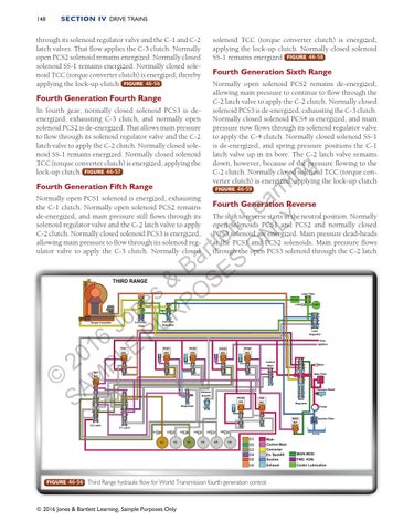
through its solenoid regulator valve and the C-1 and C-2 latch valves. That flow applies the C-3 clutch. Normally open PCS2 solenoid remains energized. Normally closed solenoid SS-1 remains energized. Normally closed solenoid TCC (torque converter clutch) is energized, thereby applying the lock-up clutch FIGURE 46-56 .
solenoid TCC (torque converter clutch) is energized, applying the lock-up clutch. Normally closed solenoid SS-1 remains energized FIGURE 46-58 .
Fourth Generation Sixth Range Normally open solenoid PCS2 remains de-energized, allowing main pressure to continue to flow through the C-2 latch valve to apply the C-2 clutch. Normally closed solenoid PCS3 is de-energized, exhausting the C-3 clutch. Normally closed solenoid PCS4 is energized, and main pressure now flows through its solenoid regulator valve to apply the C-4 clutch. Normally closed solenoid SS-1 is de-energized, and spring pressure positions the C-1 latch valve up in its bore. The C-2 latch valve remains down, however, because of the pressure flowing to the C-2 clutch. Normally closed solenoid TCC (torque converter clutch) is energized, applying the lock-up clutch FIGURE 46-59 .
Fourth Generation Fourth Range In fourth gear, normally closed solenoid PCS3 is deenergized, exhausting C-3 clutch, and normally open solenoid PCS2 is de-energized. That allows main pressure to flow through its solenoid regulator valve and the C-2 latch valve to apply the C-2 clutch. Normally closed solenoid SS-1 remains energized. Normally closed solenoid TCC (torque converter clutch) is energized, applying the lock-up clutch FIGURE 46-57 .
g n i
n r a e tt L LY N e l t O r a B ES & S s PO e n R o J PU 6 E 1 20 PL © AM S
Fourth Generation Fifth Range
Normally open PCS1 solenoid is energized, exhausting the C-1 clutch. Normally open solenoid PCS2 remains de-energized, and main pressure still flows through its solenoid regulator valve and the C-2 latch valve to apply C-2 clutch. Normally closed solenoid PCS3 is energized, allowing main pressure to flow through its solenoid regulator valve to apply the C-3 clutch. Normally closed
Fourth Generation Reverse The shift to reverse starts in the neutral position. Normally open solenoids PCS1 and PCS2 and normally closed PCS3 solenoid are energized. Main pressure dead-heads at the PCS1 and PCS2 solenoids. Main pressure flows through the open PCS3 solenoid through the C-2 latch
THIRD RANGE
Lube Filter
Cooler
Lube
Converter Regulator
Converter Flow
Torque Converter
Lube
PCS1 N/O
TCC N/C
PCS2 N/O
Lube Regulator Rear Splitline
PCS4 N/C
PCS3 N/C
Control Main
SS1 N/C
Exhaust Backfill
PCS5 N/C
SS2 N/C
Main Filter
Pressure Relief
Main Regulator
Diagnostic
C2 Latch
Main
Pump
MOD N/C
Suction Filter
C1 Latch C2
C1
C1
C4
C3
C2
C3
C6
C5
C4
C5
Sump C6
C1 C2
Main Control Main
C3 C4 C5
Converter Ex. Backfill
MAIN MOD.
Suction
FWD. KDN.
LU
Exhaust
Cooler Lubrication
FIGURE 46-56 Third Range hydraulic flow for World Transmission fourth generation control.
© 2016 Jones & Bartlett Learning, Sample Purposes Only