© Jones & Bartlett Learning, LLC. An Ascend Learning Company. NOT FOR SALE OR DISTRIBUTION CHAPTER 8 Diesel Engine Combustion Systems
bulence FIGURE 8-21 . The formation of emissions is reduced in these low-swirl quiescent bowls by increasing injection pressures and the number of spray holes at the injector tip. Most late-model engines use quiescent bowls combined with high-injection pressurization to mix air and fuel to achieve lower NOx emissions.
▶
Direct Injection
In a DI combustion chamber, fuel is injected directly into the combustion chamber, which is located between the top of the piston and the cylinder head. The combustion chamber is formed primarily in the piston and the cylinder head is flat. The fuel injector or spray nozzle, and the intake and exhaust valves, are located in the combustion chamber, directly above the piston. Higher engine thermal efficiencies are achieved using DI chambers because there is a small ratio between combustion chamber surface area and combustion volume. This results in 10–15% better fuel efficiency compared to IDI chambers because less heat is rejected or absorbed by the cooling system. Current thermal efficiencies are higher than 45% in newer on-highway engines and 50% or more in slower-turning industrial engines. Until the introduction of very high-pressure fuel injection systems and electronic control of injection timing, emissions from DI chambers were higher than IDI designs. Compression ratios in a DI chamber typically range between 15.5:1 and 17.5:1 for most on-highway diesel engines. The average compression ratio for on-highway vehicles is 16:1. At these compression ratios, pre-ignition air temperatures of 800– 1200°F (427–649°C) are produced, with an average pre-ignition temperature of 1000°F (538°C). When using air-to-air charge air cooling and a turbocharger, the typical compression pressure range is 300–1800 psi (21–124 bar). Peak cylinder combustion pressures may reach as high as 1800–2300 psi (124–159 bar) in small late-model diesel engines, and 3000 psi (207 bar) in large engines. This compares with maximum pressure of approximately 900 psi (62 bar) found in gasoline-fueled engines.
Quiescent Chamber
227
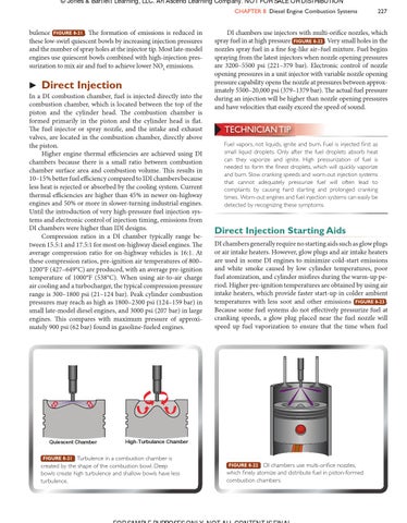
DI chambers use injectors with multi-orifice nozzles, which spray fuel in at high pressure FIGURE 8-22 . Very small holes in the nozzles spray fuel in a fine fog-like air–fuel mixture. Fuel begins spraying from the latest injectors when nozzle opening pressures are 3200–5500 psi (221–379 bar). Electronic control of nozzle opening pressures in a unit injector with variable nozzle opening pressure capability opens the nozzle at pressures between approximately 5500–20,000 psi (379–1379 bar). The actual fuel pressure during an injection will be higher than nozzle opening pressures and have velocities that easily exceed the speed of sound.
TECHNICIAN TIP Fuel vapors, not liquids, ignite and burn. Fuel is injected first as small liquid droplets. Only after the fuel droplets absorb heat can they vaporize and ignite. High pressurization of fuel is needed to form the finest droplets, which will quickly vaporize and burn. Slow cranking speeds and worn-out injection systems that cannot adequately pressurize fuel will often lead to complaints by causing hard starting and prolonged cranking times. Worn-out engines and fuel injection systems can easily be detected by recognizing these symptoms.
Direct Injection Starting Aids DI chambers generally require no starting aids such as glow plugs or air intake heaters. However, glow plugs and air intake heaters are used in some DI engines to minimize cold-start emissions and white smoke caused by low cylinder temperatures, poor fuel atomization, and cylinder misfires during the warm-up period. Higher pre-ignition temperatures are obtained by using air intake heaters, which provide faster start-up in colder ambient temperatures with less soot and other emissions FIGURE 8-23 . Because some fuel systems do not effectively pressurize fuel at cranking speeds, a glow plug placed near the fuel nozzle will speed up fuel vaporization to ensure that the time when fuel
High-Turbulance Chamber
FIGURE 8-21 Turbulence in a combustion chamber is created by the shape of the combustion bowl. Deep bowls create high turbulence and shallow bowls have less turbulence.
FIGURE 8-22 DI chambers use multi-orifice nozzles, which finely atomize and distribute fuel in piston-formed combustion chambers.
FOR SAMPLE PURPOSES ONLY. NOT ALL CONTENT IS FINAL 9781449624118_CH08_Pass02.indd 227
06/10/15 7:53 PM