NZ METAL ROOF AND WALL CLADDING CODE OF PRACTICE
FLASHINGS
5 V:2.2 PAGE 164
Waterproofing, release of curing agents or the moisture content of the slab can inhibit adherence of the sealant to the concrete. This area should be primed to ensure the sealant bond. 5.3.5.A and 5.3.5.C are not the preferred details . A better practice detail that provides more positive weathering is provided by covering the wall with vertical metal cladding up to the capping as shown in drawing 5.3.5.B. Where the roof sheeting stops short and does not extend to the wall, the unsupported apron flashing can have transverse fall back towards the internal angle of the apron flashing. It is not possible to ensure that all the water discharged from the apron flashing will be collected by the spouting at this junction unless special provisions are made including: • An angle diverter can be sealed and fastened to the apron. 5.3.5.C • Side apron flashing can be folded to 110˚. 5.3.5.D • Apron internal angle flashing can be folded to two angles @135˚. 5.3.5.E • A two piece apron 5.3.5.F For clarity the spouting has been omitted. Spouting should be fitted after the wall has been finished and should be 10mm clear of the wall cladding. Aprons should be stop ended and be turned down to weather and to bird-proof the end of the apron at this junction. N.B. Where a cavity parapet is used the apron should be in place before the cavity batten as it is not possible to retrofit the apron. The apron metal should have a durability of 50 years, unless the parapet cladding is easily replaced.
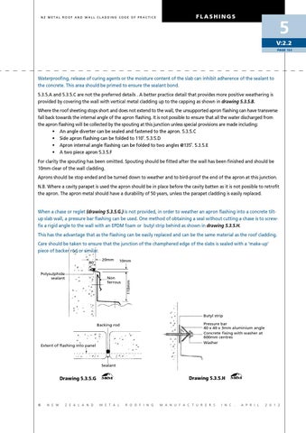
When a chase or reglet (drawing 5.3.5.G.) is not provided, in order to weather an apron flashing into a concrete tiltup slab wall, a pressure bar flashing can be used. One method of obtaining a seal without cutting a chase is to screwfix a rigid angle to the wall with an epdm foam or butyl strip behind as shown in drawing 5.3.5.H. This has the advantage that as the flashing can be easily replaced and can be the same material as the roof cladding. Care should be taken to ensure that the junction of the champhered edge of the slabs is sealed with a ‘make-up’ piece of backer rod or similar.
Polysulphide sealant
20mm
10mm
Non ferrous
110mm
80˚
Butyl strip Pressure bar 40 x 40 x 3mm aluminium angle Concrete fixing with washer at 600mm centres Washer
Backing rod
Extent of flashing into panel
Sealant
Drawing 5.3.5.H
Drawing 5.3.5.G
©
N E W
Z E A L A N D
M E T A L
R O O F I N G
M A N U F A C T U R E R S
I N C .
A P R I L
2 0 1 2