General Purpose Solid Carbide End Mills • Roughing/Finishing Recommended Roughing/Finishing - Speeds & Feeds Application Application DataData • Series D004 4004 • VariMill™ GP
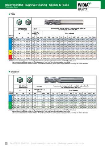
TiAlN
Side Milling (A) and Slotting (B) A Material Group
P
M K
ap
Recommended feed per tooth (fz = mm/th) for side milling (A). For slotting (B), reduce fz by 20%.
TiAlN Cutting Speed — vc m/min
B ae
ap
min
D1 — Diameter
max mm
1,0
2,0
3,0
4,0
5,0
6,0
8,0
10,0
12,0
14,0
16,0
18,0
20,0
0 Ap1 max 0,1 x D
0,5 x D
150 – 200
fz
0,007 0,014 0,021 0,028 0,036 0,044 0,060 0,072 0,083 0,092 0,101 0,108 0,114
1 Ap1 max 0,1 x D
0,5 x D
150 – 200
fz
0,007 0,014 0,021 0,028 0,036 0,044 0,060 0,072 0,083 0,092 0,101 0,108 0,114
2 Ap1 max 0,1 x D
0,5 x D
140 – 190
fz
0,007 0,014 0,021 0,028 0,036 0,044 0,060 0,072 0,083 0,092 0,101 0,108 0,114
3 Ap1 max 0,1 x D
0,5 x D
120 – 160
fz
0,006 0,011 0,017 0,023 0,030 0,036 0,050 0,061 0,070 0,079 0,087 0,095 0,101
4 Ap1 max 0,1 x D
0,5 x D
90
– 150
fz
0,005 0,010 0,016 0,021 0,027 0,033 0,045 0,054 0,062 0,070 0,077 0,083 0,088
1 Ap1 max 0,1 x D
0,5 x D
90
– 115
fz
0,006 0,011 0,017 0,023 0,030 0,036 0,050 0,061 0,070 0,079 0,087 0,095 0,101
2 Ap1 max 0,1 x D
0,5 x D
60
–
80
fz
0,005 0,009 0,014 0,019 0,024 0,029 0,040 0,048 0,056 0,063 0,070 0,076 0,081
1 Ap1 max 0,1 x D
0,5 x D
120 – 150
fz
0,007 0,014 0,021 0,028 0,036 0,044 0,060 0,072 0,083 0,092 0,101 0,108 0,114
2 Ap1 max 0,1 x D
0,5 x D
110 – 140
fz
0,006 0,011 0,017 0,023 0,030 0,036 0,050 0,061 0,070 0,079 0,087 0,095 0,101
NOTE: Lower value of cutting speed is used for high stock removal applications or for higher hardness (machinability) within group. Higher value of cutting speed is used for finishing applications or for lower hardness (machinability) within group. Above parameters are based on ideal conditions. For smaller taper machining centres, please adjust parameters accordingly on >12mm diameters.
Uncoated
Side Milling (A) and Slotting (B) A Material Group P
N
ap
Recommended feed per tooth (fz = mm/th) for side milling (A). For slotting (B), reduce fz by 20%.
uncoated Cutting Speed — vc m/min
B
D1 — Diameter
ae
ap
min
max
mm
0 Ap1 max
0,1 x D
0,5 x D
120
–
160
fz
0,007 0,014 0,021 0,028 0,044 0,060 0,072 0,083 0,101 0,114
1,0
2,0
3,0
4,0
6,0
8,0
10,0
12,0
16,0
20,0
1 Ap1 max
0,1 x D
0,5 x D
120
–
160
fz
0,007 0,014 0,021 0,028 0,044 0,060 0,072 0,083 0,101 0,114
2 Ap1 max
0,1 x D
0,5 x D
112
–
152
fz
0,007 0,014 0,021 0,028 0,044 0,060 0,072 0,083 0,101 0,114
1 Ap1 max
0,1 x D
0,5 x D
400
–
1600
fz
0,010 0,020 0,030 0,040 0,060 0,080 0,100 0,120 0,160 0,200
2 Ap1 max
0,1 x D
0,5 x D
400
–
1200
fz
0,008 0,016 0,024 0,032 0,048 0,064 0,080 0,096 0,128 0,160
4 Ap1 max
0,1 x D
0,5 x D
320
–
600
fz
0,007 0,014 0,021 0,028 0,042 0,056 0,070 0,084 0,112 0,140
NOTE: Lower value of cutting speed is used for high stock removal applications or for higher hardness (machinability) within group. Higher value of cutting speed is used for finishing applications or for lower hardness (machinability) within group. Above parameters are based on ideal conditions. For smaller taper machining centres, please adjust parameters accordingly on >12mm diameters.
widia.com
38 170
Tel: 01827 304500
Email: sales@itc-ltd.co.uk
Website: www.itc-ltd.co.uk