26 minute read
Oil & grease mg/lit Separating funnel method


Volume: 08 Issue: 08 | Aug 2021 www.irjet.net p-ISSN: 2395-0072
location Test Results
Advertisement
Point source Combined source
Shivgang a suzuki, Udyam nagar, Kolhapu r
pH 8.15 6.86 TDS 1150 1160 TSS 1700 760 Oil & grease 10.95 10.39 BOD 150 70 COD 360 140 Table- XI: Results station for 7th
These results are obtained by the water samples tested in the laboratory. That is the table no.7 indicates the values of each parameter for being tested. The point source is that source in which the uniform flow of water is observed such that on service station outflow such uniform flow of water is observed. Combined source is that source of water where the service station water and domestic wastewater or sanitary sewer water get mixed or combined to form the combined flow/source.
As these results get compares in graphical representation also it may be explained theoretically. The pH value obtained are in the limit of standardsso that there is no requirement of pH treatment but the TDS and TSS values exceeds the standard limit the proper screening or any other method is required to treat such a settable water. Oil and grease content arehigher in percentage as compared to standard so there is requirement of oily mixed water treatment. BOD is in the permissible limit that is amount of oxygen requires is in standard amount as COD is higher in amount for some service stations there is demand of treatment over that to reduce the percentage of COD.
6. RESULT
The result obtained from the testing the samples at laboratory it is clearly seen that the amount of pollution or the pollutant present in the service station wastewater plays major role in the water pollution. Here the no of collected samples of about 14.
Each service station contains two samples that is point source and combined source of wastewater outlet.
The details of each washing service station we discuss above but the graphical comparison with the standard is not done yet, so that the graphs from the study of comparison are plotted in this chapter and discussed it later on the treatment model for the service station will also be discussed in this chapter so that following are some graphs that shows the service station parameter variations for each of the washing station:
700 600 500 400 300 200 100 0
Point source Combined source
Graph–Station 1
1200 1000 800 600 400 200 0
Point source Combined source
Graph–Station 2
700 600 500 400 300 200 100 0
Point source Combined source
Graph–Station 3
3000 2500 2000 1500 1000 500 0
Point source Combined source
Graph–Station 4
pH TDS TSS Oil and grase BOD COD
pH TDS TSS Oil and grase BOD COD
pH TDS TSS Oil and grase BOD COD
pH TDS TSS Oil and grase BOD COD
Volume: 08 Issue: 08 | Aug 2021 www.irjet.net p-ISSN: 2395-0072
2000
1500
1000
500
0
Point source Combined source pH TDS TSS Oil and grase BOD COD
2000
1500
Graph–Station 5
1000
500
0
Point source Combined source
Graph–Station 6
1800 1600 1400 1200 1000 800 600 400 200 0
Point source Combined source pH TDS TSS Oil and grase BOD COD
pH TDS TSS Oil and grase BOD COD
Graph–Station 7
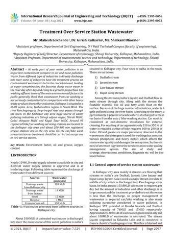
The project is aimed towards the recycle and reuses the wastewater at the location such that on the service station water discharges requires a proper management system and hence we design one prototype system for which the theory of design tank is needed on the basis of theoretical assumption prototype treatment design. Prototype model for treatment system is shown in fig.2:
Fig -2: Prototypetreatment system for treatment of service station wastewater The prototype model consists of following components: 1) Skimming tank 2) Sedimentation tank 3) Air diffuser 4) Mesh for screening 5) Valve 6) Pumping unit 7) Vent or Opening The design of treatment is based on theoretical assumption and practical knowledge. It can work practically as per my opinion this treatment mainly consists of two tanks one is skimming and another is sedimentation tank. Two tanks are sufficient to treat the service station wastewater. The components are described in below:
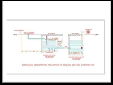
6.1 Skimming Tank
The tank which is used for the removal or disposal of oil and grease is the skimming tank. Tanks that drain oil and grate from the water build up before the sedimentation tank are skimming tanks. Municipal wastewater includes oil, fatty acids, waxes, soaps and so on. The greasy and oily substance may create a blurry smell on the settling tank surface or interfere with the process of activated sludge. In skimming tank air is expelled by an air diffuser at the bottom of the tank, along with chlorine gas. The rising air tends to coagulate or solidify the fat, causing it to climb up to the top of the tank when the protein protects by chlorine in emulsifying the fat. The fatty material is collected from the top of the tank and collected by specially designed mechanical or manual equipment.
Volume: 08 Issue: 08 | Aug 2021 www.irjet.net p-ISSN: 2395-0072
Fig. 3 – Schematic sketch for skimming tank
6.2 Sedimentation Tank
A sedimentation tank helps floating contaminants to flow gradually into the tank and thus have some cleaning of the surface or waste water. At the bottom of the tank is formed a layer of storage solids, called sludge, which is removed frequently. Suspension of solids in water those are more severe than water tends to settle gravitationally once the turbulence is delayed with the provision of stock.
The tank is called a settling tank in which the discharge is interrupted. It is called the statistical average time or detention time during which water is stored in the settling tank. Sedimentation elimination of suspended particles depends on their dimension, particle density and special gravity.
If their specific gravity resembles water and very small particles move through the filter will settle, suspended solids retained on a filter will stay in suspension. When the measurable mass collected on the base of the Imhoff cone after one hour has been settling down, dynamic solids are measured.
6.3 Air diffuser
Air diffuser: An aeration device, typical of disk, tube or plate type, used for the transmissionof air into the sewage or industrial waste water is an air diffuser or membrane diffuser. Amount of oxygen is expected to separate up pollutants by microorganisms / bacteria.
The typical efficiency of a potable water diffused deck treatment aeration system is 2% /ft submergence, or 6.6% /m. When translated to mass conversion into raw or polluted water, nearly half of those figures are typically nearest.
Fine bubble device manufacturers argued that "pores" are of great efficiency with regard to the form, number and scale of a large aerated device. The aeration system has two types that is coarse bubble and fine bubble tube and which are differ from each other. Although fine bubble diffusers and coarse bubble diffusers all operate through bubble aeration, certain notable features of their nature and operation need to be defined so that they can decide which is better.
Also, for aeration process, fine bubble salt tolerant generate lower bubble diameter. Such droplets usually have a circumference of 1–3 mm. typically this small blister aeration provides Standard Oxygen Transfer Efficiency (SOTE) 2 percent or more during aeration. Fine diffusers of bubbles themselves come in a number of sizes.
We have 7, 9 and 12 inch fine bubble diffusers for urban and industrial use at SSI Aeration for strength and reliability. In contrast to coarser bubble diffusers, a large bubble diameter makes the waste water efficiently moved, choked and mixed. Cross-bladder aeration generally provides 1% or less of SOTE during ventilation. SSI offers a number of coarsebubble diffusers at different points.
6.4 Air diffuser
The mesh used for screening categorized in to the fine screen and coarse screen at which the both are used according to the site location and the outflow and turbidity ofwastewater. Again, this fine and coarse screen divided into the fixed screen, band screen, disc screen, moving screen, drum screen each of them is having several functions.
In coarse fixed screen the safety of pumps, cylinders, tube lines, drives and associated equipment is to be provided. It is mounted before injection, main deployment or chamber with the waste water intake and is made of a network of rods or bars. Fine screen with maximum openings from 10 to 13 mm is located behind floor screens. Such screens are intended to avoid the accumulation of small waste such as rocks, barks, leaves, fish, etc. Fine fixed screen is good Fixed screens are suitable only for removing small quantities of content and sometimes only after the bar screen is mounted.
These screens have a 1-25 mm range of openings. Fine band screen consists of flexible wire mesh displays normally installed for the supply of a river. The flexible woven wire mesh is also fastened by a neighboring bar screen made of mild steel.
The orientation of such screens is vertical or horizontal. Jet is used to remove the garbage on the outside side of the panel from the interior of the displays. The mesh screen is also distributed on the basis of screening method as mechanically cleaned bar screen, manually cleaned bar screen, manually fixed bar screen depending upon the uses of these screens they are used on the site location also they may be divided on the basis of screening process as manually operated and automatically operated.
6.5 Valve
Valve is located in the middle of the skimming tank and sedimentation tank. The main function of valve is to maintain the detention time of both the tank.
Basically, the valves used for the underground constructions are observed as galvanized pipes but UPVC pipe linealso used for the underground construction and has several advantages like it is durable and having a great strength against the pressure of water.
Valve having the main function in the treatment as the
Volume: 08 Issue: 08 | Aug 2021 www.irjet.net p-ISSN: 2395-0072
detention time for each tank is maintained by the trap.
The valve operated manually by the operator as the water or wastewater enters into the first tank switch the valve into off mode that is skimming tank requires about 3-5 min of detention time to get the required result and then open the valve, water from the first tank enters the second tank when whole the water enters into second tank close the valve as done earlier so that about 2-3hrs required for the second tank to get the required output
Fig. 4 - Valve used intermediate of both tanks
Fig. 5 - UPVC pipes used for the tank construction this pipe with stand pressure up to 120 to 180Psi that depending upon the diameter of pipe.
6.6 Pumping Unit
The unit that is placed on the ground level and situated above the sedimentation tank is the pumping unit. The function of pumping unit is to lift the water which is remains after the process of sedimentation that water is used as recycle water for service station use. This water is not purified as the cleaned water but which is used for the service station to clean the car/bike. As the water is lifted by the pumping unit only that is mechanical operation necessary in the treatment.
6.7 Vent or Opening
The major aspect of treatment is the opening because the amount of oil and grease in water get separated in the skimming tank and removed these fatty acids by the manual work. Automatic operation can also be applied but due to economicsystem is held manual operation is necessary. As well as vents or openings are needed for the maintenance work of the tanks. The waterlevel and the process can also be seen by the vent or opening.
7. Discussion
Treatment over the service station as we discussed in result section, we require to proper understanding of each the component. Minimum of 1500 lit/day and max of 30,000 lit/day flows are observed on the service station on the basis of our study area. The amount of water discharges from the service station is higher in the case of workshops of public transport. As we define this treatment system on the basis of assumptions the treatment may work when the practical model is prepared. The treatment system can be broadly explained as below:
When the water from service station comes to the outlet such that which is drained directly into the sanitary sewer line or storm water line theonly process is screening process is held at present but due to our design treatment the screening is done by the mesh used. The mesh which we are using has several types according to function or the amount of TDS and TSS we use the required mesh that plays the role of screening.
After the screening of wastewater is done the amount of water directly entering into the skimming tank the skimming tank plays a major role in the separation of oil and grease from the water as well as heavy particles which are not soluble in water get lifted up and the separate container is provided to get the oil and grease amount into that container. Here firstly the skimming tank is having a baffle wall which plays as the major role to control the flow of water and water get diverted into the required direction. Purpose of baffle wall is to control the flow of water or the pressurize water get controlled by the baffle wall. The skimming tank also contains the air diffusers for the lifting of heavy greasy and oily partials to the upper surface of water level.
Air diffuser plays a vital role in the removing of oil and grease in water. Air diffuser has two types that are fine bubble tubes and coarse bubble tubes both are having several advantages and disadvantages over the water treatment. Here we use the air diffuser which has a layer of fine bubble as well as coarse bubble that is on over the another is placed for better diffusion of water.
Skimming tank requires about 2-5min for the process the flow is controlled by the valve which is in the mid of skimming and sedimentation tank. The pipe line should be adopted for the treatment used as PVC/UPVC type as this are better durable and high strength material. Valve should be used having such material and better durable also applicable for all the seasons.
When the water from the skimming tank is diverted after the process of skimming is done the amount of water
Volume: 08 Issue: 08 | Aug 2021 www.irjet.net p-ISSN: 2395-0072
received by the sedimentation tank takes the further process. Sedimentation tank also called as settled tank is the tank inwhich the smaller particles which are not separated in the skimming tank get deposited down into the sedimentation tank. These takes about 2-3 hours for the settlement of the particles.
Once the particle get settled at the bottom of the tank the amount of water remains in the sedimentation tank get pumped up with the help of water motor pump used for domestic purpose is sufficient for the lifting of water from the tank.
Hence wastewater from the service station can be recycled and reused by this process. There are advantages and disadvantages over this process they will discussed in the conclusion part also some point that is to be taken while handling the system also be explained. Small and large scale service station works with these system some stations where there is no treatment is carried out should use such treatment it helps in the maintaining the ecosystem. Oil and grease in skimming can be disposed manually or it can be helpful for the industries where the fatty acids are required like dye industry.
6. CALCULATIONS
Skimming tank:
It is arranged in a chamber so that floating material like oil, fat, graft, etc., rises and remains on the wastewater surface until it is removed.
Surface area of a tank is calculated by,
Where,
A = surface area q = rate of flow in /day Vr = Minimum rising velocity (m/min) = generally assumed as 0.24-0.24m/min
For each service station the surface area is calculated and on the basis of this the tank dimensions are decided:
1) Shri Mahalaxmi car/bike washing service station: Given,
The rate of flow of wastewater per day is 2000 liters/day such that 2 /day
q = 2 /day
Vr = 0.25m/min (assume) = 0.25x24x60
= 360m/day We get the surface area as, Now, provide the depth of tank as 1.5m The length to breadth ration assume as 1.5:1 So, L = 1.5B LxB = 1.5 ……(as LxB = A) B = 0.0048m L = 0.0096m The dimensions of the tank are 0.0096mX0.0048mX1.5m.
2) Shri Datta servicing center:
Given, The rate of flow of wastewater per day is 6000 liters/day such that 6 /day q = 6 /day
Vr = 0.25m/min (assume) = 0.25x24x60 = 360m/day
We get the surface area as,
Now, provide the depth of tank as 1.5m The length to breadth ration assume as 1.5:1 So, L = 1.5B LxB = 1.5 ……(as LxB = A) B = 0.0081m L = 0.012m The dimensions of the tank are 0.012mX0.0081mX1.5m.
3) Shetkari auto servicing center:
Given, The rate of flow of wastewater per day is 4000 liters/day such that 6 /day q = 4 /day
Vr = 0.25m/min (assume) = 0.25x24x60 = 360m/day
We get the surface area as,
Volume: 08 Issue: 08 | Aug 2021 www.irjet.net p-ISSN: 2395-0072
Now, provide the depth of tank as 1.5m The length to breadth ration assume as 1.5:1 So, L = 1.5B LxB = 1.5 ……(as LxB = A) B = 0.0068m L = 0.01m The dimensions of the tank are 0.01mX0.0068mX1.5m.
4) KMT workshop:
Given, The rate of flow of wastewater per day is 30,000liters/day such that 30 /day q = 30 /day
Vr = 0.25m/min (assume) = 0.25x24x60 = 360m/day
We get the surface area as,
Now, provide the depth of tank as 1.5m The length to breadth ration assume as 1.5:1 So, L = 1.5B LxB = 1.5 ……(as LxB = A) B = 0.019m L = 0.027m The dimensions of the tank are 0.027mX0.019mX1.5m.
5) ST workshop:
Given, The rate of flow of wastewater per day is 10,000 liters/day such that10 /day q = 10 /day
Vr = 0.25m/min (assume) = 0.25x24x60 = 360m/day
We get the surface area as,
Now, provide the depth of tank as 1.5m The length to breadth ration assume as 1.5:1 So, L = 1.5B LxB = 1.5 ……(as LxB = A)
B = 0.01m L = 0.016m The dimensions of the tank are 0.016mX0.01mX1.5m.
6) Riverside honda:
At the service station, treatment is already performed. Four tanks of 2500 L capacity and a filtration unit is placed at the center of the tanks, which is next to the washing plant and the water is then purified in accordance with the continuous process, and water is reused at service station.
7) Shivganga suzuki:
Given, The rate of flow of wastewater per day is 2000 liters/day such that 2 /day q = 2 /day
Vr = 0.25m/min (assume) = 0.25x24x60 = 360m/day
We get the surface area as,
Now, provide the depth of tank as 1.5m The length to breadth ration assume as 1.5:1 So, L = 1.5B LxB = 1.5 ……(as LxB = A) B = 0.0048m L = 0.0096m The dimensions of the tank are 0.0096mX0.0048mX1.5m.
6. CONCLUSIONS
The analysis and measurements of the service station are based on a study obtained as well as the literature survey conducted during the research. This cycle has the principal benefit of recycling water in the service station. Following care should be taken while handling the treatment system: -The mesh which is provided at the start of the treatment should be cleaned as the wastewater is continuously flowing there is production of clogs on the mesh so that the water for further process cannot be reached at desire amount. -Air compressor is required for the air diffuser process maintain the pressure from 3psi to 5psi depend upon the © 2021, IRJET | Impact Factor value: 7.529 | ISO 9001:2008 Certified Journal | Page 2107
Volume: 08 Issue: 08 | Aug 2021 www.irjet.net p-ISSN: 2395-0072
site conditions and the amount of outflow of wastewater. Chlorine dosage along with the air is effective for the disinfection in water. As per the site location the chlorine dosage with air is applied. Air diffusers are typically connected to the piping system which is supplied with the pressurized air by blower, The system commonly known as diffused aeration system or aeration grid. Aeration is used extensively for the biological oxidation of both domestic and industrial organic waste. It increases the percentage of oxygen in the water. This implies that aerobic process takes place in the air diffuser as aerobic process is a process that occurs and requires presence of oxygen pr air as opposed to an anaerobic process. -Skimming tank requires daily extraction of oil and grease which floats on the surface of water and get into separate container which can be removed easily either by manual or automated system is available. The disposal of skimming tank will be carried out by following method: -Deposit of skimming from the skimming tank is possible to produce soap, lubricants, paint, pitch and other items that cannot be consumed. Typically, burning or burning in the ground eliminates the slurry. If there is mineral oil and more organic and vegetables available in limited amounts. There are oils available thatcan be used for fuel gas production. -Sedimentation tank requires the maintenance work. The sludge which is settled down get cleaned daily for the proper working of treatment process the pipes which are used are to be either galvanized or to be PVC so that these pipes having the great strength and durability. -Valve which is used having a higher strength because the pressure of water will be handled by this valve. This are some advantageous and care taking point for the treatment process -Disadvantage of tank is that it requires the periodic maintenance such that scum and sludge cleaned daily also mesh used for screening will properly clean so that the amount of water flow maintained. Pumping station may also require some maintenance after some day. Air compressor having also periodic maintenance.
Other methods to treat the service station water are:
6.1 Grease trap:
A grate trap is a storage mechanism (a form of trap) designed to interact with most grades and solids, before accessing a drainage system for wastewater. Popular waste water includes oils accessing the sewage network and treatment plants for the creation of a liquid waste layer.
During anaerobic digestion this scum layer is very slowly digested and invaded by microorganisms. Fat, oils, and greases (FOGs) entering sewers are reduced by traps. These are manufactured from a wide range of items, such as steel, plastics, concrete and cast iron. The volume ranges between 35 and 45,000 liters and higher and can be placed over the ground also below the ground.
When the flow enters the grease trap, solid particles sink down and the lightest fat and oil float upwards. The water is then fed relatively fat-free in the normal septic system. The solids on the bottom, liquid oil and grease must be drained periodically, close to the filling of the septic tank.
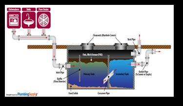
Fig. 6 – Grease trap
6.2 Techno- Commercial Offer for Effluent Treatment
Plant (ETP) for Car Wash Effluent by Flagship
India:
Following figure represent the treatment system held by the Flagship India for car washing:
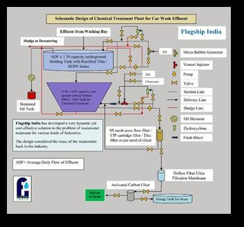
Fig No.7: Flagship India treatment plant over car wash service stations
Treatment consists of following steps or the operation features of the treatment are as follows:
Car washer effluent is collected from the collecting pit and flows into underground RCC / HDPE lined collecting tank cum equalization by gravity (or by pump if that may be required in a specific case).
Compacted air from the gracefully source gave by the customer is gone through diffusing layers to mix air to help oil buoyancy and microbial corruption with the assistance of unique microbial consortia in the tank
Volume: 08 Issue: 08 | Aug 2021 www.irjet.net p-ISSN: 2395-0072
presented by Flagship India. Effluent is re-circulated through transfer pump via Micro Bubble Generator to induce micro bubble in the effluent forcing the oil and grease to separate and float up.
Continuous oil removal is provided by belt type oil skimmer. Removed oil is taken to a sump for reselling or disposal. Hydro cyclone is used to partially remove sludge during recirculation flow. Transfer of raw effluent from underground collection tank into Batch Type chemical treatment chamber mounted on a skid (above ground) is done by pump with level control arrangement for automatic operation. Automatic online dosing of chemicals by venture injection system for chemical precipitation/neutralization is done before passing through spiral flow Cyclonic flash mixer. Hydro cyclone is used to remove sludge during recirculation flow. Add Bentonite @ 100-500 ppm (gm/M3) or up to the point when floating oil has disappeared after through mixing if oil skimmer is not installed.
It will also help in coagulation and quicker precipitation of sludge. Add Alum solution/Poly-Aluminum Chloride (PAC) slowly till coagulated particles show pin flocks. Test a small batch in a beaker to determine the exact dose. This addition of Alum / PAC will also help in Phosphorus removal. Add Chitosan @ 1 ppm (1gm/M3) if oil is present in the raw effluent and or Polyelectrolyte (such as the one supplied by SNF, Ashland-Hercules or equivalent) @ 10-50 ppm (gm/M3) till the pin flocks have turned into larger flocks and are clearly visible. If need be, small batch test should be conducted to determine the dose. At this point as the flocks will have clearly formed which means the coagulation is complete. So, it will be time for flocculation to begin. Check the pH. If it is in the acidic side, add prediluted lime/caustic solution till the pH reaches 7~7.5 while stirring well through mechanical stirrer or pump recirculation whatever is in the design.
Till this point if you are using a mechanical stirrer use it at 120-150 RPM for 10-15 min. Add pre-diluted anionic PAM (Poly-acryl-amide) in pre-diluted solution @ 2-10 ppm (2 gm to 10 gm of PAM powder/ M3) up to the point when all the flocks have come together and formed larger and quickly settling flock. In case of readymade PAM solution is used, the dose will be accordingly to the situation and strength of the preparation. During this flocculation phase use the stirrer at 10-20 RPM for 2-5 min. Stop all agitation and let the flocks settle down. Flocculated solids are now allowed to settle to the bottom of the chamber. Sludge from underflow goes to sludge drying bed for dewatering and subsequent municipal discharge.
Treated effluent from top goes to intermediate holding tank or directly from the chemical treatment tank for filtration as may be the design according to requirement. Filtration starts with 10-micron Stainless Steel Mesh filtration / Disc Filter / Sand Filter to be followed by Activated carbon Filter Modules taking out microorganisms, color, Suspended Solids. Hollow Fiber Ultra Filtration Membrane Filter is used as an option before Activated Carbon Filter to remove microorganisms, if that is needed.
Treated effluent after filtration unit can be used back in the car washing directly or via softener as per recommendation of the Car Washing Equipment Supplier, making this ecofriendly industry.
REFERENCES
[1] M.N. Asha, K.S. Chandan, “Recycling of Waste Water
Collected from Automobile Service Station”, Elsevier, 2015, pp.289-297.
[2] S.Nimal and Abdul Akber Shanaz Fathima, “ Recycling automobile service station wash center”, International journal of civil engineering and technology, April 2018, pp.795-802.
[3] A A Al-Gheethi, R M S R Mohamed, M A A Rahman1, M R
Johari1 and A H M Kassim, “Treatment of Wastewater
From Car Washes Using Natural Coagulation and
Filtration System”, IOP conf. series Materials Science and
Engineering, July 2016.
[4] W.J. Lau, A.F. Ismail, S. Firdaus, “Car wash industry in
Malaysia: Treatment of car wash effluent using ultrafiltration and nanofiltration memberanes”, Elsevier,
November 2012, pp.26-31.
[5] Debabrata Mazumder and Somnath Mukherjee,
“Treatment of automobile service station wastewater by coagulation and activated sludge process”, International
Journal of Environmental Science and Development,
February 2011, pp.64-69.
[6] J.C. Campos, R.M.H. Borges A.M., Oliveira Filho, Nobrega,
G.L. Sant’Anna, “Oilfield wastewater treatment by combined microfiltration and biological process”, Water research Elsevier, April2001, pp.95-104.
[7] C. Fall, C. M. Lopez-Vazquez, M. C. Jimenez-Moleon, K.M. Ba, C. Diaz-Delgado, D. Garcia-Pulido and M. LuceroChavez, “Carwashwastewaters: Characteristics, volumes and treatability by gravity oil separation”, Revista Mexicana de Ingenieria Quimica, July 2007, pp.175-184.
[8] R. N. Zaneti, R. Etchepare and J. Rubio, “Car wash wastewater treatment and water reuse –a case study”, Water science and technology, January 2013, pp.82-88.
[9] S. Adish Kumara, A. Kokila, J. Rajesh Banu,
“Biodegradation of automobile service station wastewater”, Desalination and water treatment, May 2013, pp.4649-4655.
Volume: 08 Issue: 08 | Aug 2021 www.irjet.net p-ISSN: 2395-0072
[10] Swapnil M. Kamble, “Water pollution and public health issues in Kolhapur city in Maharashtra”, International journal of scientific and research publication”,January 2014.
[11] A M Manilal, M G Harinarayanan Nampoothiri, P A
Soloman, “Removal of oil and grease from automobile garage wastewater using electro-coagulation”, IOP Conf.
Series: Materials Science and Engineering, June 2017.
[12] Dr. Krishna M. K, Dr. Manjunath H.N, Ayesha siddiqa,
“Treatment of service station wastewater using electrocoagulation process”, International Journal of Research
Granthalaya, July 2017, pp.348-353.
[13] Pranita P. Wadkar and Sachin J. Mane, “Low cost treatment to automobile wastewater service center”,
Global Research and Development Journal of
Engineering, March 2016, pp.238-240.
[14] Carlos Banchon, Alexandra Castillo, Paola Posligua,
“Chemical interation to clean up highly polluted automobile service station wastewater by bioadsorbantcoagulation-flocculation”, Journal of Ecological
Engineering, January 2017, pp.1-10.
[15] Mrs. Bharati S. Shete and Dr. N. P. Shinkar, “Use of membrane to treat car wash wastewater”, International
Journal for Research in Science & Advanced
Technologies, 2014, pp.13-19.
[16] Rohan A. Walzade, Aditya G. Koul and Prof. Gaurav B.
Daware, “degradation of pollutants from automobile service station by using heterogeneous photocatalysis”,
International Journal of Trend in Research and
Development, 2016, pp.151-154.
[17] Ishwar P. Patil, Prof. Hemant D. Wagh and Prof. (Dr.)
Arun Kumar Dwivedi, “Water recycle and reuse-a case study of NMIMS University campus”, International
Journal of Engineering Invention, September 2013, pp.10-17.
BIOGRAPHIES
Mahesh Ananda Lokhande
received his M.tech in Environmental science and technology from Departement of technology, Shivaji University. Currently working as Assistant Professor in Department of Civil engineering, D Y Patil technical campus, Talsande, Kolhapur.
Girish Shrinivas Kulkarni
received his M.E in Environmental Engineering from Shivaji university & Doctor of Philosophyin Civil (Environmental) Engineeringunder Faculty of Engineering & Technology,Walchand College of Engineering, Sangli affiliated to Shivaji University, Kolhapur onTechno-economical feasibility of using Solar Energy for Environmentally sustainableBuildings. He has got experience in many fieldssuch as, 1.5 Years in Public Works Department of Maharashtra State Government as Asst. Engineer, 11 Years Deputy Registrar (Civil) Shivaji University, Kolhapur, presently working as‘Director’ Department of Technology,Shivaji University, Kolhapur from May, 2010 onwards. He is TrusteeDnyandeep Education & Research Foundation, Sangli., Member Environmental Protection & Research Foundation, Sangli, Member Institution of Engineers (India). 13 M.tech scholars have been awarded under his supervision and currently he is supervising 5 PhD scholars.
Shrikant Malhararao Bhosale
received hisM.E in Structures from Shivaji University. Currently working as Assistant Professor in Department of technology Shivaji university Kolhapur. He worked as a Deputy registrar (Civil) in Shivaji university. 03 M.tech scholars have been awarded under his supervision.