4 minute read
Responsereductionfactor

from IRJET - Design and Weight Optimization of Integrated Super Bracket According to Stress Analysis

International Research Journal of Engineering and Technology (IRJET) e-ISSN: 2395-0056 Volume: 07 Issue: 08 | Aug 2020 www.irjet.net p-ISSN: 2395-0072
Story6 Story7 Story8 Story9 Terrace
Advertisement
Story
Base Story1 Story2 Story3 Story4 Story5 Story6 Story7 Story8 Story9 Terrace AdditionalStory1 AdditionalStory2 AdditionalStory3 29.414 35.351 40.163 43.507 45.558 27.451 33.284 38.414 42.59 46.042 48.831 50.832 10.773 16.539 21.765 26.331 30.012 33.012 35.39 36.972 3.468 7.502 11.313 16.604 20.669 23.736 25.649 26.096 3.688 4.731 5.785 6.815 7.803 2.848 3.836 4.863 5.9 6.934 8.005 9.279
Table-III: DisplacementatfloorlevelsforallmodelinXdirection Table-IV: BaseshearandroofdisplacementforallmodelinXdirection Table-V: BaseshearandroofdisplacementforallmodelinXdirection 1.241 1.923 2.671 3.458 4.254 5.048 5.868 6.831 0 0.027 0.101 0.195 0.347 0.534 0.754 1.052 1.369 1.693 2.015 2.168 2.245 2.333 0.375 0.723 1.137 1.606 2.086 2.567 3.08
AdditionalStory1 AdditionalStory2 AdditionalStory3
15 BC
0 0 8.99 16.695 24.358 31.469 38.017 43.714 48.213 51.167 51.292
25 BC
0 0.278 2.331 6.701 12.32 18.453 26.568 33.997 40.65 46.271 50.725 53.93 55.83
35 BC
0 0.36 2.601 5.171 8.196 11.973 16.624 21.894 26.601 30.566 33.981 37.889 40.666 42.19
45 BC
0 0.147 1.128 2.325 2.972 3.273 3.602 4.499 4.375 4.402 4.407 3.568 2.726 1.884
15 SW
0 0.002 0.359 0.568 0.946 1.375 1.828 2.288 2.746 3.185 3.318
25 SW
0 0.044 0.152 0.336 0.574 0.853 1.205 1.579 1.962 2.341 2.749 3.119 3.599
35 SW
3.883
45 SW
0 0.01 0.096 0.195 0.235 0.354 0.491 0.648 0.812 1.034 1.255 1.305 1.266
MODEL NAME 15BC 25BC 35BC 45BC 15SW 25SW 35SW 45SW BASESHEAR KN 2292.1751 2032.7571 1892.5504 2192.407 2830.0571 2576.4929 2299.9068 1961.4114 DISPLACEMENT mm 45.558 50.832 36.972 26.096 7.803 9.279 6.831 3.883
1.204
MODEL NAME 15BC 25BC 35BC 45BC 15SW 25SW BASESHEAR KN 2485.9988 2251.5719 2115.8441 793.8813 3069.3634 2853.8377 DISPLACEMENT mm 51.292 55.83 42.19 1.884 3.318 3.599
International Research Journal of Engineering and Technology (IRJET) e-ISSN: 2395-0056 Volume: 07 Issue: 08 | Aug 2020 www.irjet.net p-ISSN: 2395-0072
35SW 45SW 2571.2628 2192.8298 2.333 1.204
Modes 15 BC Period (sec) 25 BC
1.208 1.14 0.992 0.389 0.377 0.328 0.223 0.222 0.194 0.16 0.156 0.137 1.303 1.223 1.097 0.44 0.407 0.375 0.273 0.255 0.235 0.195 0.187 0.168 TableVI:Modeshapesvariationforallmodels inVdirection
35 BC 45 BC 15 SW 25 SW
1.143 1.118 0.978 0.403 0.399 0.348 0.274 0.266 0.223 0.212 0.2 0.179 0.866 0.835 0.738 0.348 0.323 0.278 0.253 0.246 0.195 0.194 0.179 0.164 0.421 0.27 0.208 0.102 0.078 0.07 0.069 0.057 0.053 0.049 0.049 0.049 0.468 0.277 0.227 0.149 0.134 0.102 0.079 0.06 0.053 0.051 0.042 0.037
35 SW
0.416 0.267 0.186 0.139 0.128 0.091 0.075 0.074 0.073 0.072 0.068 0.06
45 SW
0.313 0.227 0.137 0.132 0.128 0.126 0.123 0.116 0.095 0.075 0.073
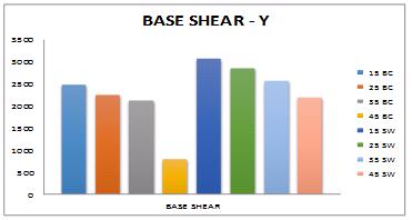
Graph-I: StoreyDisplacementinXDirection Graph-III: Baseshearandroofdisplacementforallmodel inXdirection
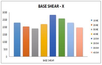
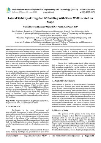
Graph-II: StoreyDisplacementinYDirection Graph-IV: Baseshearandroofdisplacementforallmodel 0.052
International Research Journal of Engineering and Technology (IRJET) e-ISSN: 2395-0056 Volume: 07 Issue: 08 | Aug 2020 www.irjet.net p-ISSN: 2395-0072
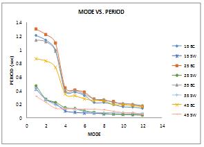
Graph-V:Modevs.periodvariationforallmodels
5. CONCLUSIONS
A.StoreyDisplacement
1. Performance of all beam column models having higher displacementvaluesinXandYdirection.
2. Model 25BC and 25SW shows maximum storey displacementwhichclearseffectofangletorsioninvertical elementinXandYdirection.
3.Model15BCshowslessdisplacementinXandYdirection as compared to 25BC model it may due to less angle distributed lateral load uniformly and very less column subjectedshortcolumneffect.
4. All Shear wall models (SW) performed well in X and Y directionandshowsverylessstoreydisplacementeveninY direction where slope is along Y direction. It is due to increasedstiffnessdueadditionofshearwallandreduced heightofshearwall.
B.BaseShearanddisplacement
1.Baseshearofmodel35BC,45BCand35SW,45SWobserved as lowest and model 15SW and15BC observed as highest valuesinX.Fromthisitisclearthatasslopeangleofground increases with respect to horizontal the height of vertical element columns/shear wall reduces and reduced height increases stiffness which attracts the more lateral force. increaseofstiffnessi.ereplacementofcolumnbyshearwall.
2.Reductionofdisplacementobservedmaximumincaseof model 45SW when compared to all other models which counts to be only 9% and 3% respectively in X and Y direction. In Y direction model 45BC shows maximum reductionindisplacementascomparedtoXdirectionitis duetogroundslopeisinydirection.
C.ModeVsFundamentalTimeperiod
1.Timeperiodisreducingwithrisinggroundslopeangles.2. Model15BC,25BCand35BCshowshighertimeperiod(i.e> 1sec) in their first mode as compared to all other models.
© 2020, IRJET |
This indicates flexibility or deformability of structure whereas less time period denotes stiffer structure. 3. first three modes of all BC models having reduction in time periodfrom3%to14%whichshowsstiffertoflexiblemodel andallSWmodelsshowsreductionintimeperiodfrom22% to55%.AsperIS1893:2016themodaltimeperiodshouldbe apart at least by 10%. This clears shear wall models performedwell.
REFERENCES
[1]B.G. Birajdar and S. S. Nalawade,“Seismic analysis of buildings resting on sloping ground”.In Thirteenth World Conference on Earthquake Engineering (13WCEE), 2004, Vancouver,Canada.
[2]S.M.Nagargoje and K.S.Sable,”Seismic performance of multistoreyed building onsloping ground’’, Elixir InternationalJournal,7December2012.
[3]Y.Singh,“SeismicBehaviorofBuildingsLocatedonSlopes” -AnAnalyticalStudyandSomeObservationsFromSikkim EarthquakeofSeptember18,2011.15thWorldConference onEarthquakeEngineeringJournal2012.
[4]ArangoandUribe,”Commonpracticeingrowing cities located in mountainous regions to undertake the constructionofbuildings”.iternationalSymposiumonNew TechnologiesforUrbanSafetyofMegaCitiesinAsia(USMCA 2013)ReportNo:IIIT/TR/2013/-1.
[5]D.H.LangandE.Erduran,“Buildingsinhillyareashaveto beconfigureddifferentlyduetoscarcityofflatground”.An analytical study and some observations from Sikkim earthquake of September 18, 2011. 15 WCEE, Lisbon, Portugal.
[6]JosephandPhadtare,“Effectofearthquakeonstepbacksetback structure with bracing on different slope of ground”.Thesis(1996),Earthquakeengineering,Universityof Roorkee,Roorkee.
[7]RavikumarC M,Babu NarayanKS,“EffectofIrregular Configurations on Seismic Vulnerabilityof RC.Buildings”. ArchitectureResearch2012,2(3):20-26DOI: 10.5923/j.arch.20120203.01.
[8]Rayyan-Ul-HasanSiddiquiand,H.S.Vidyadhara,“Seismic AnalysisofEarthquakeResistantMultiBayMultiStoreyed 3D – RC Frame” International Journal of Engineering Research & Technology (IJERT) ISSN: 2278- 0181 Vol. 2 Issue10,October–2013.
[9]Dr.S.A.Halkude,“SeismicAnalysisofBuildingsResting on Sloping Ground With Varying Number of Bays and Hill Slopes”InternationalJournalofEngineeringResearchand Technology ISSN:2278- 0181,Vol.2 Issue 12, December2013.