10 minute read
Chemical Composition analysis for sample defective casted metal

from IRJET- Defect Analysis for Sand Casting Process (Case Study in Foundry of Kombolcha Textile Share Co

International Research Journal of Engineering and Technology (IRJET) Volume: 07 Issue: 01 | Jan 2020 www.irjet.net e-ISSN: 2395-0056 p-ISSN: 2395-0072
Grain fineness number (GFN) =
Advertisement
Grain fineness number (GFN) 16.74 determined by experiment is very small number, it indicates this sand is very coarse which has very small fineness number less than the average fineness number which varies for cast iron from 45-65 and light alloys(e.g.Aluminium) 70-100 [13]. Table 2. Measured and calculated sieve analysis data
Sieve No. Diameter of Sieve hole
6 mesh 3.35mm 12 mesh 4.70mm 20 mesh 850mm 30 mesh 600 µm 40 mesh 425 µm 50 mesh 300 µm 70 mesh 212 µm 100 mesh 150 µm 140 mesh 106 µm 200 mesh 75 µm 270mesh 5.3 µm Pan
Total
Weight of sieve
482.52 407.42 370.84 349.17 339.26 331.06 307.73 306.12 306.14 300.34 293.76 276.56 Weight of Retained sand sieve 488.89 416.57 389.30 355.29 342.01 332.54 308.84 306.91 306.71 300.71 293.84 276.563 Weight retained sand
(g) 6.37 9.15 18.46 6.12 2.75 1.48 1.11 0.79 0.57 0.37 0.08 0.003
(%) 13.46% 19.34% 39.02% 12.95% 5.82% 3.14% 2.34% 1.68% 1.21% 0.79% 0.17% 0.01%
99.93
Multiplying Factor
2 6 12 20 30 40 50 70 100 140 200 270 Product
26.92 116.04 468.24 259 174.6 125.6 117 117.6 121 110.6 34 2.7 1673.3
Chemical Composition analysis for sample defective product
The test was conducted in foundry laboratory of Akake basic metals industry, Ethiopia.
Laboratory equipment used: Spectrometer
Sample of defective cast iron part was taken and the following composition analysis was found.
C 3.67 Si 2.00 Mn 0.482 Table.3 Composition of cast iron sample
P 0.183 S 0.164 Cr 0.074 Mo <0.003 Ni 0.057 Al 0.025 Co <0.009 Cu 0.092 Nb <0.005
Ti 0.027 V 0.016 W <0.040 Pb <0.010 Sn 0.006 Mg <0.002 As 0.016 Zr <0.003 B <0.001 Fe 93.1
Composition of metal determines the desired strength and metallurgical structure of the parts to casted. In case of ferrous casting, it is necessary to know the percentage of Carbon, Silicon, Sulphur, Manganese, and Phosphorous
International Research Journal of Engineering and Technology (IRJET) Volume: 07 Issue: 01 | Jan 2020 www.irjet.net e-ISSN: 2395-0056 p-ISSN: 2395-0072
contents. To get the actual structure of cast iron, carbon in the range of 3.5-4%,silicon in the range of 13%,manganese in the range of 0.4-1%,phosphrous no to exceed 1% and Sulphur kept below 0.05%.[13]
The above spectroscopic analysis indicates that all the required elements are in correct composition range to produce parts from cast iron with actual structure and without shrinkage defect which result from unsuitable metal composition.
All major causes and sub-causes indicated on the fish-bone diagram were experimentally tested and practically absorbed. Causes which were responsible for those defects were identified and possible remedies were suggested as shown in the table below.
Table 1. Shows defect type, the major cause, tested sub-causes, observed sub-causes and possible remedies No.
1. Defect type
Blowholes and pinholes Major causes Mould making
Pattern making
Risers and gating system design Melting And pouring practice Tested subcauses Clay content test (52.7%) (very low permeability which cause gas or air entrapment) Practically observed subcauses
Insufficient venting
Sharp corner of patterns (gas may accumulate at corner of mould cavity)
Improper gating system design (which cause turbulence and aspiration of air) Too low or high pouring temperature Improper pouring Melt no sufficiently degasified Possible remedies
Use molding sand which have the following required properties (dry sand moulding) Fineness number between 45 –65 for cast iron and alloys (e.g.Aluminium) 70100. Clay content ≤ 2% Permeability 100-150 Use venting at sharp corner Avoid sharp corner during pattern making Correct pattern design procedure Proper design of gating system
Use temperature measuring instrument suchas pyrometer Adjust pouring time
Shrinkage cavity Pattern making
Risers and gating system design
Melting and pouring practice Abrupt change in sectional thickness Improper allowance Risers Inadequate size and wronglocation Improper gating system design
High pouring temperature Follow correct pattern design procedure
Design the correct size of the riser and determine feed ranged Calculate and determine gating system size and direction Control pouring temperature using temperature measuring instrument like pyrometer
International Research Journal of Engineering and Technology (IRJET) Volume: 07 Issue: 01 | Jan 2020 www.irjet.net e-ISSN: 2395-0056 p-ISSN: 2395-0072
Sand burn on Mould making
Melting and pouring practice High moisture content of sand (this is due to high clay content)
High pouring temperature Use sand with low cay content. Use of coal dust Control pouring temperature using temperature measuring instrument like pyrometer
Notice. Those major cause and sub-cause which were on correct design, composition and working procedure are not listed in the above table.
But for sand burn-on sub-causes such as amount of low melting impurities and lustrous carbon content were not tested due to absence of gas determinator. Here conclusion was done for moisture content with respect to clay content and unknown pouring temperature.
4. Casting experiment for remedial actions
Casting experiment was done for one of the common products, brake casing of the weaving machine, in foundry of kombolcha textile Share Company. The following remedial actions were done for this selected product.
Figure 9. Isometric view of brake casing
4.1. Change of moulding sand
Reclaimed sand (used sand) with the following properties was brought from foundry of federal medium and small enterprise agency, Ethiopia.
Grain fineness number = 40.19
Clay content = 1.5%
Figure.10 Reclaimed moulding sand brought from foundry of Federalsmall and micro enterprise development agency,Ethiopia.
International Research Journal of Engineering and Technology (IRJET) Volume: 07 Issue: 01 | Jan 2020 www.irjet.net e-ISSN: 2395-0056 p-ISSN: 2395-0072
4.2. Pattern design
The pattern was designed and manufactured for selected product by following the correct pattern design procedure. It results the split pattern as shown below.
Type:
split pattern Material of pattern: Aluminum
Allowance: Contraction allowance of 10.5mm/M and Machining allowance of 3mm were given for cast iron [13] .

a) Left part of split pattern b) Right part of the split pattern
4.3. Design of gating system Figure 11.
Isometric view of split pattern
To avoid turbulence and to have smooth metal flow, the gating system for the selected product was designed. Here design analysis for determination of pouring cup, sprue size, choke area, runner size, pouring time required, average filling time of the casting and effective metal head of the casting was done. At the end, appropriate gating system that is pressurized gating system with ratio 4:1 was selected and based on sprue design, taper sprue cutter was manufactured. The following figure is resulted dimensions of sprue, sprue well, and two gates for gating ratio 4:1.
35.84
Dimensions are in mm
150
8
16 31.16
62.32 Figure 12. Dimension of Sprue, Sprue well and two gates in mm for gating ratio 4:1
International Research Journal of Engineering and Technology (IRJET) Volume: 07 Issue: 01 | Jan 2020 www.irjet.net e-ISSN: 2395-0056 p-ISSN: 2395-0072
Procedures for Experiment
Pattern was manufactured as shown figure (a) below based on designed dimension. Sprue cutters (figure.b below) was manufactured based on the dimension of sprue as shown in figure 12.Starting from pattern making up to finishing, the following are casting steps which was done.

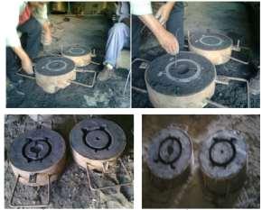
a)
Split Patterns b) Sprue cutter for gating ratio 4:1 c) During mould making

e) Assembled mould ready for pouring

f) Melting process g) Pouring process
i ) After sand removal by hand h) After shake out
grinding
International Research Journal of Engineering and Technology (IRJET) Volume: 07 Issue: 01 | Jan 2020 www.irjet.net e-ISSN: 2395-0056 p-ISSN: 2395-0072
5.1. Results and discussion
j) After machining
Three experiments were conducted. Testing of moulding sand, clay content test (52.7%) and grain fineness number (GFN) (16.74) indicated that the sand in this foundry is not moulding sand. It cannot use for mould making process. It was main reason for the defects to occur. Therefore, it must be removed and substitute by other moulding sand.
During metal composition analysis of defective parts, alloys content was in the required range. Therefore, it was not responsible for the defects to occur.
Incorrect pattern design, wrong gating system design and uncontrolled melting process were absorbed which were the causes for defects. In order to minimize those problems, correct working procedure must be followed.
For remedial actions, experimental test was done using other moulding sand, correct pattern design and gating system design for brake casing of weaving machine. But the problem absorbed during the experiment were difficulty in mould making andrough casting surface due to coarseness of this reclaimed sand and sand burn on also absorbed.
6. Conclusions
From defect analysis, the defects in this foundry were gas porosity (blowholes and pinholes) and shrinkage porosity. The mainreason for these defects was high clay content (52.7%) of the previous sand, unknown melting temperature, incorrect gating system and pattern design.
Experiment for remedial action resulted with conforming casting product for designed pressurized gating system (gating ratio 4:1). Thisis because the flow is streamlined and defect due to turbulence is avoided, the sand used for mould making has high permeability therefore no air or gas entrapment which causes blowholes or pinholes. The pattern and gating system design werecontrolled to avoid blowholes, pinholes and shrinkage.
For production of quality casting parts, this foundry must provide other moulding sand and control of other process parameters during pattern making, gating system design and pouring practice is important.
Acknowledgements
I amappreciatively thankful to Wollo university research and Communityservice, for sponsoring the research. I am equally grateful to Kmobolcha textile Share Company for their full collaboration for this research work, Akaki basic metals industry their contribution to test composition of metal by spectrometer and Federal Micro and Small enterprise development agency for permission of their sand testing equipment to test moulding sand.
International Research Journal of Engineering and Technology (IRJET) Volume: 07 Issue: 01 | Jan 2020 www.irjet.net e-ISSN: 2395-0056 p-ISSN: 2395-0072
REFERENCES
[1]. Aniruddha Joshi and L.M.Jugulkar,Investigation and analysis of metal casting defects and defect reduction by using quality control tools,international journal of mechanical and production engineering,volume 2,issue-4,April2014.
[2] A.P.More, Dr.R Baxi, Dr.S.B.Jaju, Review of casting defect analysis to initiate the improvement process, int.J Engg, vol.4, pg (292-295), (2011)
[3]. B.chokkaligam and S.S.Mahammed Naziruden,analysis of casting defect through defect diagnostic study Approach,Journal of engineering annals of faculty of engineering Hunedoara,2009
[4].Dr.B.Ravi, Casting simulation and Optimization: Benefits, Bottlenecks, and best practices, Indian foundry journal, (2008)
[5].Dr.B.Ravi, Durgesh Joshi, feadibility analysis and optimization Driven by casting simulation, Indian journal, (2007)
[6]. Dr.D.N.Shivappa,Mr.Rohit and Mr.Abhijit Bhattacharya,analysis of casting defects and identification of remedial measures-a diagnostic study,international journal of engineering Inventions,2012.
[7].Dr.Hathibelagel Roshan, process optimization as a tool in the analysis of steel casting defects, Maynard steel casting company
[8].G.S.Cellini,L.Tomesani,Metal head-dependant HTC in sand casting simulation of aluminum alloys, journal of achievements in materials and manufacturing engineering,vol.29,pg(47-52),(2008)
[9]. I.Vaskava,D.Fecko and L.Eperjesi,Comparison of simulation programs Magmasoft and Nova flow & Solid in terms of results accuracy, Archives of foundry Engineering,2011.
[10] L.A.Dobrzanski, M.Krupinski, J.H.Sokoski, P.Zarychta, A.Wlodarczyk-Fligier, Methodology of analysis of casting defects, journal of achievements in materials and manufacturing engineering,vol.18,pg(267-270),(2006)
[11].L.A.Dobrzanski,M.Krupinski,P.Zarchta,R.Maniara,analysis of influence of chemical composition of Al-Si-Cu casting alloy on formation of casting defects, journal of achievements in materials and manufacturing engineering,vol 21,pg(53-56),(2007)
[12] L.A.Dobrzanski, M.Krupinski, R.Maniara, J.H.Sosolowski, computer aided method for quality control of automotive Al-Si-Cu cast components, journal of achievements in materials and manufacturing engineering,vol.24,pg(151-154),(2007)
[13]. P L Jain, Principle of foundry technology, Tata McGraw-Hill,New Delhi,fourth edition,2007.
[14]. P.Prabhakara,Rao,G.Chakravethi,A.C.S.Kumar and B.Balakrishna,Application of casting simulation for sand casting of a crusher plate,International journal of thermal technologies,vol.1.no.1(Dec.2011)
[15]. Prof.Tushar M.paltel and Mr.Ankit Doza, Analysis and validation of gravity die casting process using procast, IJAIEM, Vol.2.Issue,April 2013.
[16]. Rajesh Rajkahe and J.G.Khan,Defects,causes and their remedies in casting process,International journal of research in advent technology,vol.2,No.3,March 2014.
[17]. R.S.Ransing,M.N.Srinivasan,R.W.Lewis,ICADA:Intelligent computer aided defect analysis for casting ,journal of intelligent manufacturing,vol.6,pg(29-40),(1995).
[18]. Sunil Chaudhari and Hemant Thakker,Review on analysis of foundry defects for quality improvement of sand casting,Journal of engineering research and applications,march,2014.