6 minute read
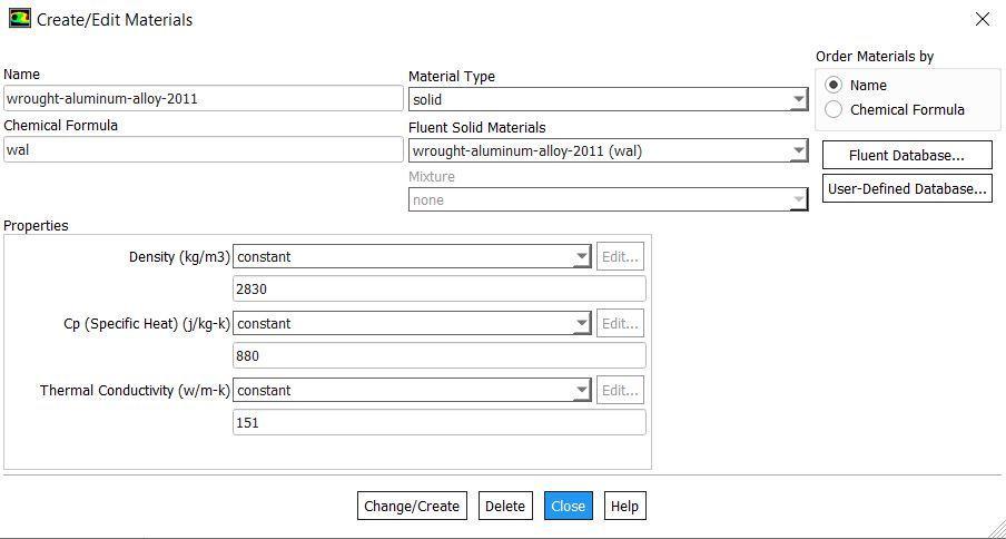
CAD Modelling


Volume: 07 Issue: 10 | Oct 2020 www.irjet.net p-ISSN: 2395-0072
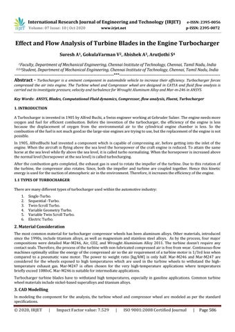
3.1 Modelling of Compressor Wheel
Advertisement
The solid model is designed in the CAD software CATIA, which is owned by the Dassault System. The impeller of the turbocharger we designed is a shaft outer diameter of 8.084mm, an inner diameter of 4.46mm and the total length is 32.4mm, and each impeller blade thickness is 0.81mm 11 blades equally aligned. These impeller blades were designed to withstand the density, thermal conductivity, viscosity, and specific heat capacity.
Fig1. Compressor Wheel
3.2 Modelling of Turbine Wheel
The impeller of the turbocharger we designed is a shaft outer diameter of 31mm, the inner diameter of 15.8mm, and the total length is 68mm, and each impeller blade thickness is 0.86mm total of 11 blades equally aligned. These impeller blades were designed to withstand the density, thermal conductivity, viscosity, and specific heat capacity.

Fig2. Turbine Wheel
4. Fluid Flow Analysis
The finished model is converted into a suitable format for the analysis software like (stp, igs, step). Here the analysis is carried out in the ANSYS Fluent (Fluid flow analysis)
Volume: 07 Issue: 10 | Oct 2020 www.irjet.net p-ISSN: 2395-0072
4.1 Analysis of Compressor Wheel
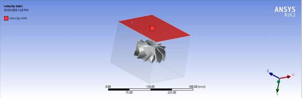
The IGS format of the turbocharger compressor wheel is imported into ANSYS Fluid Flow (Fluent) as shown in figure 3. After importing, the design file was open from Geometry Design Modeller. After that the enclosure type is defined, in this analysis box type is used.
Fig3. Model imported in the ANSYS
Fig4. Velocity conditions at the inlet
After the enclosure, meshing is performed. Here the mesh size is about 2mm and an adaptive mesh sizing. Then, the boundary conditions are given the faces to be exposed to velocity inlet and outlet, Pressure inlet, and outlet.
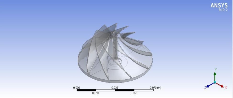
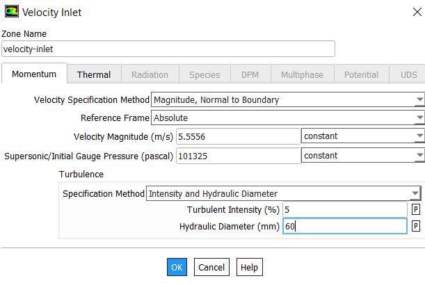
Fig6. Velocity at the inlet
Volume: 07 Issue: 10 | Oct 2020 www.irjet.net p-ISSN: 2395-0072
Here the flow type is of laminar to turbulence by Reynolds number formula. The initial value is assumed ad the 20Km/hr as the car speed and the pressure is about 1 bar, the inlet temperature is of 300K. Finally the material is applied like fluid and solid.
Fig7. Material Properties of Wrought Aluminum alloy
4.2 Analysis of Compressor Wheel
The analysis for the turbine wheel procedure is the same as the compressor wheel procedure above shown. The things change after in turbine wheel in solution setup. The condition of the turbine wheel is the same as the boundary conditions of the compressor wheel above seen. In that velocity bar, the velocity value was given as 3.375 m/s because now we considering the car moving speed of 20 km/hr according to the unit consistency of the compressor wheel to the turbine wheel. The atmospheric pressure of air is given in pressure bar 101325 Pascal then inlet temperature is taken as 693k in the thermal bar and close it. As same in the velocity-outlet dialogue box there you can just give outlet pressure that is the same as atmospheric pressure.
Fig8. Velocity at the inlet of the compressor
Volume: 07 Issue: 10 | Oct 2020 www.irjet.net p-ISSN: 2395-0072
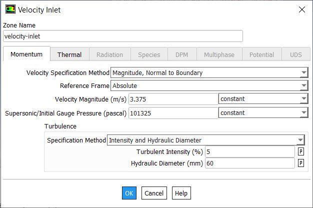
Fig9. Velocity conditions at the inlet for the compressor
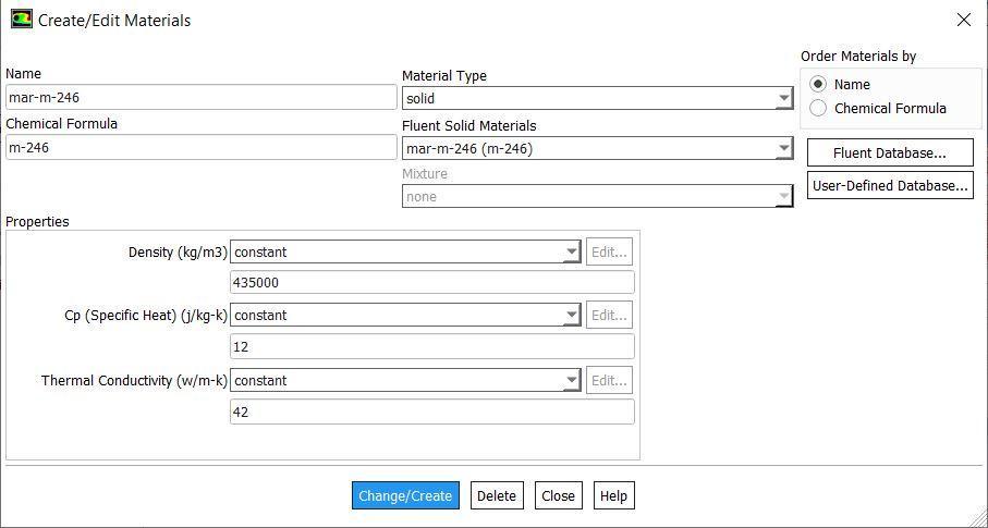
Fig7. Material Properties of Mar-m-246
5. Result and Discussion 5.1Compressor Wheel
After the analysis is completed, post-processing is done. The output values are obtained compared with each other. The figure shows a comparison between the values.
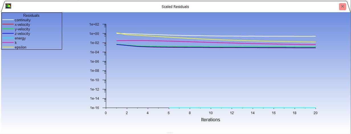
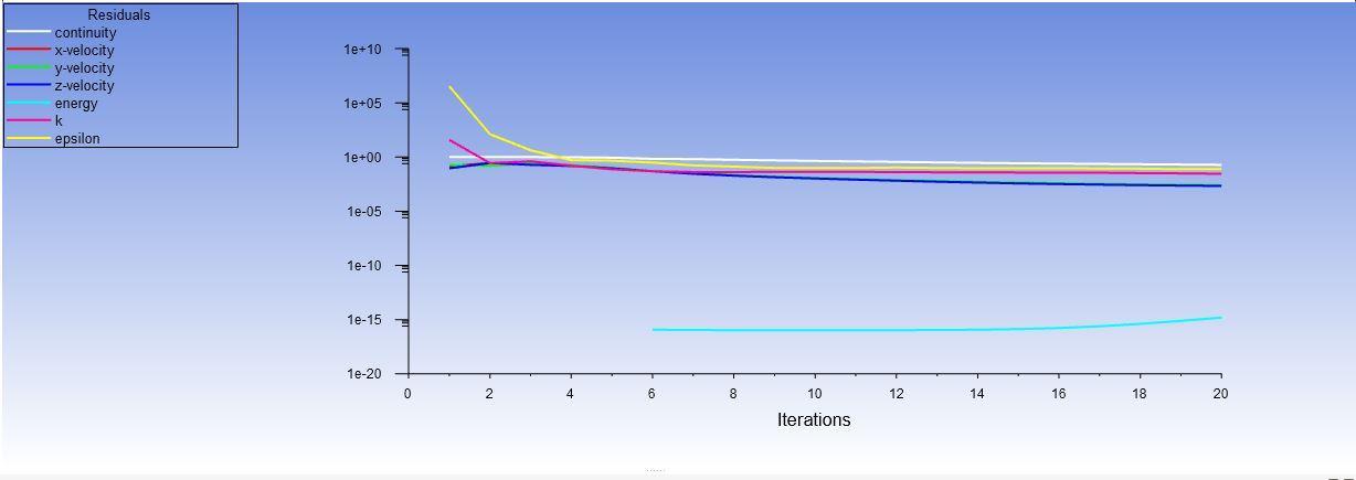
5.1.1 Scaled Residuals
Fig shows the scaled residuals on the turbocharger compressor wheel for Computational fluid dynamics and for the material wrought aluminium alloy 2011.
Fig8. Scaled Residuals of Wrought aluminum alloy
Volume: 07 Issue: 10 | Oct 2020 www.irjet.net p-ISSN: 2395-0072
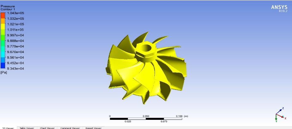
5.1.2 Pressure Contours
Figure shows pressure contour on the turbocharger compressor wheel for Computational fluid dynamics and for the material wrought aluminium alloy 2011.
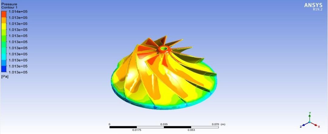
Fig9. Pressure contour
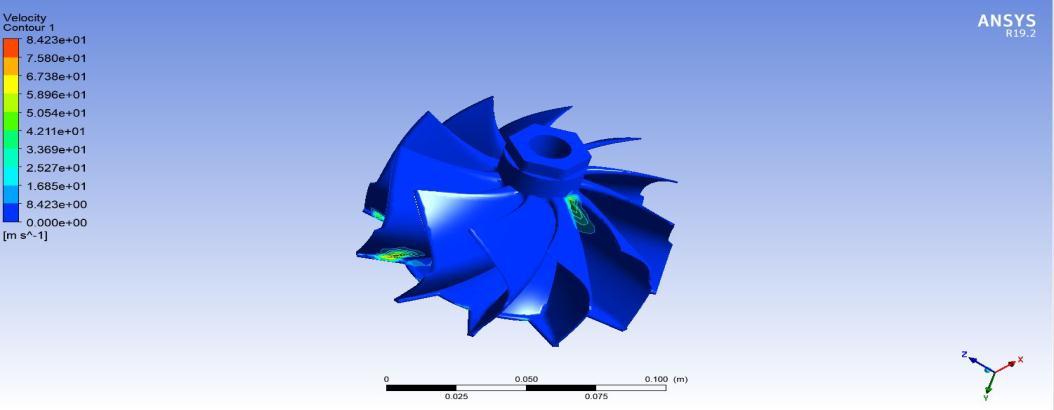
5.1.3 Velocity Contours
Figure shows the velocity contour on the turbocharger compressor wheel for Computational fluid dynamics and for the material wrought aluminium alloy 2011
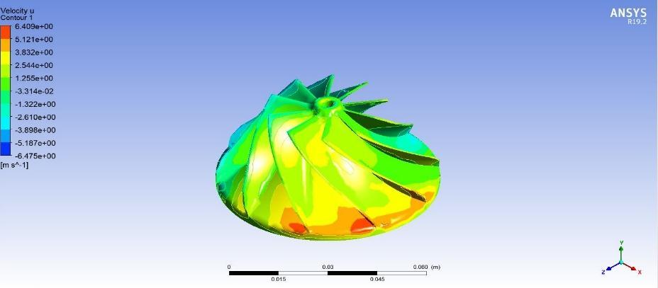
Fig10. Pressure contour
5.1.4 Turbulence Kinetic energy
Figure shows the turbulence kinetic energy on the turbocharger compressor wheel for Computational fluid dynamics and for the material wrought aluminium alloy 2011.
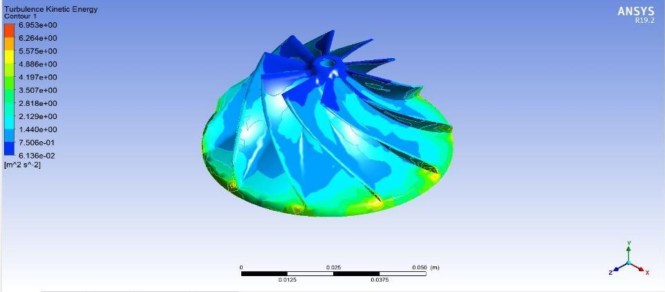
Fig11. Kinetic Energy
Volume: 07 Issue: 10 | Oct 2020 www.irjet.net p-ISSN: 2395-0072
5.2 Turbine Wheel
After the analysis is completed, post-processing is done. The output values are obtained compared with each other.
5.2.1 Scaled Residuals
Figure shows the scaled residuals on the turbocharger turbine wheel for Computational fluid dynamics and for the material Mar-m-246.
Fig12. Scaled Residuals of Mar-m-246
5.2.1 Pressure Contour
Figure shows pressure contour on the turbocharger turbine wheel for Computational fluid dynamics and for the material Mar-m-246.
Fig13. Pressure Contour of Mar-m-246
5.2.2 Velocity Contour
Figure shows the velocity contour on the turbocharger turbine wheel for Computational fluid dynamics and for the material Mar-m-246.
Fig13. Velocity Contour of Mar-m-246
Volume: 07 Issue: 10 | Oct 2020 www.irjet.net p-ISSN: 2395-0072
5.2.3 Turbulence Kinetic energy
Fig shows the turbulence kinetic energy on the turbocharger compressor wheel for Computational fluid dynamics and for the material Mar-m-246.
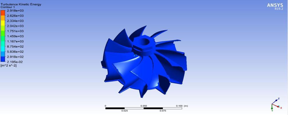
Fig14. Kinetic Energy
Table -1. Comparison between the results
Parameters
Pressure
Wrought Aluminum Alloy Mar-m-246
101356 Pa 104326 Pa
Velocity 9.56254 m/s
Velocity U Velocity V Velocity W
6.40907 m/s 2.95743 m/s 6.29250 m/s Turbulence Kinetic Energy 6.9533 m2/s2 84.2255 m/s 71.6254 m/s 43.0648 m/s 26.5760 m/s 2917.81 2/s2
6. Conclusion
From the above analysis, the outcome acquired is evident that materials wrought aluminum alloy 2011, Mar-m-246 are best to use in the turbocharger compressor wheel and turbine wheel respectively. The study is carried out in the Ansys fluent software, and the modeling is done by the Catia software. The analysis provides that it is the best combination to apply the material.
REFERENCES
1. N. Sathishkumar1 , P. Premkumar2 , A. Ruskin Bruce3 , K. Pravinkumar4 , P.L. Sudharsan5 "Design and analysis of a impeller of a Turbocharger"International journal of research and review volume.7, Issue:4 April 2020 E-ISSN: 2349-9788; P-ISSN: 2454-2237 2. D. Ramesh kumar, B. Shanmugasundaram, P. Mohanraj, "Design and Analysis of Turbocharger Impeller in Diesel
Engine" International Journal of advanced mechanical and mechanics Engineering, 2017. 3. Watson, N.and Janota , M.S., 1982, "Turbocharging the Internal Combustion Engine", Wiley, New York 4. Liu, Shujie, et al."FATIUGE life assessment of centrifugal compressor impeller based on FEA" Engineering Failure analysis 60(2016): 383-390 5. B.P.Terani, Dr. K.S.Badarinarayan, Prakasha.A., “Stability Analysis of Turbocharger Impeller: A Review”
International Research Journal of Engineering and Technology (IRJET), 2015. 6. Seiichi Ibaraki, Tetsuya Matsuo, Keiichi Shiraishi, KoichiroImakiire, “Design optimization of Turbocharger
Compressor for High pressure Turbocharged Diesel engine” Conseil International DESMachines A combustion, 2013. 7. Alsaeed, A. A., 2005, “Dynamic Stability Evaluation of an Automotive Turbocharger Rotor- Bearing System,” M.S.
Thesis, Virginia Tech Libraries, Blacksburg, VA.