

ICC-ES Evaluation Report
ESR-1790
Reissued September 2025 This report also contains: - CA Supplement
Subject to renewal September 2026
ICC-ES Evaluation Reports are not to be construed as representing aesthetics or any other attributes not specifically addressed, nor are they to be construed as an endorsement of the subject of the report or a recommendation for its use. There is no warranty by ICC Evaluation Service, LLC, express or implied, as to any finding or other matter in this report, or as to any product covered by the report.
Copyright © 2025 ICC Evaluation Service, LLC. All rights reserved.
DIVISION: 07 00 00 — THERMAL AND MOISTURE PROTECTION
Section: 07 31 16 — Metal Shingles
Section: 07 41 13 — Metal Roof Panels
REPORT HOLDER:
INTERLOCK ROOFING LTD.
ADDITIONAL LISTEE: FUTURE ROOF INC.
1.0 EVALUATION SCOPE
1.1 Compliance with the following codes:
EVALUATION SUBJECT: ROOF PANELS: SHAKE AND HIDDEN FASTENER TILE
ROOF SHINGLES: SHINGLE AND DIAMOND
2021, 2018, 2015, 2012 and 2009 International Building Code® (IBC)
2021, 2018, 2015, 2012 and 2009 International Residential Code® (IRC)
Properties evaluated:
Roof covering fire classification
Wind uplift resistance
Weather resistance
1.2 Evaluation to the following green code:
2025 and 2022 California Green Building Standards Code (CALGreen), Title 24, Part 11
Attributes verified:
See Section 2.0
2.0 USES

Steel and aluminum roof panels and shingles comply with IBC Section 1507.5 and IRC Section R905.4. Except when installed with self-adhered roof underlayment, the panels and shingles are classified as Class A or Class B roof coverings on new and over existing roofs, when installed in accordance with Section 4.4 of this report.
The attributes of the roofing panels and shingles have been verified as conforming to the provisions of CALGreen Section A5.406.1.2 for reduced maintenance. Note that decisions on compliance for those areas rest with the user of this report. The user is advised of the project-specific provisions that may be contingent upon meeting specific conditions, and the verification of those conditions is outside the scope of this report. These codes or standards often provide supplemental information as guidance.


3.0 DESCRIPTION
3.1 Roofing Panels and Shingles:
3.1.1 Aluminum Shingle and Diamond: The Shingle and Diamond aluminum roof shingles are cold-pressformed from 3105-H24 aluminum alloy complying with ASTM B209. The base-metal thickness of the aluminum is 0.019 inch (0.483 mm), and the total thickness of the coated aluminum is 0.0205 inch (0.521 mm). Shingle measure 10.37 inches long (263 mm) by 18.19 inches (462 mm) and have formed edges that act as interlocking seals with adjacent shingles. The aluminum Shingle has an installed weight of 0.41 psf (2.0 kg/m2). The Shingle may have a variety of patterns (slate, cedar, smooth or woodgrain) press-formed into the surface.
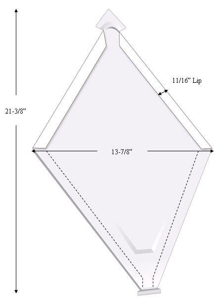
The Diamond roof shingle measures 13.875 inches (352 mm) by 21.375 inches (543 mm). The sides of each Diamond shingle incorporate formed edges that act as interlocks with adjacent diamonds. The aluminum Diamond has an installed weight of 0.41 psf (2.0 kg/m2). See Figure 1 for shingle profile.
3.1.2 Aluminum Shake and Hidden Fastener Tile Panels: The Shake and Hidden Fastener Tile aluminum roofing panels are cold-press-formed from 3003-H24 or 3105-H24 aluminum alloy complying with ASTM B209. The base-metal thickness of the aluminum is 0.0276 inch (0.701 mm), and the total thickness of the coated aluminum is 0.029 inch (0.737 mm).
The overall panel size of the Shake panel is 131/2 inches by 50 inches (343 mm by 1270 mm), and the installed exposure is 121/2 inches by 47 inches (317.5 mm by 1194 mm). The right side of each panel incorporates a 3-inch-wide (76.2 mm) side lap. The panels consist of six modules of varying widths by 121/2 inches long (317.5 mm). The panels have formed edges on the top and bottom edges of the panel that interlock when installed. The installed weight of the Shake aluminum roofing panels is approximately 0.58 psf (2.83 kg/m2). See Figure 2 for panel profile.
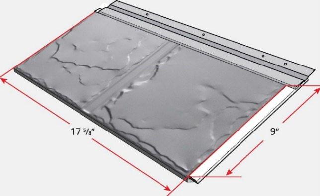
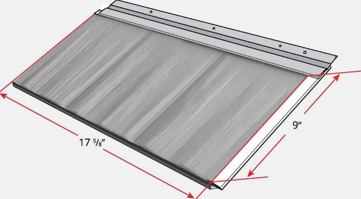
The Hidden Fastener Tile panel measures 211/2 inches (546 mm) wide with an installed exposure of 18 inches (457 mm). The panels consist of two modules, each 9 inches (229 mm) wide and 15 inches (381 mm) long, with panel lengths from 161/4 inches to 911/4 inches (413 mm to 2318 mm). Hidden Fastener Tile has an installed weight of 0.59 psf (2.88 kg/m2) for aluminum. See Figure 3 for the profile.
3.1.3 Steel Shingle and Diamond: The Steel Shingle and Diamond are cold-press-formed from sheet steel complying with ASTM A653, SS, Grade 33, and having a G90 galvanized coating or with ASTM A792 AZ50 Grade 33. The total thickness of the galvanized steel is 0.0140 inch (0.356 mm), and the total G90 galvanized thickness is 0.0015 inch (0.038 mm). The Steel Shingle, Slate and Diamond shingles are cold-press-formed into the same shape and dimensions as the Aluminum Shingle, Slate and Diamond shingles, respectively. The installed weight of the Steel Shingle is 0.86 psf (4.2 kg/m2). The installed weight of the steel Diamond shingle is 0.85 psf (4.2 kg/m2). The Shingle may have a variety of patterns (slate, cedar, smooth or woodgrain) pressformed into the surface.
3.1.4 Steel Shake and Hidden Fastener Tile Panels: The Shake and Hidden Fastener Tile steel roofing panels are cold-press-formed from sheet steel complying with ASTM A653, SS, Grade 33, and have a G90 galvanized coating or with ASTM A792 AZ50 Grade 33. The total thickness of the galvanized steel is 0.0190 inch (0.483 mm), and the total G90 galvanized coating thickness is 0.0015 inch (0.038 mm). The steel Shake and Tile panels are cold-press-formed into the same shape and dimensions as the aluminum Shake and Tile panels. The installed weight of the steel Shake roofing panels is approximately 1.16 psf (5.66 kg/m2). The installed weight of the steel Tile roofing panels is approximately 1.04 psf (5.07 kg/m2). The installed weight of the steel Hidden Fastener Tile is 1.16 psf (5.66 kg/m2). See Figure 2 for panel profiles.
3.1.5 Accessories: The eave starter, gable and collar trim, and ridge and hip caps are manufactured of the same steel and aluminum materials and with the same gage thicknesses and finishes as described above, except for the aluminum Hidden Fastener Tile and Tile gable trim and ridge cap, which are manufactured from aluminum alloy 5182 H0, having a minimum base thickness of 0.022 inch (0.559 mm).
3.1.6 Aluminum and Steel Roof Coating: The panels are coated with a fluorocarbon paint to a minimum thickness of 1.0 mil (0.0254 mm) on the top exterior surface. The panels are painted to a minimum thickness of 0.5 mil (0.0127 mm) on the bottom surface.
3.2 Fasteners: Fasteners must be installed as required in Tables 1 through 3 of this report. The fasteners must penetrate the sheathing a minimum of 1/2 inch (12.7 mm). The fasteners are supplied by Interlock Roofing Ltd.
Fasteners for the aluminum Shingle and Diamond shingles specified in Table 1, and as an alternative for aluminum Shake panels specified in Table 2, are aluminum ring shank nails having a 0.155-inch-diameter (3.94 m) shank and a 1/2-inch-diameter (12.7 mm) head.
Fasteners for the steel Shingle and Diamond shingles specified in Table 1, and as an alternative for steel Shake panels specified in Table 2, are hot-dipped galvanized ring shank steel nails having a 0.155-inch- diameter (3.94 mm) shank and a ½-inch-diameter (12.7 mm) head.
Fasteners for aluminum Shake Panels specified in Table 2, are aluminum ring shank nails having a 0.144-inch-diameter (3.66 m) shank and a 1/2-inch-diameter (12.7 mm) head.
Fasteners for steel Shake panels specified in Table 2, are hot-dipped galvanized ring shank steel nails having a 0.135-inch-diameter (3.43 mm) shank and a 3/8-inch-diameter (9.52 mm) head.
Fasteners for aluminum Hidden Fastener Tile, and as alternative fasteners for aluminum Shake panels, specified in Table 3, are No. 10 stainless steel screws [0.155 inch diameter shank (3.94 mm)], 1/4-inch hex head (6.4 mm), having both a 0.59-inch (15 mm) stainless steel washer and a butyl rubber washer.
Fasteners for steel Hidden Fastener Tile specified in Table 3, and as alternative fasteners for steel Shake panels specified in Table 2, are No. 10 galvanized steel screws [0.155 inch diameter shank (3.94 mm)], 1/4-inch-diameter head (6.4 mm), having both a 0.47-inch (12 mm) galvanized steel washer and a butyl rubber washer.
3.3 Underlayment:
Under the 2021 and 2018 IBC and IRC, underlayment must comply with IBC Sections 1507.1.1 and 1507.5.3 or IRC Sections R905.1.1 and R905.4.3, as applicable. Under the 2015, 2012 and 2009 IBC and IRC, underlayment must comply with IBC Section 1507.5.3 or IRC Section R905.4.3, as applicable. On construction permitted to be nonclassified roofing, mechanically attached and self-adhered roof underlayments may be used that are named in an ICC-ES evaluation report as alternatives to the ASTM D226, Type I and Type II, underlayments specified in IBC Chapter 15 and IRC Chapter 9.
4.0 INSTALLATION
4.1 Roof Slope:
Shingle and Diamond must be installed on a minimum roof slope of 3:12 (25-percent) when installed with a code-compliant self-adhered roof underlayment or a minimum roof slope of 5:12 (41-percent) when installed with a code-compliant mechanically attached roof underlayment. Shake and Hidden Fastener Tile must be installed on a minimum roof slope of 3:12 (25-percent) when installed with a code-compliant self-adhered roof underlayment or a minimum roof slope of 4:12 (33-percent) when installed with a code-compliant mechanically attached roof underlayment.
4.2 Installation—New Construction:
Roofing panels and shingles must be installed on minimum 15/32-inch-thick (11.9 mm) plywood sheathing complying with the applicable code. Delta Hidden Fastener Tile may also be installed over spaced sheathing as indicated in Section 4.7. Underlayment, as described in Section 3.3 of this report, must be applied per the applicable code.
Shingle and Diamond shingles are installed with one nail in the nailing strip. Additional clips and nails may be required in accordance with local wind conditions, based on the design uplift wind pressure as determined in accordance with IBC Section 1609.5.1 and IRC Section R301.2.1. See Table 1. The first row of shingles hook into the lip of the eave starter flashing. The formed shingle edges interlock with the adjacent shingles.
Shake panels must be placed over the underlayment and must start at the eave. The front of the panels in the first course must be hooked into the lip of the eave starter flashing. The panels overlap on the right side of each panel by 3 inches (76.2 mm). The rear of each panel must be fastened to the sheathing with clips and fasteners as described in Table 2. The clips must be equally spaced along the panel. The next course must hook into the lip of the course below it.
Hidden Fastener panels interlock and are installed from right to left and are fastened on the left to the sheathing using fasteners described in Section 3.2, using the fastening pattern described in Table 3
Panels must be cut and formed at valleys.
5.0
Valley flashings must comply and be installed in accordance with IBC Section 1507.5.7 or IRC Section R905.4.6. Other flashing must comply with IBC Section 1503.2.1 or IRC Section R903.2.1. Valley flashing is attached with nails, installed four per side every 10 feet (3048 mm). Valley flashing end laps must be a minimum of 412 inches (102 mm). The valley flashing must have one layer of underlayment, at least 36 inches (914 mm) wide, directly under the full flashing length.
Penetrations through the roof covering must be flashed by installing standard roof jacks which drain over the panel immediately below the penetration. The lower edge of the panel containing the jack must be notch-cutout to allow water drainage from the jack to the top of the panel below. Tile and Hidden Fastener Tile panels must be flashed with prefabricated roof flashings for pipe penetrations named in an ICC-ES evaluation report. Openings through the roofing for air vents must be adequately weatherproofed and supported by additional blocking or roof framing as necessary in accordance with the manufacturer’s published installation instructions.
4.3 Installation Reroofing:
The existing roof covering must be completely removed, and the panels installed in accordance with Section 4.2 of this report, except over asphalt shingle roofs as described in this section. The panels may be installed over existing spaced sheathing provided the space between boards is filled with lumber as necessary to provide a base for fastening. The fill lumber shall be of the same thickness as the existing spaced sheathing. The Shingle, Diamond, Shake and Tile roofing panels may be installed over existing asphalt shingle roofs, provided the roof slope complies with Section 4.1 of this report and the requirements of 2021, 2018 and 2015 IBC Section 1511, 2012 and 2009 IBC Section 1510 or 2021 and 2018 IRC Section R908, or 2015, 2012 and 2009 IRC Section R907 are met. The panels must be fastened through the existing roof covering to the roof sheathing in the same manner as described in Section 4.2, with screws or nails of sufficient length to penetrate through the sheathing a minimum of 1/2 inch (12.7 mm). Existing flashings must be removed and replaced with new flashing, vents, valleys and chimneys in accordance with this report and the applicable code.
4.4 Fire Classification:
Shingles and panels installed in accordance with Section 4.2 or 4.3 of this report are classified as Class A or Class B roof assemblies under IBC Sections 1505.2 and 1505.3 and IRC Section R902.1 when the roof assemblies incorporate GAF Versashield® Fire-Resistant Roof Deck Protection and are installed in accordance with ICC-ES evaluation report ESR-2053. When installed with a self-adhered roof underlayment, the roofing assembly is a nonclassified roof covering.
4.5 Wind Resistance:
Shake, Shingle, Diamond, and Hidden Fastener Tile installed in accordance with Section 4.0, using the fasteners, clips and roof deck specified in Tables 1, 2 and 3 are acceptable on any portion of the roof having the maximum allowable uplift loads specified in the tables. The design wind pressure must be determined in accordance with IBC Section 1609.5 and IRC Section R301.2.1.
4.6 Ice Barrier in Severe Climate Areas:
Under the 2021 and 2018 IBC and IRC, an ice barrier must be provided in accordance with IBC Section 1507.1.2 or IRC Sections R905.1.2 and R905.4.3.1, as applicable. Under the 2015 IBC and IRC, an ice barrier must be provided in accordance with IBC Section 1507.5.4 or IRC Sections R905.1.2 and R905.4.3.1, as applicable. Under the 2012 and 2009 IBC or IRC, an ice barrier must be provided in accordance with IBC Section 1507.5.4 or IRC Section R905.4.3.1, as applicable.
4.7 Positive Loads:
Positive (gravity) loads are limited to the adequacy of the supporting structural framing and sheathing except when installation is on spaced sheathing. When installation is on spaced sheathing, the Hidden Fastener Tile aluminum panels are limited to the lesser of the adequacy of the structural framing and sheathing or the allowable panel load. The Hidden Fastener Tile steel and aluminum panels have an allowable load of 52 psf (2.5 kPa) when the supporting framing is spaced at a maximum of 15 inches (381 mm) on center.
CONDITIONS OF USE:
The Roofing Panels and Roof Shingles described in this report comply with, or are suitable alternatives to what is specified in, those codes listed in Section 1.0 of this report, subject to the following conditions:
5.1 The panels are manufactured, identified, and installed in accordance with this report, the applicable code and the report holder’s published installation instructions. In the event of a conflict between this report and the report holder’s installation instructions, this report governs.
6.0 EVIDENCE SUBMITTED
Data in accordance with the ICC-ES Acceptance Criteria for Metal Roof Coverings (AC166), dated February 2021.
7.0 IDENTIFICATION
7.1 The ICC-ES mark of conformity, electronic labeling, or the evaluation report number (ICC-ES ESR-1790) along with the name, registered trademark, or registered logo of the report holder [and/or listee] must be included in the product label.
7.2 In addition, a label bearing the report holder’s name (Interlocking Roofing Ltd.) or additional listee’s name (Future Roof Inc) and address, the product name, and the evaluation report number (ESR-1790) is affixed to each pallet or bundle.
7.3 The report holder’s contact information is the following:
INTERLOCK ROOFING LTD.
9969 RIVER WAY DELTA, BRITISH COLUMBIA V4G 1M8 CANADA (604) 953-1000
7.4 The Additional Listee's contact information is the following: FUTURE ROOF INC. 9969 RIVER WAY DELTA, BRITISH COLUMBIA V4G 1M8 CANADA (800) 959-8089 www.futureroof.com info@futureroof.com
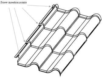
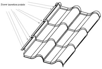
3 nails per panel equally spaced in nail strip with two clips fastened with 2 nails per clip
For SI: 1psf = 0.04788 kPa.
1See Section 3.2 for description of fasteners.
SLATE SHINGLE
CEDAR SHINGLE
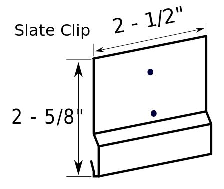
FIGURE 1 SHINGLES AND CLIP
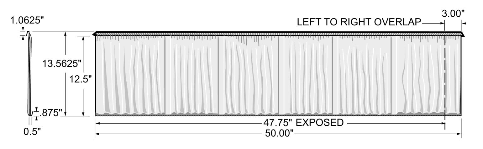
FIGURE 2 SHAKE
Minimum 15/32-inch APA rated Plywood
Aluminum or Steel
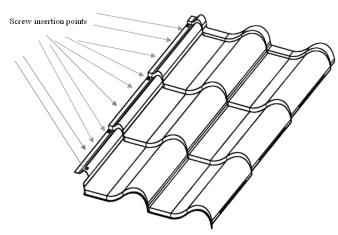
Minimum 21/2 inch long at left edge and 3-inch long at bottom right Stainless steel screws for aluminum panels as described in Section 3.2 or Galvanized Steel screw for steel panels as described in Section 3.2
PATTERN
FIGURE 3 HIDDEN FASTENER TILE FASTENING PATTERN
Reissued September 2025 This report is subject to renewal September 2026.
www.icc-es.org | (800) 423-6587 | (562) 699-0543 A Subsidiary of the International Code Council ®
DIVISION: 07 00 00—THERMAL AND MOISTURE PROTECTION
Section: 07 31 16—Metal Shingles
Section: 07 41 13—Metal Roof Panels
REPORT HOLDER:
INTERLOCK ROOFING LTD.
ADDITIONAL LISTEE:
INTERLOCK ROOFING LTD.
EVALUATION SUBJECT:
ROOF PANELS: SHAKE AND HIDDEN FASTENER TILE ROOF SHINGLES: SHINGLE AND DIAMOND
1.0 REPORT PURPOSE AND SCOPE
Purpose:
The purpose of this evaluation report supplement is to indicate that Roof Panels: Shake and Hidden Fastener Tile and Roof Shingles: Shingle and Diamond, described in ICC-ES evaluation report ESR-1790, have also been evaluated for compliance with the codes noted below.
Applicable code edition(s):
2022 California Building Code (CBC)
For evaluation of applicable Chapters adopted by the California Office of Statewide Health Planning and Development (OSHPD) AKA: California Department of Health Care Access and Information (HCAI) and the Division of State Architect (DSA), see Sections 2.1.1 and 2.1.2 below.
2022 California Residential Code (CRC)
2.0 CONCLUSIONS
2.1 CBC:
The Roof Panels: Shake and Hidden Fastener Tile and Roof Shingles: Shingle and Diamond, described in Sections 2.0 through 7.0 of the evaluation report ESR-1790, may be used where the CBC requires a Class A roof covering complying with CBC Section 1505.1.1 or a Class C roof covering complying with CBC Section 1505.1.2, provided the design and installation are in accordance with the 2021 International Building Code® (IBC) provisions noted in the evaluation, as applicable.
The products have not been evaluated under Chapter 7A for use in the exterior design and construction of new buildings located in a Fire Hazard Severity Zone within State Responsibility Areas or any Wildland–Urban Interface Fire Area.
2.1.1 OSHPD:
The applicable OSHPD Sections and Chapters of the CBC are beyond the scope of this supplement.
2.1.2 DSA:
The applicable DSA Sections and Chapters of the CBC are beyond the scope of this supplement.
2.2 CRC:
The Roof Panels: Shake and Hidden Fastener Tile and Roof Shingles: Shingle and Diamond, described in Sections 2.0 through 7.0 of the evaluation report ESR-1790, may be used where the CRC requires a Class A roof covering complying with CRC Section R902.1.1 or a Class C roof covering complying with CRC Section 902.1.2, provided the design and installation are in accordance with the 2021 International Residential Code® (IRC) provisions noted in the evaluation report and the additional requirements of CRC Section R905.4, as applicable.


The products have not been evaluated under CRC Section R337 for use in the exterior design and construction of new buildings located in a Fire Hazard Severity Zone within State Responsibility Areas or any Wildland –Urban Interface Fire Area. The products recognized in this supplement have not been evaluated for compliance with the International Wildland–Urban Interface Code® This supplement expires concurrently with the evaluation report, reissued September 2025.