

FOR THE MIM, CIM AND SINTER-BASED AM INDUSTRIES INTERNATIONAL IN THIS ISSUE EVALUATING MIM AS A GREEN TECHNOLOGY SIMULATING A SINTERING FURNACE A HITCHHIKER’S GUIDE TO METAL FFF www.pim-international.com Published by Inovar Communications Ltd VOL. 17. NO. 2 SUMMER 2023
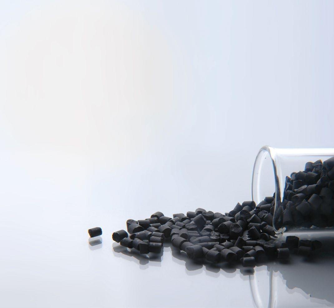
MIM/PIM FEEDSTOCKS
• At RYER, all our feedstocks are manufactured to the highest level of quality, with excellent batch-to-batch repeatability.
• RYER is the ONLY commercially available feedstock manufacturer to offer all five debind methods.
• RYER offers the largest material selections of any commercially available feedstock manufacturer.
• RYER offers technical support for feedstock selection, injection molding, debinding and sintering.
CataMIM®
• A direct replacement for all current commercially available catalytic debind feedstocks
• Improved flow
• Stronger green and brown parts
• More materials available and better surface finish
• Custom scale-up factors available
• Faster cycle times
• 65°C / 150°F mold temperature
AquaMIM®
• Water Debind
• Custom scale-up factors available
• Large selection of available materials
SolvMIM®
• Solvent, Super Critical Fluid Extraction (SFE) or Thermal Debind methods
• Hundreds of materials available
• Custom scale-up factors available
RYER, Inc. | 42625 Rio Nedo Unit B | Temecula, CA 92590 | USA | Tel: +1 951 296 2203 Email: dave@ryerinc.com | www.ryerinc.com www.ryerinc.com
Publisher & Editorial Offices
Inovar Communications Ltd

11 Park Plaza
Battlefield Enterprise Park Shrewsbury SY1 3AF
United Kingdom
Tel: +44 (0)1743 469909 www.pim-international.com
Managing Director & Editor
Nick Williams, nick@inovar-communications.com
Group News Editor
Paul Whittaker, paul@inovar-communications.com
Advertising Sales Director
Jon Craxford, Advertising Sales Director Tel: +44 (0)207 1939 749 jon@inovar-communications.com
Assistant Editor
Amelia Gregory, amelia@inovar-communications.com
Assistant News Editor
Charlie Hopson-VandenBos charlie@inovar-communications.com
Senior Digital Marketer

Swetha Akshita, swetha@inovar-communications.com
Digital Marketer
Mulltisa Moung, mulltisa@inovar-communications.com
Production Manager
Hugo Ribeiro, hugo@inovar-communications.com
Operations & Partnerships Manager
Merryl Le Roux, merryl@inovar-communications.com
Office & Accounts Manager
Jo Sheffield, jo@inovar-communications.com
Technical Consultant
Dr Martin McMahon
Consulting Editors
Prof Randall M German
Former Professor of Mechanical Engineering, San Diego State University, USA
Dr Yoshiyuki Kato
Kato Professional Engineer Office, Yokohama, Japan
Professor Dr Frank Petzoldt
Ingenieurbüro Dr. Petzoldt, Geestland, Germany
Dr David Whittaker
DWA Consulting, Wolverhampton, UK
Bernard Williams
Consultant, Shrewsbury, UK
Subscriptions
PIM International is published on a quarterly basis as either a free digital publication or via a paid print subscription. The annual print subscription charge for four issues is £150 including shipping.

Accuracy of contents
Whilst every effort has been made to ensure the accuracy of the information in this publication, the publisher accepts no responsibility for errors or omissions or for any consequences arising there from. Inovar Communications Ltd cannot be held responsible for views or claims expressed by contributors or advertisers, which are not necessarily those of the publisher.
Advertisements
Although all advertising material is expected to conform to ethical standards, inclusion in this publication does not constitute a guarantee or endorsement of the quality or value of such product or of the claims made by its manufacturer.
Reproduction, storage and usage
Single photocopies of articles may be made for personal use in accordance with national copyright laws. All rights reserved. Except as outlined above, no part of this publication may be reproduced or transmitted in any form or by any means, electronic, photocopying or otherwise, without prior
permission of the publisher and copyright owner.
Design and production
Inovar Communications Ltd.
ISSN 2050-9693 (Print edition)
ISSN 2050-9707 (Online edition)
© 2023 Inovar Communications Ltd.
The competitive advantage of MIM’s green credentials
Metal Injection Moulding has for decades been considered a green technology. As a high efficiency manufacturing process, often producing parts to net shape and with minimal material waste, the very things that make MIM green also make MIM competitive.
For many, the comfort of this knowledge was ‘good enough’ not to push further. Global circumstances, however, from climate change to higher energy costs and raw materials supply concerns, are now prompting MIM producers around the world to take a closer look at where further improvements to MIM’s sustainability can be made.
What is clear is that to fully understand the environmental impact of the MIM process, a detailed and methodical life cycle analysis has to be carried out - involving the entire process chain. What this means for MIM producers is explored in detail in our lead article by Dr Frank Petzoldt and Dr Sebastian Boris Hein ( page 61 ).
Whilst the outcome of this work will without doubt lead to both reduced costs and a reduced carbon footprint, being able to quantify the environmental impact of specific MIM parts compared to alternative processes – especially at the point of tendering for contracts – will become ever more valuable.
With the Yokohama World PM2024 congress on the horizon, perhaps this meeting point of the global MIM industry will be an opportunity to meet and drive forward progress on this topic with a global effort.
Nick Williams Managing Director & Editor
Cover image
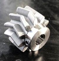
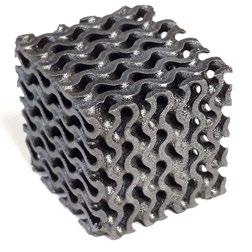
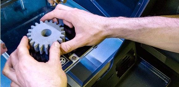
A sintered component produced by low-cost filament-based Material Extrusion (MEX) technology (Courtesy Sascha Lenze)
GETPDF SUMMER 2023 PIM INTERNATIONAL
3 FOR MIM, CIM AND SINTER-BASED AM
The Shop System™
Now offering an expanded lineup of the world’s best-selling metal binder jet machine
Shop System
The original plug-and-play solution from Desktop Metal to get started 3D printing metal parts fast - no prior binder jetting experience required
Everything you need at an affordable price. Intuitive software drives a complete system, from 3D printer and depowdering station to an industrial-grade furnace
Shop System+
A more economic solution for high-power customers to reduce operating costs with locked in discounts on DM powder and binders
Lower the cost of additive operations and improve part costs to drive faster ROI with the same plug-and-play experience and materials as the base package
Shop System Pro
A more flexible solution for customers with powder metallurgy experience that unlocks custom printing and sintering process parameters
Expand beyond DM-supplied alloys to new applications or reduce operating costs through the use of third-party or proprietary powders
Learn more by downloading the Shop System specifications teamdm.com/ShopPackages
NEW PACKAGES AVAILABLE
61 Evaluating Metal Injection Moulding as a green production technology
Sustainability is a topic that concerns all of us, from individuals to societies and industries. As we face increasingly difficult environmental challenges, discussions about sustainability and our contribution towards it are ongoing in many areas of our daily lives. This is, of course, also true for the Metal Injection Moulding industry. Whilst MIM is already considered a green technology compared to alternative processes, there are still considerable opportunities for improvement that can be identified through life cycle assessment and carbon footprint analysis.
Dr Frank Petzoldt and Dr Sebastian Boris Hein consider the complex task of evaluating MIM as a green technology within this context. >>>

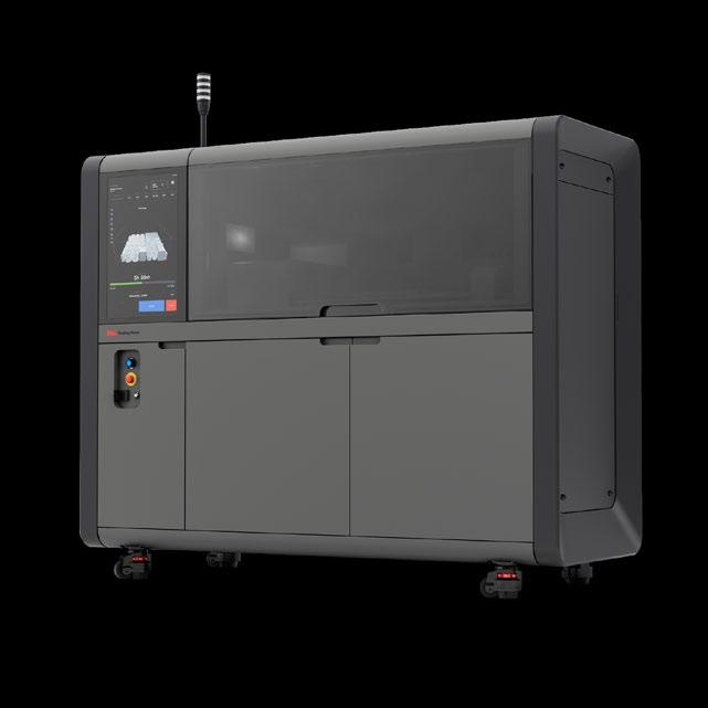
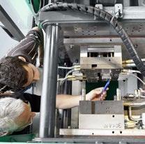
71 Simulating sintering furnaces: A ‘check-and-act’ solution to optimse MIM and sinter-based AM production
The consistent high quality of sintered parts produced by Metal Injection Moulding, or AM processes such as Binder Jetting, can only be achieved with stable manufacturing conditions. Inhomogeneous and transient temperatures in sintering furnaces are one area where variability can be difficult to manage. This article outlines how simulation can lead to an optimal set up for the sintering process – or at least a best compromise – via the assessment of many possible process variations.
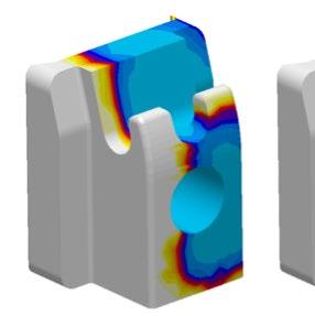
Dr Götz Hartmann and Dr Wilfried Schäfer, MAGMA GmbH, and Dr Jesper Thorborg, Technical University of Denmark, share the results of recent research. >>>

GETPDF SUMMER 2023 PIM INTERNATIONAL VOL. 17 NO. 2 © 2023 INOVAR COMMUNICATIONS LTD 5 Summer 2023 9 77 107 85 14
09 Industry news >>> 111 Advertisers’ index & buyer’s guide >>> 114 Events guide >>> Regular features...
Quality, Experience and Customer Relationships


Elnik’s innovations and experiences in all areas of temperature and atmosphere management have led us to become the leaders for the Batch-based Debind and Sinter equipment industry. We have applied these core competencies across a wide variety of industries through our 50 year history and look forward to the emergence of new technologies that will continue to drive demand for new innovative products.
We offer:
First Stage Debind Equipment (Catalytic, Solvent, Water)
Debind & Sinter Furnaces (All Metal or Graphite)


Elnik’s experienced team is driven to be the only partner you need for all your MIM and Metal AM equipment for 2022 and beyond.

107 Commerce Road | Cedar Grove, NJ 07009 USA | +1 973.239.6066 | elnik.com
We are driven by these values.
81 Don’t panic! A hitchhiker’s guide to metal Fused Filament Fabrication (FFF)
This is a story from what once looked like the edge of the metal Additive Manufacturing universe. A decade ago, the idea of a MIM feedstock-like filament for Fused Filament Fabrication (FFF) was the stuff of beer talk, but then things started to happen. Through a Facebook group called ‘FFF Metal 3D printing’ I discovered what felt like an underground community, driven by the seemingly impossible prospect of ‘printing metal’ on a shoestring budget. Amongst the dramatic images of failed builds and small piles of melted steel, posts by Sascha Lenze stood out.
Here, he shares the story of L.B. Bohle Maschinen und Verfahren GmbH’s journey towards the Material Extrusion (MEX) of metal-containing filaments for industrial applications. Welcome to the new frontier! >>>
91 MIM2023: Industry insights from the International Conference on Injection Moulding of Metals, Ceramics and Carbides

The 2023 International Conference on Injection Moulding of Metals, Ceramics and Carbides (MIM2023), organised by the Metal Powder Industries Federation (MPIF)’s Metal Injection Molding Association (MIMA), was held in Costa Mesa, California, USA, from February 27 to March 1, 2023. As well as being the annual meeting point of the US MIM community, the event attracts an international audience and has broadened in scope to include sinterbased Additive Manufacturing processes. Dr Animesh Bose reviews some highlights from the MIM2023 technical programme. >>>
Regular features...
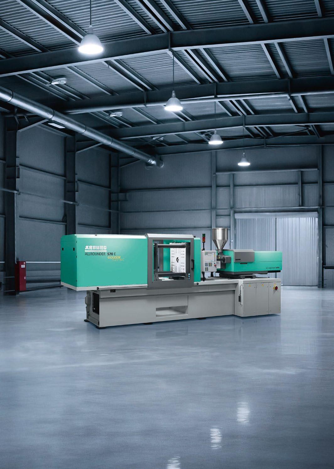
105 Greening MIM: How Arburg is supporting energy and cost reductions in injection moulding facilities
Arburg GmbH + Co KG, Lossburg, Germany, a pioneer in the use of sustainable energy in its own operations, is now leveraging that expertise to support its customers in their mission to reduce energy consumption and improve the sustainability of injection moulding operations.
Here, the company reports on its ‘Action Plan: Energy’, launched earlier this year, which has the specific goal of identifying and implementing a broad range of energy- and cost-saving opportunities. >>>
114 Events guide
View a list of upcoming events for the MIM, CIM & sinter-based AM industries. >>>
GETPDF SUMMER 2023 PIM INTERNATIONAL VOL. 17 NO. 2 © 2023 INOVAR COMMUNICATIONS LTD 7
Industry news >>>
Advertisers’ index &
09
111
buyer’s guide
Discover the leading suppliers of materials and equipment for MIM, CIM and sinter-based AM, as well as part manufacturing partners and more. >>>


Ceramic Injection Moulding shines on the new Range Rover SV
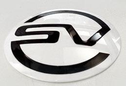
The new Range Rover SV, from Jaguar Land Rover’s Special Vehicle Operations division, will feature a number of components produced by Ceramic Injection Moulding. The CIM parts, produced by the Oechsler Group, headquartered in Ansbach, Germany, include the two-colour ceramic roundel displayed on the rear tailgate of SV models as well as the gear shifter, terrain response and volume controls.
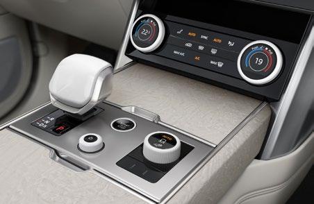
Jaguar Land Rover stated, “The New Range Rover SV is the first vehicle from Special Vehicle Operations to carry the new ceramic SV roundel, which represents the SVO team’s design and engineering passion for modern luxury, performance and capability. The roundel introduces a simplified ‘SV’ model name that will
identify all new Land Rover vehicles launched by Special Vehicle Operations in future.”
These exclusive CIM components, produced using the same process as many luxury ceramic watch cases, are precision ground after sintering to create a perfectly even surface before the components are either diamond polished or sand-blasted to achieve the desired gloss or satin finish. “The whole process takes around ten weeks, including final quality inspection by hand,” added Jaguar Land Rover.
Michael Van Der Sande, Managing Director, Special Vehicle Operations, commented, “Working with the finest materials and innovative technologies has enabled us to introduce even more luxury into every part of the New Range Rover SV. This attention to detail and
quality is evident throughout the vehicle and is symbolised by our new white ceramic SV roundel on the tailgate.”

Oechsler Group has an established reputation for the production of components by Ceramic Injection Moulding for high-end automotive applications. In recent years, the company also expanded its operations to include metal Additive Manufacturing.
www.oechsler.com
www.jaguarlandrover.com
| contents | news | events | advertisers | website | newsletter | GETPDF SUMMER 2023 PIM INTERNATIONAL VOL. 17 NO. 2 © 2023 INOVAR COMMUNICATIONS LTD
9
Industry News
The CIM parts include the two-colour ceramic roundel displayed on the rear tailgate of SV models (Courtesy Jaguar Land Rover)
The gear shift, volume dial and terrain response dial are all produced using Ceramic Injection Moulding, offering a cool-to-thetouch, scratch-resistant luxury finish (Courtesy Jaguar Land Rover)
The SV roundel is produced at Oechsler using two-colour Ceramic Injection Moulding (Courtesy Oechsler)
Stratasys and Desktop Metal to merge in $1.8 billion all-stock transaction, 3D Systems eyes takeover
Stratasys Ltd and Desktop Metal, Inc, have announced a definitive agreement whereby the companies will combine in an all-stock transaction valued at approximately $1.8 billion. Together, the merger creates an Additive Manufacturing company delivering industrial metal, polymer, sand and ceramic solutions from design to mass production.
Under the terms of the agreement, which has been unanimously approved by the Boards of Directors of both companies, Desktop Metal stockholders will receive 0.123 ordinary shares of Stratasys for each share of Desktop Metal Class A common stock. This represents a value of approximately $1.88 per share of Desktop Metal Class A common stock based on the closing price of a Stratasys ordinary share of $15.26 on May 23, 2023.
Following the closing of the transaction, which is expected to occur in the fourth quarter of 2023, existing Stratasys shareholders will own approximately 59% of the combined company, and legacy Desktop Metal stockholders will own approximately 41% of the combined company, in each case, on a fully-diluted basis.
The transaction establishes an Additive Manufacturing company that is expected to be one of the largest companies in the industry, targeting $1.1 billion in 2025 revenue.
“Today is an important day in Stratasys’ evolution,” stated Dr Yoav Zeif, CEO of Stratasys. “The combination with Desktop Metal will accelerate our growth trajectory by uniting two leaders to create a premier global provider of industrial Additive Manufacturing solutions. With attractive positions across complementary product offerings, including aerospace, automotive, consumer products, healthcare and dental, as well as one of the largest and most experienced R&D teams, industry-leading go-to-market infra -
structure and a robust balance sheet, the combined company will be committed to delivering ongoing innovation while providing outstanding service to customers. We look forward to building on the complementary strengths of the combined business and leveraging the strong brand equity across the portfolio to deliver enhanced value to shareholders, customers and employees.”
“We believe this is a landmark moment for the Additive Manufacturing industry,” added Ric Fulop, co-founder, chairman and CEO of Desktop Metal. “The combination of these two great companies marks a turning point in driving the next phase of Additive Manufacturing for mass production. We are excited to complement our portfolio of production metal, sand, ceramic and dental 3D printing solutions with Stratasys’ polymer offerings. Together, we will strive to build an even more resilient offering with a diversified customer base across industries and applications in order to drive long-term sustainable growth. We look forward to combining with Stratasys to deliver profitability while driving further innovation for a larger customer base and providing expanded opportunities for our employees.”
Following the close of the transaction, Dr Zeif will lead the combined company as Chief Executive Officer together with Ric Fulop as Chairman of the Board. Upon completion of the transaction, the combined company’s Board of Directors will be comprised of eleven members, five of whom will be selected by Stratasys, and five of whom will be selected by Desktop Metal, plus Dr Zeif as CEO. Stratasys Chairman Dov Ofer will serve as lead independent director of the combined company.
The transaction also brings together complementary IP portfolios with more than 3,400 patents
and pending patent applications. Together, Stratasys and Desktop Metal have invested over $500 million in R&D over the past four fiscal years. In addition, the combined company will have one of the largest R&D and engineering teams in the industry, with over 800 scientists and engineers focused on driving innovation across a differentiated materials library.
3D Systems makes offer for Stratasys
Shortly after the merger announcement, Stratasys received an unsolicited buyout proposal from 3D Systems, headquartered in Rock Hill, South Carolina. In accordance with fiduciary duties and obligations under the all-stock merger with Desktop Metal, it was stated that Stratasys will review the non-binding proposal, however, any decisions made on the basis of the proposal would not impact the agreement with Desktop Metal.
3D Systems outlined the possible benefits of such an acquisition for shareholders and the industry. “The combination of 3D Systems and Stratasys is simply the best outcome for the shareholders of both companies,” stated Dr Jeffrey Graves, president and CEO, 3D Systems. “We feel strongly that now is the time for all parties to recognise the overwhelming logic of our two businesses coming together.”
“We are at an inflection point in our industry, and we see significant upside for our shareholders and all stakeholders by capturing the benefits of scale, enhancing investment in innovation and delivering longterm profitable growth. We know and respect the Stratasys business and the people who make it a success around the world. We are committed to creating a combined platform that enables these two great companies to serve our global customers and lead the industry with innovative technology offerings,” concluded Dr Graves.
www.stratasys.com
www.3dsystems.com
www.desktopmetal.com
10 PIM INTERNATIONAL SUMMER 2023 © 2023 INOVAR COMMUNICATIONS LTD VOL. 17 NO. 2 | contents | news | events | advertisers | website | newsletter | Industry news
CHARACTERISTICS
Plasma Quality Powder
High Sphericity
High Purity Traceability
Ti64
MIM POWDER MANUFACTURER
Tekna.com
Ta Al ALLOYS Ni ALLOYS
W
A successful, global company.
Our software has changed manufacturing technology in metal casting and polymer injection molding over the last 35 years.
Now we aim to do the same for powder metallurgy, technical ceramics and additive processes.
If you are excited to drive and push this new potential business area, if you want to work with both young guns and experienced experts, contact us!
We are looking for people who want join us, in a leading role, in a growing business sector.
If you have questions or want more information, please contact: Dr.-Ing. Götz Hartmann, Phone: +49 241 88901-405, G.Hartmann@magmasoft.de.
To learn more about MAGMA, visit www.magmasoft.de
Eyewear leader Visottica Group acquires Ideal
Visottica Group, a producer of eyewear components headquartered in Susegano, Italy, has acquired Ideal SrL, a company active in the engineering and production of small metal parts for the eyewear sector based in Quero, Italy, from parent company TechVision.
“The acquisition of a historical and strategic company for the eyewear district such as Ideal is in-line with the development plan we have been resolutely pursuing in recent years,” stated Rinaldo Montalban, Visottica Group President. “Thanks to the technical expertise, along with the considerable size of the Quero production site, we have the opportunity to better answer a constantly growing market demand. Ideal possesses highly specialised know-how enabling us to create virtuous synergies between the various companies that are part of the Visottica Group, also facilitated by the geographic proximity between the various production sites.”
“This translates into more services for our customers and partners in the eyewear sector, one we have historically presided over, but also in the greater ability to move in other directions and explore new horizons by expanding our business areas,” Montalban continued. “We continue the path of growth, with the aim of consolidating and expanding our industrial hub established on high-precision technologies, capable of satisfying the widest range of our customers’ needs.”
The addition of Ideal is part of a strategy that has enabled Visottica to expand its offering and consolidate its global leadership while maintaining a strong production presence in Italy. The group acquired 50% of Eurodecori, a company in Belluno specialising in the production and processing of Zamak (zinc alloy) parts, in 2021, and completed the acquisition of the majority of the capital of Ookii
DSB Technologies announces metal Binder Jetting prototyping service
DSB Technologies, a manufacturer of Powder Metallurgy components headquartered in Janesville, Wisconsin, USA, has announced the launch of its metal Binder Jetting (BJT) prototyping service. Through this service, customers will be able to leverage the speed and cost-efficiency of metal Additive Manufacturing to iterate designs more efficiently than conventional metalworking processes.
“DSB views this prototyping program as an important stride to educating the marketplace on the capabilities of the metal binder jet technology and helping grow product application opportunities,” stated Paul Hauck, DSB Technologies Chief Operating Officer. “We are broadening access to DSB’s experienced
and knowledgeable 3D printing design and process engineers for customers seeking to prototype and iterate their metal part designs.”
Customers can now design and produce metal Binder Jetting prototypes in two weeks or less for part sizes up to 15 cm 3 from 17-4 PH stainless steel. Prototypes of up to 5 cm 3 part size are available in four weeks or less in 316L stainless steel, M2 tool steel, and 4140 steel.
DSB Technologies has been established for over forty years and offers a wide range of metal powder-based services including press and sinter PM, Metal Injection Moulding and metal
Visottica Group has acquired Ideal Srl based in Quero, Italy (Courtesy Visottica)

– a company focused on precision micromechanics, also located in the Belluno eyewear district. Ookii holds 100% of the capital of Matrix, a leading company in the production of MIM and microfusion components. Visottica also acquired a majority stake in the Treviso-based company Ethos, which specialises in galvanising, at the end of 2022.
With the acquisition of Ideal, the number of production plants of the Visottica Group increases to six in Italy, all located in the eyewear district of Treviso-Belluno, plus a plant in China for production for the Asian market.
www.visotticacomotec.com
Binder Jetting. The company has extensive high temperature sintering capacity combined with its partsmaking experience, and has said it remains committed to industrialising the metal Binder Jetting process for serial production as it adds this prototyping capability to its portfolio.
DSB Technologies has posted a guide to the design advantages of metal Binder Jetting on its website.
www.dsbtech.com
13 SUMMER 2023 PIM INTERNATIONAL VOL. 17 NO. 2 © 2023 INOVAR COMMUNICATIONS LTD | contents | news | events | advertisers | website | newsletter | GETPDF Industry news
Part designed and produced for Metal Binder Jetting by DSB Technologies.
(Photo: Business Wire)
Outokumpu adds metal powder atomisation plant to German facility

Outokumpu, headquartered in Helsinki, Finland, is entering the metal powder sector with the construction of a new atomisation plant at its facility in Krefeld, Germany, planned for April 2023. The move is intended to further strengthen the company’s sustainability strategy and circular economy efforts by using the steel scrap from local production to create metal powders suitable for Additive Manufacturing, Metal Injection Moulding, Binder Jetting (BJT) and Hot Isostatic Pressing (HIP).
“The global demand for metal powder is on the rise and we see great potential for the business in the near future,” stated Thomas Anstots, President of BL Advanced Materials at Outokumpu. “We have seen the growth of Additive Manufacturing industries and the potential to strengthen the position and use of stainless steel for metal powder products, and, therefore, decided to start the construction of a new designed atomisation plant. Outokumpu has an extensive expertise on the materials and will partner with interested powder
YOUR PARTNER FOR SINTERING
customers. We are happy to start with the internal production soon, followed by external run a bit later. There is already a great interest among customers and the first projects have started.”
Outokumpu’s primary focus is on producing metal powders that are not yet on the market which are suited for companies that use technologies such as metal AM, MIM and HIP to produce parts for demanding applications.
“In the near future, the estimated total production capacity will be approximately 330 tons annually. Our longer-term target is to utilise the learnings and to build up our R&D know-how to support the customer journey with expertise, new material development, flexibility and customisation for various powder metallurgy technologies. In our future vision, we could be able to serve our customers in such a way that they could come to us with a problem and leave with a solution,” Anstots continued.
Outokumpu sees the new atomisation plant as a large recycling unit. The company’s stainless steel is said to be the single most recycled material globally, and the company’s mills in Europe and in the US are among the largest material recycling facilities in the world.
Anstots concluded,” We want to help our customers to reduce climate burden by means of the right material choices. I’m proud of the fact that our new atomisation plant in Krefeld will be a large recycling unit to support the circular economy further. The embodied carbon footprint of our whole production process is also reduced as the raw material is generated, and the product is produced and packaged, all in one place. This ensures control of the entire process and significantly cuts down the transportation emissions too.”
Outokumpu’s brand-new portfolio of metal powders (which includes stainless steel and nickel alloys) has been formulated to meet the demands of modern manufacturing in terms of quality, sustainability and flexibility. Outokumpu is partnering with SMS group GmbH, headquartered in Düsseldorf, Germany, as the technology supplier. The Equipment as a Service (EaaS) contract is intended to ensure a continuous line optimisation and close collaboration in the powder business between the supplier and the producer over the next years.
www.outokumpu.com
14 PIM INTERNATIONAL SUMMER 2023 © 2023 INOVAR COMMUNICATIONS LTD VOL. 17 NO. 2 | contents | news | events | advertisers | website | newsletter | Industry news
www.tisoma.de Our clients do not want explanations, but solutions to their problems! Debinding and sinter furnace from laboratory to full production size.
Made in Germany
Outokumpu’s portfolio of metal powders includes stainless steel and nickel alloys (Courtesy Outokumpu)
Tekna receives CA$1.7 million titanium powder order from MIM producer
Tekna Plasma Systems Inc., Sherbrooke, Quebec, Canada, has announced it has received an order valued at CA$1.7 million for its titanium powder from a Metal Injection Moulding manufacturer in Asia. The first shipment of the material has been completed, with subsequent deliveries planned to continue until the end of 2023.
The undisclosed customer will reportedly be using the powder for the Metal Injection Moulding of subcomponents destined for personal electronic devices.
“We are excited that we have achieved this significant milestone in one of our most promising market segments – consumer electronics. This is a rapidly-growing
Wittmann expands injection moulding machine production capacity
The Wittmann Group, headquartered in Kottingbrunn, Austria, reported it made considerable progress with numerous investment and building projects in 2022, expanding its production capacity for injection moulding machines, as well as boosting its other technologies and services.
The company announced it made investments in ultra-modern machining centres at three production plants and completed extensions at Wittmann Battenfeld in Kottingbrunn, Austria, and Wittmann Robottechnikai Kft. in Mosonmagyarovar, Hungary. The additional floorspace will primarily serve to increase the production
capacity for injection moulding machines, with the extension of the Hungarian facility also enabling an increase in the production of its Tempro temperature controllers and robots.
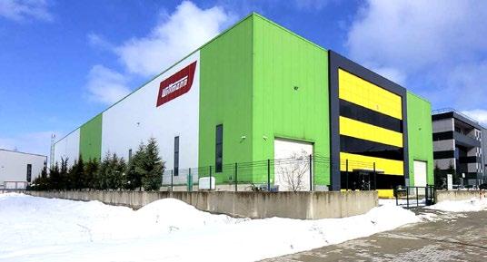
Production capacity was also increased with the addition of a new facility in Dilovası, Turkey. The main focus of this plant’s operations will lie in sheet metal and metal processing, and will also include complete products for the Wittmann Group’s range of auxiliaries. Production began in January this year, and will support the operations of the company’s production plants in Austria and France.
sector with great potential for Tekna. We believe that this order is proof of the quality of our products and the strength of our brand,” stated Luc Dionne, CEO of Tekna.
Tekna’s titanium alloy powder is said to offer a high level of sphericity, low oxygen content, high density (bulk and tapped) as well as controlled grain size. In addition to Ti64 titanium alloy powder, Tekna produces tungsten and tantalum powders for MIM applications.
www.tekna.com
Additions to the main building of Wittmann USA Inc in Torrington, Connecticut, USA, expected to be completed within the next two months, will provide additional space for automation solutions and complete injection moulding cells in future. Another project underway is the building of the Hungarian sales and service organisation Wittmann Robottechnikai Kft. in Törökbálint, near Budapest. Its completion is planned for mid-2023.
Reporting on its financial results for 2022, the group stated a sales figure of €376 million. This was said to be roughly on par with the previous year and was characterised by a high order intake during the first half of the year. However, issues regarding the supply of purchased parts – in particular, electronic components – prevented the realisation of these sales.
For the current fiscal year, Michael Wittmann, president of the Wittmann Group, stated that he expects an increase in sales of approximately 10%. This estimate was said to be based on the company starting 2023 with a high order backlog, and a market beginning to show signs of improvement in the supply situation.
Wittman concluded, “With our energy-efficient and powerful machines and products, we are in a strong position and can look into the future with optimism.”
www.wittmann-group.com
16 PIM INTERNATIONAL SUMMER 2023 © 2023 INOVAR COMMUNICATIONS LTD VOL. 17 NO. 2 | contents | news | events | advertisers | website | newsletter | Industry news
Wittmann Group’s new facility in Dilovası, Turkey (Courtesy the Wittmann Group)
We ensure 100% batch-to-batch consistency, a wide range of alloys, and 36 years of supplying MIM feedstocks for mission-critical parts.


www.ampmim.com
Scan the QR code or click here to view our current list of alloys www.ampmim.com/resources Advanced Metalworking Practices (AMP) manufactures and supplies a wide range of both standard and custom-configured MIM feedstocks for your application. Contact Chris Chapman at cchapman@ampmim.com or 724-396-3663.
US
Regardless of the complexity of your custom application and formulation, it remains standard for us with our quality systems, technical support, and two proprietary binding systems.
CUSTOM FORMULATIONS ARE STANDARD FOR
Ecrimesa digitises MIM workflow to improve efficiency and productivity


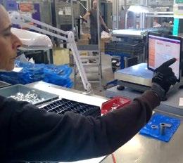
Ecrimesa Group, based in Santander, Spain, has undergone a digitisation of its guidelines/process sheets in an effort to improve its efficiency and productivity. This is a project developed internally and led by Daniel Seco, MIM Process Engineer, and Julio López, Head of Industry 4.0. The development phase spanned six months; the company is now in the implementation phase.
In industrial environments, the applicable work standard – ISO/UNE, etc. – indicates that the operator must have a guideline for the process to be carried out. This guideline, also called a process sheet or work standard, is a detailed document which describes the specific steps and tasks required to perform that process. At Ecrimesa, operators would need to print out the most
recently-updated version of these sheets and take it to their post as they worked. As each process worked might necessitate several of these work guides, Ecrimesa’s Metal Injection Moulding plant works with over 2,000 references.
To undertake this project, engineers made use of the Microsoft Dataverse (which includes Microsoft Teams, Dynamics 365 and SharePoint). Process engineers create, update, and modify the work guidelines. The operators, from the tablet that they have at their workstation, type the reference number of the part. The application tells them which patterns are active and they select the one corresponding to the task to perform. Currently, the company has six of these tablets in place, but intends to expand this to all positions.
An app is used to identify which guidelines are active, allowing the operator to select the one corresponding to the task (Courtesy Ecrimesa)
To date, the project has enabled a reduction in paper, thus reducing cost and materials waste; a reduction in mistakes by ensuring operators have the most recent guidelines; and improved efficiency, as operators aren’t required to source the guidelines from outside their workstations.
www.ecrimesagroup.com

18 PIM INTERNATIONAL SUMMER 2023 © 2023 INOVAR COMMUNICATIONS LTD VOL. 17 NO. 2 | contents | news | events | advertisers | website | newsletter | Industry news FINAL_AMT_AD_W175xH120mm_210222.indd 1 22/2/22 5:49 PM
Arburg celebrates successful Anniversary Days 2023
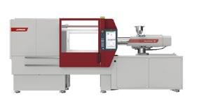
Arburg Anniversary Days, held from March 8-11 in Lossburg, Germany, welcomed 5,700 customers from fifty-three nations. The event –traditionally called Technology Days – spanned the company, with more than fifty exhibits focusing on sustainability, digitalisation, energy efficiency and automation.
On display in Arburg’s Customer Centre was the new hybrid Allrounder 470 H, whilst components made via Injection Moulding and Additive Manufacturing were displayed throughout the event.
With a focus on energy efficiency, the company also highlighted its new ‘Action Plan: Energy’, which includes advice on measures to help customers significantly reduce costs in Injection Moulding production and optimise energy requirements throughout the entire production process, beyond the machine itself (see page 91).
How existing machines can be energy-optimised through retrofits – for example, with fully insulated cylinders, Arburg energy saving systems AES and IE3 class motors – was demonstrated in a practical manner in the service area. There, visitors were also able to find out how to quickly get a new warehouse machine via the customer portal app Ready2Go. Arburg can also provide documented consumption measurements for businesses that require detailed energy data for certification.
The Efficiency Arena hosted a total of nine stations, six on the topic of arburgGREENworld and three on arburgXworld. Arburg and selected partners along the entire value chain demonstrated how digitalisation and innovative solutions enable a sustainable circular economy.
Selected partners provided information on current topics such as marking, identifying, sorting and recycling, supported by the transmission of data along the value chain. Arburg also presented its sustainability strategies, the arburgXworld customer
portal and the ALS host computer system in the Efficiency Arena.
As this year marked the 100 th anniversary of the company’s founding, there was also a special event available to visitors: the Arburg Cube. This offered a multimedia tour through the company’s history.
The event also marked its 100,000 th visitor on March 8, which takes into account each attendee
Arburg welcomed the 100,000 th visitor to its Technology Days event (Courtesy Arburg)
since the introduction of Technology Days in 1999.
www.arburg.com
MIM debind and sinter vacuum furnaces
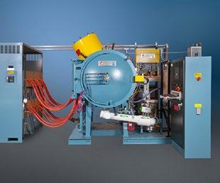
Over 6,500 production and laboratory furnaces manufactured since 1954

• Metal or graphite hot zones
• Processes all binders and feedstocks
• Sizes from 8.5 to 340 liters (0.3–12 cu ft.)
• Pressures from 10-6 torr to 750 torr
• Vacuum, Ar, N2 and H2
• Max possible temperature 3,500°C (6,332°F)
• Worldwide field service, rebuilds and parts for all makes
19 SUMMER 2023 PIM INTERNATIONAL VOL. 17 NO. 2 © 2023 INOVAR COMMUNICATIONS LTD | contents | news | events | advertisers | website | newsletter | GETPDF Industry news
Centorr Vacuum Industries 55 Northeastern Blvd Nashua, NH 03062 USA Tel: +1 603 595 7233 Fax: +1 603 595 9220 Email: sales@centorr.com
TM Injectavac®
www.centorr.com MIM-Vac
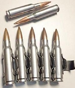
CTC receives patents for MIM ammunition cartridge cases
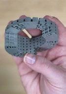
Concurrent Technologies Corporation (CTC), Johnstown, Pennsylvannia, USA, has been awarded two patents for a new shell case design produced by Metal Injection Moulding. The patents detail the invention of a single-piece, high-strength metallic cartridge case that is said to be stronger, stiffer and lighter than traditional brass.
The new design is a joint development between CTC and the US Army to improve a soldier’s effec -
tiveness through increased lethality, improved accuracy, and reduced ammunition weight.
Several cartridge calibres have been demonstrated with distinct advantages over competing solutions, such as hybrid metallicpolymer and multi-piece metallic cartridge cases. Metal injection moulded cartridge benefits reportedly include:
• 30% case weight reduction vs. brass
• High-pressure capability, up to 100 ksi tested
• Increased muzzle velocity, up to 10% over brass
• Increased accuracy (sub-MOA [Minute of Angle])
• Durable stainless steel case material with reliable functionality from -54°C to 107°C
• Rugged, single-piece design with no corrosion issues
through private commercialisation.
“This award comes at a time when global commodity prices for copper and brass are at all-time highs. The use of high-strength, lightweight stainless steel cartridge cases in ammunition production reduces manufacturing costs,” stated Edward J Sheehan, Jr, CTC president and CEO. “The CTC team has done an outstanding job of analysing requirements, developing a solution, and ensuring it is cost effective and scalable.”
Additional cost savings include:
• Reduced fuel and transportation costs from cartridge weight savings
• Easy firing range cleanup due to cases being magnetic
• Reloadable for consumer and competitive shooting
CTC has earned a patent for a MIM ammunition cartridge case that offers many benefits to the US military and commercial manufacturers
(Courtesy CTC)
• Compatible with existing brass case taper, trim, load, assemble, and pack manufacturing infrastructure United States Patents 11465207 and 11493314 are intended to protect the US government’s ability to organically produce and supply this technology to the warfighter, but allow cost reduction and maturation
Sandvik’s metal powder shop Osprey Online is open for business
Sandvik AB, Sweden, reports that Osprey® Online, the company’s metal powder online store, has now officially opened. Osprey Online will initially offer titanium powders, maraging steel, and nickel-based superalloys, as well as stainless steels such as duplex and super duplex, austenitic, martensitic, and precipitation hardening steels from stock through an on-demand platform accessible from any device.
The webshop offers a range of standardised alloy powders for Additive Manufacturing and will service Europe as a first step, with additional markets being included shortly.
The platform was launched with a special episode of the company’s interactive webinar series Additive
By Sandvik: Material Matters, and offered viewers insights into its range of alloys.
“We’re extremely excited to get this advanced technology to the warfighter to reduce their combat load and increase their mobility and lethality,” added Shawn Rhodes, CTC Principal Mechanical Engineer. “It’s an honour to develop technologies that benefit those who protect our country.”
The activity that led to this patent is part of CTC’s overall ammunition and weapon systems engineering services. The shell casing design inventors are Todd Skowron, Juan Valencia, Shawn Rhodes, and William Brueggen.
www.ctc.com
Luke Harris, Sales Director at Sandvik Additive Manufacturing, stated: “It was such a great honour to take part in this webinar, and to finally unveil Osprey Online in full. Getting to interact with the audience while presenting this solution and the ways in which it can make a true difference in our customers’ businesses, was so rewarding. Now we’re eagerly anticipating feedback, to keep improving and remain the most customer-centric partner we can be.”
www.metalpowder.sandvik/en/ webshop
www.metalpowder.sandvik
20 PIM INTERNATIONAL SUMMER 2023 © 2023 INOVAR COMMUNICATIONS LTD VOL. 17 NO. 2 | contents | news | events | advertisers | website | newsletter | Industry news
OSPREY® ONLINE THE METAL POWDER WEBSHOP

Imagine being able to order Osprey® metal powders at any time, from any device. Imagine hassle free ordering, fast shipping, and premium quality straight from the source. Osprey® Online is open for business – stocked with powders and expertise! Browse our online alloy selection optimized for additive manufacturing, including titanium, maraging steel, nickel-based superalloys, and stainless steels. Just add to cart, and we'll ship within 48 hours!
S HOP NOW M E TA L PO WDER.SANDVIK/OSPREYONLINE


www.polymim.com Subsidiary of the Polymer -Group Luxury Goods Aerospace Automotive Medicine Consumer Goods Mechanical Supplier
Feedstocks PolyMIM® Water soluble binder system PolyPOM Catalytic binder system GranuP 3D-Printing Materials rint PolyMIM GmbH is a manufacturer that offers two different binder systems for Metal injection Moulding High performance as well for the 3D -Printing process based on the water soluble binder system These two binder systems have excellent characteristics during the production process and combine attractive prices with worldwide availability
for MIM/PIM
China’s Avimetal AM offers over two hundred metal powders
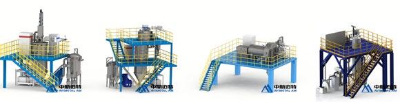
Avimetal AM, a subsidiary of Jingcheng Electromechanical, Beijing, China, entered the metal Additive Manufacturing equipment market in 2021, adding four new Laser Beam Powder Bed Fusion (PBF-LB) AM machines to its portfolio in 2022. In addition to machine development, the company also produces a wide range of metal powders tailored to Additive Manufacturing and other metal powder-based technologies, including Metal Injection Moulding, Hot Isostatic Pressing (HIP) and Powder Metallurgy (PM).
Established in 2015, the stateowned company now has three facilities in China, two of which are dedicated to metal powder production and one for building its metal AM machines. Its powder production equipment includes Vacuum Induction Melting and Inert Gas Atomisation (VIGA), Electrode Induction Melting Inert Gas Atomisation (EIGA), Plasma Rotating Electrode Process (PREP) and Plasma Atomisation (PA).
In total, Avimetal offers more than 200 metal powder alloys, and has a current annual capacity of over 5,000 tons. The range includes titanium alloy powders such as CpTi, Ti6Al4V, Ti6Al4VELI, Ti-6.5Al-1Mo-1V-2Zr, Ti-6Al-2Sn-4Zr2Mo-0.08Si, TiAl4822; superalloy powders including In718, In625, Hastelloy X, M247, Haynes188, NiTi50; aluminium alloy powders such as AISi7Mg, AISi10Mg; refractory metal powders including Ta, W, Mo; cobalt-chromium powders such as CoCrW, CoCrMo, CoCrMoW as well as steel powders including 18Ni300, 316L, 17-4PH. Customised
HP enhances its Binder Jetting offer, adds Endeavor 3D as Metal Jet manufacturing partner
HP Inc, Palo Alto, California, USA, has announced a raft of solutions to help customers simplify workflows and reduce costs as they move to highvolume Additive Manufacturing part production. At this year’s Rapid+TCT event in Chicago, USA, May 2-4, the company announced enhancements to its software, service and materials offerings, as well as offering new automation solutions.
“Companies large and small, in markets around the world, are turning to 3D printing for faster, more flexible, more personalised, and more resilient and sustainable production,” said Didier Deltort, president of Personalisation & 3D Printing, HP Inc.
“It’s promising to see the development of so many game-changing
3D printed applications across automotive, consumer, healthcare, and industrial, but to disrupt industries, these parts must be manufactured at scale. To help our customers scale effectively and efficiently, HP remains laser-focused on delivering industrial hardware, supplies, software, and services supporting the entirety of the digital production workflow from application design to final parts production.”
HP also announced it was promoting several of its current Digital Manufacturing Network (DMN) members to its exclusive group of HP Digital Manufacturing Partners (DMP) to meet the growing demand for final parts production. More than sixty members around the world are now
grades of metal powders are also available.
Over the years, Avimetal has provided metal AM machines, metal powders, and process technology services to more than 5,000 customers worldwide. The company’s largest PBF-LB machine now boasts a build volume of 1250 x 1250 x 1500 mm, with a maximum number of twelve lasers, significantly improving the capacity and production efficiency of large and complex structural components.
As well as equipment an metal powders, Avimetal also offers technical training, component design optimisation, modelling, heat treatment and surface treatment solutions.
en.avimetal.com
providing manufacturing services and enabling OEMs to build their digital supply chain.
The recently-promoted members include Athena, Endeavor 3D and The Technology House (TTH). It was announced that Endeavor 3D is expanding its HP-enabled manufacturing services in its factory in Douglasville, Georgia, adding HP’s Metal Jet S100 solution to its existing fleet of HP Jet Fusion 5200 and 5420W systems.
“Adding HP’s Metal Jet capabilities to our manufacturing services enables us to provide more to our customers,” stated Phil Arnold, CEO, Endeavor 3D. “Top-down, our expert engineering team believes that this technology will help manufacturers reshore production and we are excited to be a major player in that supply chain.”
www.hp.com
www.endeavor3d.com
23 SUMMER 2023 PIM INTERNATIONAL VOL. 17 NO. 2 © 2023 INOVAR COMMUNICATIONS LTD | contents | news | events | advertisers | website | newsletter | GETPDF Industry news
Avimetal’s powder production equipment includes VIGA, EIGA, PREP and PA options (Courtesy Avimetal)
Novel hybrid Additive Manufacturing process for complex ceramics
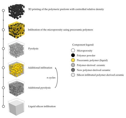
In a recent PhD project at the SUPSI University in Switzerland, material engineer Marco Pelanconi developed a novel hybrid Additive Manufacturing process to fabricate complex ceramic structures. The approach involves the Additive Manufacturing of polymeric preforms with high microporo -
sity through Laser Beam Powder Bed Fusion (PBF-LB), combined with infiltration with preceramic polymers.
Following the Additive Manufacturing stage, pyrolysis is used to obtain a polymer-toceramic conversion at around 1000°C. A final densification is performed via molten silicon infil -
tration to achieve ceramic parts with high density.
Pelanconi used the Sintratec Kit, an open parameter polymer PBF-LB machine from Sintratec, Switzerland. “The Kit allowed us to change a lot of printing parameters, including powder surface temperature, layer thickness, laser speed, hatching spacing, and more, making it easy to control the porosity of the 3D printed parts,” stated Pelanconi.
Varying these factors enabled Pelanconi to achieve an ideal porosity and part quality, said to be crucial for further infiltration.
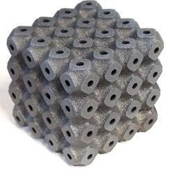
With Pelanconi’s process, complex shapes of various ceramics (SiC, SiOC, SiCN, SiSiC etc.) can be produced relatively fast and efficiently (Courtesy Hybrid Materials Laboratory SUPSI)
To illustrate how this method could be used for especially complex shapes, Pelanconi’s research focused on two cylindrical porous structures with different topologies: a rotated cube and a gyroid. After Additive Manufacturing with Sintratec PA12 and subsequent conversion into a ceramic, the resulting parts reportedly exhibited outstanding mechanical and thermal properties. They maintained their shape without distortion or macrocracks, despite a shrinkage of ~25%. According to Pelanconi, their impressive biaxial strength of 165 MPa could still be increased through further process optimisation.
Ceramics are well-suited to use in extreme environments, such as heat exchangers, catalyst supports, thermal storage, burners or aerospace. The use of Additive Manufacturing to produce complex ceramic architectures is a promising development. “These classes of materials offer unmatched thermo-mechanical properties that cannot be provided by steels, such as high temperature resistance, high oxidation resistance, high thermal shock resistance and high strength,” added Pelanconi.
The hybrid Additive Manufacturing process steps (Courtesy Hybrid Materials Laboratory SUPSI)
It was stated that the innovative approach could be exploited by high-tech industries thanks to the many different ceramic materials obtainable from a wide range of preceramic polymers.
www.supsi.ch
24 PIM INTERNATIONAL SUMMER 2023 © 2023 INOVAR COMMUNICATIONS LTD VOL. 17 NO. 2 | contents | news | events | advertisers | website | newsletter | Industry news
For improved sustainability, variety and performance, choose forAM®
In the world of metal powders, Höganäs is always at the forefront of innovation. From more sustainable production processes to new and patented powder compositions, we are dedicated to offering you the optimal solutions while reducing environmental impact. With forAM ®, our range of metal powders designed for additive manufacturing, we can offer powders designed for any application.
The forAM ® range includes nickel, iron, cobalt, copper, titanium and aluminium powders in a variety of grades and compositions. Combining optimal powder performance with improved sustainability is a priority for Höganäs. In addition to our material innovations, we have also committed to Science Based Targets and are founding members of the Additive Manufacturing Green Trade Association, demonstrating our ongoing committing to leading sustainable transformation in our industry.

— 3203HOG www.hoganas.com
Lithoz and SiNAPTIC partner with the purchase of seven CeraFab S65 machines
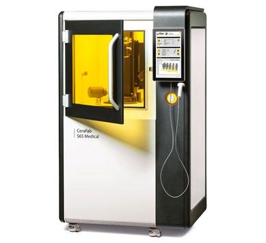
Lithoz, Vienna, Austria, and SiNAPTIC, Lafayette, Colorado, USA, announced a major strategic partnership agreement, including sales and marketing activities, at Rapid + TCT 2023, May 2-4 in Chicago, Illinois. The deal included the purchase of seven Lithoz CeraFab S65 Additive Manufacturing machines for SiNAPTIC’s new research centre in Lafayette.
Besides the development of their medical device products and R&D activities, SiNAPTIC will offer their expertise for OEM contract manufacturing on the rapidly-accelerating North American market, responding to the numerous enquiries of OEMs from various industries. They will also distribute Lithoz AM machines, materials and software across North America.
A new ‘SiNAPTIC powered by Lithoz’ branding will also be placed by SiNAPTIC on their products. The agreement between Lithoz and SiNAPTIC is intended to ultimately bring new Additive Manufacturing solutions to a wider audience in the US, Canada, and Mexico. With more businesses now being able to take advantage of the capabilities offered by technical ceramics, it is expected to give businesses a new way to bring
many types of new products to market faster and with less risk.
“By partnering with Lithoz, the experienced global leader in ceramic 3D printing, SiNAPTIC will gain access to a comprehensive range of technical ceramics, technologies, and unparalleled expertise,” stated Bryan Scheer, SiNAPTIC’s CEO. “This partnership will allow SiNAPTIC to focus on optimising efficiency in manufacturing and scaling production for our customers.”
SiNAPTIC is comprised of two business divisions –SiNAPTIC Technologies and SiNAPTIC Surgical, each with a different focus. SiNAPTIC Technologies provides R&D and prototyping all the way to scaled OEM manufacturing, whereas SiNAPTIC Surgical is currently undergoing FDA approval to become a fully-integrated original medical device producer.
At the Lithoz booth at Rapid, SiNAPTIC showed one of their CeraFab S65 medical Additive Manufacturing machines live at the event, which also marked the first live appearance of the S65 AM machine at a tradeshow, alongside examples of parts additively manufactured by the machine.
Dr Johannes Homa, CEO, Lithoz, added, “With SiNAPTIC we have found the right partner for the rapidly-growing volume of enquiries on the North American market at exactly the right time! With the strong passion and huge momentum they bring on their mission to disrupt the medical device market with unique 3D printed technical ceramics, we quickly came to the conclusion that they are also the right company to be a leading contract manufacturer for the many different enquiries, from prototyping to serial production we have received from OEMs of various verticals during the last months.”
www.lithoz.com
www.sinaptictech.com

26 PIM INTERNATIONAL SUMMER 2023 © 2023 INOVAR COMMUNICATIONS LTD VOL. 17 NO. 2 | contents | news | events | advertisers | website | newsletter | Industry news
The deal includes the purchase of seven CeraFab S65 Additive Manufacturing machines for SiNAPTIC’s new research centre in Lafayette (Courtesy Lithoz)
FreeFORM expands offering with Tritone’s MoldJet technology


Tritone Technologies, Rosh Ha’ayin, Israel, has announced that FreeFORM Technologies, St Marys, Pennsylvania, USA, will expand its service offerings by adding a Tritone Dominant sinter-based Additive Manufacturing machine. With Tritone’s Dominant and MoldJet powder-free technology, FreeFORM intends to broaden the range of materials and geometries it can provide to its diverse customer base.
Through this partnership, Tritone plans to strengthen its presence in North America following the recent opening of a US-based subsidiary. FreeFORM has a strong leadership team with experience in Metal Injection Moulding, Powder Metallurgy, applications and automation.
“We have followed Tritone with great interest since we first saw their technology at Formnext 2019,” stated Nate Higgins, president, FreeFORM. “Their approach is unique and addresses some points that we think are important to expand portfolio reach. At FreeFORM our aim is to solve problems. Part of it is to have great partnerships. We look forward to working with Tritone and using their unique technology with our customers.”
The Dominant system is based on Tritone’s MoldJet technology, a sinter-based Additive Manufacturing solution which enables industrial production of high-quality metal and ceramic parts at an industrial speed. Built for producing large quantity of high-density parts with complex geometries and a wide variety of materials, the technology enables parallel manufacturing of parts of various sizes, shapes, and applications. MoldJet technology also enables the quick switchover between metal and ceramic materials.

“FreeFORM is a true pioneer in the sinter-based Additive Manufacturing community and we are thrilled to welcome them to the growing Tritone North America family of service
providers,” added Ben Arnold, VP Business Development, NA, Tritone Technologies. “Our strategy is to grow our presence in the region by making sure all prospects have easy access to our technology on a service basis and this is an important step in that direction.”
www.tritoneAM.com
www.freeformtech.com

27 SUMMER 2023 PIM INTERNATIONAL VOL. 17 NO. 2 © 2023 INOVAR COMMUNICATIONS LTD | contents | news | events | advertisers | website | newsletter | GETPDF Industry news
FreeFORM Technologies parts produced using Tritone’s Dominant system (Courtesy FreeFORM Technologies)
Your One-Stop-Shop
MIM2023 shines light on injection moulding of metals, ceramics & carbides


MIM2023, the International Conference on Injection Moulding of Metals, Ceramics and Carbides took place in Costa Mesa, California, USA, February 27-March 1. Organised by the Metal Powder Industries Federation (MPIF), the hybrid conference welcomed over 135 delegates, representing over seventy-five companies from thirteen countries.
The event opened with a keynote presentation on Industry 4.2 by Dr Diran Apelian, University of California, Irvine. The author described what he believed smart factories would look like and how connected supply chains will work, including the need for sustainable materials, advanced manufacturing, and how corporations will need to pivot from focusing on
capital and capitalism, to investment in procuring and retaining talent.
The keynote was followed by twenty-seven technical presentations. Additionally, twenty companies showcased their products and services during a tabletop exhibit, with many of the exhibitors showcasing the latest developments during the Technological Process & Product Innovations presentations (Our full conference report is published on page 91).
The Metal Injection Molding Association (MIMA) also provided six students with grants to attend the conference. Not only were the grant recipients given the opportunity to gain exposure to the MIM industry, but each provided a presentation on work at their universities.
www.mpif.org
Markforged posts record Q1 results

Markforged has shared its financial report for the first quarter 2023. As of March 31, the company showed a revenue increase of 10% to $24.1 million, up from $21.9 million in the first quarter of 2022.
Shai Terem, President and CEO of Markforged, stated, “We have started the year strong with another record first quarter revenues and the largest pipeline in our company’s history. Demand for the Digital Forge grew across all geographies in Q1, as an increasing number of manufacturers are choosing our metal and composite solutions to solve mission-critical metal applications at the point of need.”
Gross profit was $11.6 million in the first quarter, with non-GAAP gross profit of $11.9 million. However, a net loss of $19.0 million in Q1 2023 and a non-GAAP net loss of $13.3 million, was reported.
“We believe our Q1 results are a reflection of strong execution of our strategy and an early indicator of the meaningful opportunity for Markforged in the coming quarters as we remain laser-focused on margin expansion and driving profitable growth,” Terem concluded.
www.markforged.com
28 PIM INTERNATIONAL SUMMER 2023 © 2023 INOVAR COMMUNICATIONS LTD VOL. 17 NO. 2 | contents | news | events | advertisers | website | newsletter | Industry news
Unique inert gas atomizing technology produces highly specified, spherical metal powders for MIM and AM applications. Team with history of developing and producing fine gas atomized powders since 1990.

Specializing in sub 30 micron powders, Ultra Fine has the technical capability to work with you to develop and produce the powder to suit your application. Ultra Fine offers flexibility and quick turn-around times.
With partner Novamet Specialty Products Corp., Ultra Fine provides various after treatments, coatings and other capabilities using Ultra Fine’s high quality powders.

500 Park East Drive | Woonsocket, RI 02895 USA 1420 Toshiba Drive, Suite E Lebanon, TN 37087 USA www.novametcorp.com MIM & BINDER-JET AM METAL AS9100:2016 CERTIFIED
POWDERS
Providing Quality Metal Powders Since 1976 ww finepowder.com ISO9001:2015 CERTIFIED ISO9001:2015CERTIFIED
PM Tooling System
Demcon Metal Injection Moulding receives ISO 45001 certification
Demcon, Enschede, the Netherlands, has announced it is now ISO 45001 certified. This certification regards work safety and human well-being and has been implemented for all Demcon companies as the certificate has been issued across Demcon Holding, Demcon Advanced Mechatronics, Demcon Metal Injection Moulding and Demcon Production.
Bianca Screever, Director of Operations at Demcon shared, “We are proud that we have obtained the ISO 45001 certificate. This shows that we take occupational safety and health seriously.”
Demcon MIM specialises in the use of stainless steels such as 316L and 17-4PH. By mixing its own feedstock, the company states it can process most other metals available in powder form, and lists low-alloy steels, nickel-balanced materials and others.
The certification follows Demcon’s ISO 9001 and ISO 13485 qualifications.
www.mim.demcon.com
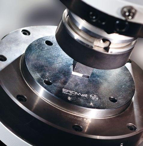
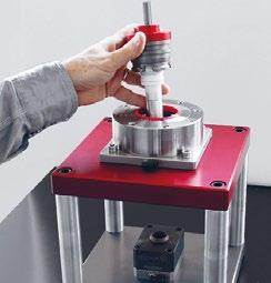
www.erowa.com
Pfeiffer offers new vacuum calculator

Pfeiffer Vacuum, Asslar, Germany, has introduced a vacuum calculation tool to identify specific vacuum products for users’ applications, examine evacuation, as well as pump down curves and perform different calculations for self-configurated pumping solutions. The tool also enables customers to compare different vacuum solutions with each other.
“With our new vacuum calculator, we aim to make the lives of our customers easier,” stated Daniela Kunzig, Head of Digital Business. “When looking for the right vacuum solution, the technical parameters can be inserted into the tool and the matching products are displayed. Moreover, customers can perform different calculations for existing pump solutions.”
The vacuum calculator is available via the Select & Request web portal. A contact form is linked to each search or calculation via which the customers can directly contact the sales engineer in charge to request a quote.
www.pfeiffer-vacuum.com
30 PIM INTERNATIONAL SUMMER 2023 © 2023 INOVAR COMMUNICATIONS LTD VOL. 17 NO. 2 | contents | news | events | advertisers | website | newsletter | Industry news
The EROWA PM Tooling System is the standard interface of the press tools between the toolshop and the powder press machine. Its unrivalled resetting time also enables you to produce small series profitably.
more info
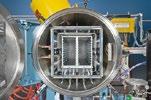
Plansee’s newest hot zones reduce energy consumption in hightemperature processes
Plansee High Performance Materials, a Plansee Group company, headquartered in Reutte, Austria, has announced its latest generation of hot zones for industrial furnaces. All versions of these new models are said to save a significant amount of energy, even at maximum performance, thus lowering both the customers’ operating costs and CO 2 footprint.
The industry faces the challenge of saving energy on a large scale, explains Plansee, but this efficiency can’t be at the expense of quality. The demand for high-performance, sustainable solutions becomes a complex task, however, when industrial processes require particularly large amounts of energy. This is the case for high-temperature vacuum furnaces used for heat treatment in sectors such as aviation or medical technology, where working temperatures of 1,000-1,800°C are reached.
Plansee supplies manufacturers of industrial furnaces with metallic hot zones made from molybdenum, molybdenum alloys, and tungsten, which are used in high-temperature processes and ensure that the temperature in the furnace is optimally distributed. The energy balance of these processes depends on the quality of the hot zones and if they are not optimised for the respective area of application, an unnecessary amount of heat (and, thus, energy) is lost.
Plansee’s new hot zone models reportedly save up to 27% of energy compared to the previous iterations, and the lightweight design of the support frame means that the new models weigh up to 15% less.

The constructions and materials used in the heating system are said to ensure that the batch is heated optimally, and issues such as short circuits or sagging of the heating element are almost impossible. Further, the heated parts of the furnace can be efficiently cooled
using gas, with nozzles placed in optimal positions determined by simulations.
Another addition is the ‘FlowBox,’ which enables the smooth outflow of gas at the rear of the hot zone. Together, the nozzle and FlowBox work to ensure that the batch is cooled precisely, without the unintentional formation of further cooled
areas in the furnace. Another feature highlighted by Plansee is the smart mounting of the front door which adapts to the temperature changes inside the hot zone and therefore prevents heat from being lost.
Plansee’s hot zones can be configured in advance for individual requirements via an online tool. If special individual parts made from molybdenum or tungsten are required to meet specific needs, Plansee can produce these independently via Additive Manufacturing.
www.plansee.com
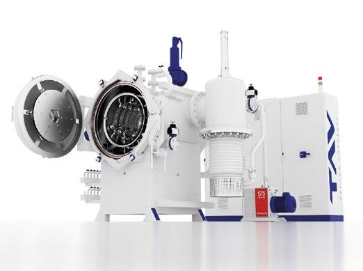
31 SUMMER 2023 PIM INTERNATIONAL VOL. 17 NO. 2 © 2023 INOVAR COMMUNICATIONS LTD | contents | news | events | advertisers | website | newsletter | GETPDF Industry news THE PERFECT HEAT TREATMENT SOLUTION FOR THE PIM INDUSTRY
range of standard and customized VACUUM FURNACES for INDUSTRY and R&D LABORATORIES.
vacuum
HIGH TEMPERATURE VACUUM SINTERING
DEBINDING & SINTERING
DEBINDING/PRE-SINTERING
HIGH PRESSURE SINTER-HIP
MIM, CIM, HARD METAL TAV VACUUM FURNACES SPA Via dell’Industria, 11 - 24043 Caravaggio (BG) - ITALY ph. +39 0363 355711 - info@tav-vacuumfurnaces.com www.tav-vacuumfurnaces.com
Wide
Our
furnaces solutions: -
-
-
-
Vacuum thermal technologies:
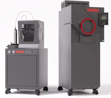
Rapidia lowers cost of metal AM machine and furnace package
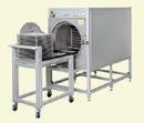
Rapidia Inc., headquartered in Vancouver, British Columbia, Canada, has announced a significant reduction in the price of its metal Additive Manufacturing hardware, in an effort to make the technology more accessible. The company’s Conflux 1 system – consisting of a metal AM machine and vacuum sintering furnace – is now available starting from $99,000.
In 2020, Rapidia entered a partnership with ExOne, where ExOne marketed the platform as the ExOne Metal Designlab AM machine and X1F sintering furnace. This was a mutually-beneficial arrangement, explained Rapidia, as it allowed access to ExOne’s established brand and distribution network, whilst expanding ExOne’s portfolio. When ExOne was acquired by Desktop Metal
in late 2021, however, the partnership ended.
Since then, Rapidia has spent the past year building a sales team and network of their own. By controlling the entire customer journey, Rapidia states it is now able to deliver the Conflux 1 platform at a more accessible price.
Rapidia’s two-step AM technology, developed over several years and first revealed in 2019, works by extruding a flowable bound metal paste. The paste is dried, layer by layer, creating green parts with 90% less binder than found in metal filaments or Metal Injection Moulding feedstocks. As a room-temperature process, the technology is not limited by the speed of melting and then cooling polymer carriers. Moreover, the low binder content allows
green parts to be put directly into short sintering cycles, skipping the debinding step and ultimately outputting many finished parts in under twenty-four hours.
“Our metal printing technology is accessible because of its ease of use and low operating cost,” stated Artem Bylinskii, CEO. “We’re now in a position where we feel we can be more proactive and more disruptive by making our technology more accessible in price too.”
Bylinskii added, “We see a gap in metal Additive Manufacturing because the cost of entry for production solutions is so high. It’s a major risk for companies to borrow upwards of half a million to get that capability. With our new pricing, we hope to provide a more scalable production solution where businesses can start with a couple of machines, and then continue adding printers to their fleet at an easily digestible cost.”
www.rapidia.com
3D Lab granted patent for ATO ultrasonic metal atomisation technology
3D Lab sp. z.o.o., based in Warsaw, Poland, has announced that its ATO metal atomisation method has been granted a patent. The company’s ATO atomiser creates spherical metal powders using an ultrasonic vibration technique, rather than the morecommon gas or water atomisation methods.
The ATO device includes infusible sonotrode with a melting tip, mate -
rial melting system, input material delivery system, process chamber and piezoelectric transducer. It is designed to ensure the input material is heated to its melting point, atomised, and converted into spherical powder particles. Moreover, it includes a mechanism for controlling the atomisation process and for collecting the spherical powder particles.
“We want to take a moment to recognise and thank everyone involved in this achievement. It is through your dedication, hard work, and perseverance that we have been able to bring this innovation to life,” the company stated.
Due to the development of ATO, 3D Lab has been able to expands its activities in the area of novel metal powder technologies, and the patent will allow the company to successfully defend the invention in regional markets.
www.metalatomizer.com
32 PIM INTERNATIONAL SUMMER 2023 © 2023 INOVAR COMMUNICATIONS LTD VOL. 17 NO. 2 | contents | news | events | advertisers | website | newsletter | Industry news
The Rapidia system builds parts using water-based metal paste technology (Courtesy Rapidia)
Rapidia’s Conflux 1 system includes a vacuum furnace (Courtesy Rapidia)
Aidro achieves DNV certification for AM with both PBF-LB and BJT
Aidro srl, a subsidiary of Desktop Metal, based in Taino, Italy, has received what it has reported to be the first-ever global AM manufacturer certification from DNV, a risk management and quality assurance society for the oil & gas and maritime industries, for two metal Additive Manufacturing technologies. DNV awarded DNV-SE0568 and DNV-ST-B203 to Aidro’s Taino facility.
The certifications follow a rigorous review process by DNV, including an audit of Aidro’s facility, metal AM processes qualification, as well as qualification of parts produced by Aidro through Additive Manufacturing methods, including mechanical, microstructural, and macrostructural tests. To achieve AMC 3 level certification for Laser Beam Powder Bed Fusion (PBFLB), DNV qualified a specific 316L part
produced by Aidro for a customer, as well as a 17-4PH part for Binder Jetting AMC 1 level certification.
“Our team is incredibly proud to receive this global certification for Binder Jetting and laser powder bed fusion,” stated Valeria Tirelli, president and CEO of Aidro. “The rigorous process used by DNV will enhance industry confidence in these Additive Manufacturing methods and continue to support the transition of the demanding energy, oil & gas, and maritime industries toward Additive Manufacturing 2.0. Customers taking the leap into the AM 2.0 future are already realising incredible benefits, including performance enhancements, lighter weight parts, distributed on-demand manufacturing and digital inventory that reduces the need for physical stock.”
“Aidro’s Binder Jetting certification showcases the great performance and reliability of the Shop System, and its ability to serve the most demanding industries such as the oil & gas industry,” added Desktop Metal Founder and CEO Ric Fulop. “We congratulate all of our Team DM employees at both Aidro and Desktop Metal who contributed to this achievement.”
DNV said Aidro’s qualification is an important step for the mission-critical industries to move into a new era of digital manufacturing.
Aidro has been working to drive the adoption of AM in the energy sector. Aidro’s work with DNV began in 2018, when it contributed to the drafting of the guidelines that became the basis of the DNV-ST-B203 standard. Aidro has also collaborated with the American Petroleum Institute and AM Energy to develop standards and promote the use of AM in the energy industry.
www.aidro.it
From Experts for Experts
34 PIM INTERNATIONAL SUMMER 2023 © 2023 INOVAR COMMUNICATIONS LTD VOL. 17 NO. 2 | contents | news | events | advertisers | website | newsletter | Industry news Heerstraßenbenden 10 D-53359 Rheinbach Germany + 49 - 2226 9087 - 0 + 49 - 2226 9087 - 10 sales@inmatec-gmbh.com www.inmatec-gmbh.com Technologies
INMAFEED INMAFLOW INMAPOM CIM-FEEDSTOCKS
GmbH
3 Binder-Strategy
Verder acquires Formulaction to expand particle characterisation portfolio
The Verder Group, headquartered in Haan, Germany, has announced the acquisition of Formulaction SA, based in Toulouse, France. As part of the group’s Scientific Division, Formulaction will be integrated into Microtrac MRB, a manufacturer of particle characterisation systems.

Formulaction develops laboratory equipment for analysing dispersion stability & shelf life, curing & drying processes and rheology. The addition of this company to the Microtrac MRB portfolio is expected to create a comprehensive suite of instrumentation for materials characterisation practitioners.
This merger adds Formulaction’s Turbiscan, Curinscan, Fluidcam and Rheolaser product lines to Microtrac’s own brand portfolio, including SYNC Laser Diffraction, Nanotrac Dynamic Light Scattering, Camsizer Dynamic Image Analysis and Belsorp Gas Adsorption Analysis.
“Since its creation, Formulaction has been at the forefront of technical innovation in helping scientists to directly assess key properties of their materials from early development to final product design or ‘End Use Properties’,” stated Gerard Meunier, CEO of Formulaction. “The integration of the Formulaction product portfolio into Microtrac MRB opens huge opportunities for the expanded group to provide added value to customers in their pursuit of innovative product development by delivering highquality solutions.”
Microtrac MRB’s and Formulaction’s combined technologies offer a comprehensive portfolio of solutions. The move will offer both companies access to new markets and opportunities, including:
• Particle Size and shape from 0.3 nm to 135 mm
• Surface and pore size distri -
bution using both physi- and chemisorption
• Catalyst analysis
• Porosity and density measurements
• Dispersion stability and zeta potential analysis
• Rheological properties
“We have been witnessing the development of Formulaction for years and are impressed with the technology and the agility of the team,” added Andries Verder, CEO, Verder. “The addition of the people and products from Formulaction is an important
building block in our drive to enable the progress for our customers in the world of particle characterisation.”
www.formulaction.com

www.microtrac.com
www.verder.com
35 SUMMER 2023 PIM INTERNATIONAL VOL. 17 NO. 2 © 2023 INOVAR COMMUNICATIONS LTD | contents | news | events | advertisers | website | newsletter | GETPDF Industry news PIMI Island Half Page Ad – Grow Profits – C Series.indd 1 12/7/22 2:15 PM
Gerard Meunier (left) and Andries Verder (Courtesy Verder Group)
Lithoz and Glassomer release additively manufactured quartz glass
Lithoz GmbH, headquartered in Vienna, Austria, has worked with Glassomer, a manufacturer of technical and optical components based in Freiburg, Germany, to develop a new type of glass capable of being additively manufactured. The new material, ‘LithaGlass powered by Glassomer’, is processed using Lithoz’s lithography-based ceramic Additive Manufacturing technology and results in components with high precision and mechanical stability.
As a slurry with a base of quartz glass, LithaGlass is reported to be closer to a ceramic than standard glasses, such as soda-lime glass. It offers the desirable material properties of high-performance fused silica glass, including a low thermal
expansion and high thermal shock resistance.
Glassomer classified Lithoz’s lithography-based technology as the only process capable of refining and additively manufacturing its material at such a high level.
“Glassomer’s choice of Lithoz’s LCM process as their key technology to achieve this innovation once again proves the sheer potential and flexibility of our system,” stated Dr Johannes Homa, CEO, Lithoz. “The new LithaGlass material brings our company one step closer to our vision – finding solutions to every challenge of today with a 3D-printed ceramic answer.”
Dr Frederik Kotz-Helmer, CSO of Glassomer explained, “Our trans -
enhances its sinter-based tooling solution with increased automation
Mantle, San Francisco, California, USA, has announced the release of its High-Precision Shaping package, which includes 0.006” and 0.010” ball mill cutting tools and automated toolpathing software. The package is intended to enable tool rooms to automate toolmaking process by producing sharp corners and edges without requiring EDM operations, thus reducing the time required to
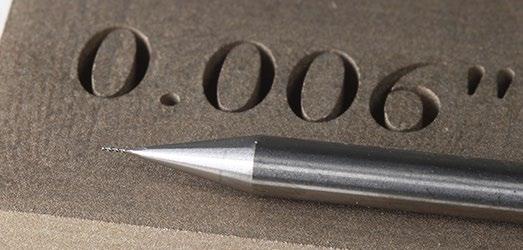
produce mould tools by up to 75%.
“At Mantle, our goal is to help tool rooms increase the number of complex mould tools they produce while reducing the time, cost, and labour to produce them,” stated Ted Sorom, co-founder and CEO, Mantle. “By deploying our new High-Precision Shaping capabilities, our customers can produce steel tools faster than ever –
parent high-purity glass solutions offer enormous potential for many applications, especially for highstability optical and technical parts. With Lithoz we have a powerful partner to make our glasses available for high precision 3D printing – which will significantly advance science and technology.”
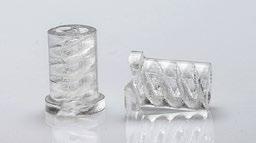
www.lithoz.com
www.glassomer.com
without requiring programming, setup, and operator time from overworked toolmakers.”
Mantle’s TrueShape technology combines Additive Manufacturing of its tool steel pastes with traditional CNC machining to refine the shape of AM tools and deliver accuracy as well as good surface finish and properties. Mantle’s new High-Precision Shaping package enables tool rooms to produce tools with radii under 0.003”, a 70% improvement compared to the .010” radii previously attainable, thereby eliminating more EDM operations.
“Mantle allows us to offer production-grade tooling to our customers in prototype time,” added Eric Derner, Technical Sales Applications Engineer at Nicolet Plastics, an injection moulder. “Mantle will allow us to reduce our need for offshore tooling, which introduces scheduling and supply chain risk, with comparable pricing. With Mantle’s H13 tool steel and new High-Precision Shaping capabilities, we can print tools in-house and deliver complex moulded parts to our customers weeks faster than before.”
www.mantle3d.com
36 PIM INTERNATIONAL SUMMER 2023 © 2023 INOVAR COMMUNICATIONS LTD VOL. 17 NO. 2 | contents | news | events | advertisers | website | newsletter | Industry news
Mantle
LithaGlass powered by Glassomer combines the properties of fused silica and soda-lime glass (Courtesy Lithoz)
The detail achievable using Mantle’s sinter-based metal Additive Manufacturing technology for tooling, with a 0.005” endmill for scale (Courtesy Mantle)
3D PRINTING IS YOUR SOLUTION
Material Options (Metal)
Material Options (Ceramics)
Build Envelope
Quantity
Tolerance capability
CONTACT FOR MORE DETAILS
17-4PH, SS 316, Tool Steel M2 & S-7, Inconel 625, 4140
Alumina 99.5%, Zirconia
~ 300 grams max, Footprint equivalent of baseball size or less, 0.02” (0.50 mm) wall thickness minimum
10~50 samples based on footprint. Larger quantities up to 1,000 pcs welcome depending on the part size.
Within 2% of the feature size, 2~3 Ra Surface finish, Option of finishing to closer tolerances available.
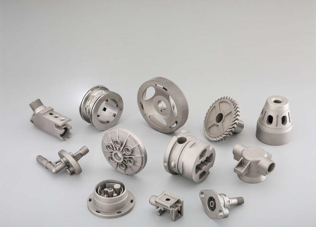
LOOKING FOR PROTO-SAMPLES IN 15 DAYS ? www.indo-mim.com ISO 9001:2015 / IATF 16949:2016 / AS 9100:Rev D / ISO 13485:2016 / ISO 14001:2015 NORTH AMERICA Email: Mukund.N@indo-mim.com Ph: +1 (210) 557-1594 EUROPE Email: InfoEU@indo-mim.com Ph: +49 1732656067 ASIA Email: InfoHQ@indo-mim.com Ph: +9198459 47783 / +91 98450 75320
Binder-Jetting Ceramic NPJ Metal/Ceramic SLA
LPBF
PVA TePla expands production capacities as demand grows
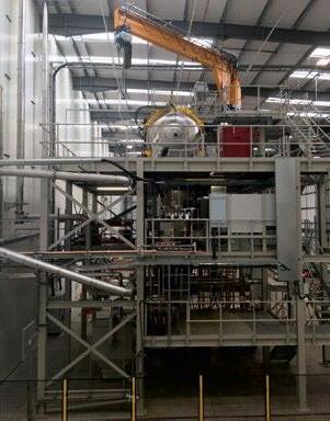
PVA TePla AG, Wettenberg, Germany, has responded to a steady increase in order volumes with the decision to significantly expand production at the company’s headquarters. The company has announced a new production and a logistics hall, with a total of 1,600 m 2, is currently under construction to meet this growing demand.


“We are planning a significant jump in sales for 2023 in our budget, which is definitely backed up by a corresponding personnel plan,” stated Dr Udo Broich, Managing Director of the subsidiary PVA Industrial Vacuum Systems GmbH.
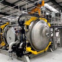
The project involves a construction sum of approximately €3.1 million and is being carried out with the support of the Moos planning office from Wettenberg, Germany.
The construction was begun by a groundbreaking ceremony by the company’s board of management and the managing directors. Construction is expected to be completed in November of this year.
The PVA TePla Group reported it is planning to generate group sales of between €240-260 million this year.

www.pvatepla.com
Munson Machinery introduces Vee Cone Blender for uniform powder blends

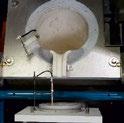
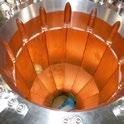
Industrial equipment supplier Munson Machinery, Utica, New York, USA has introduced a 28-litre Vee Cone Blender, the VB-1-S316, which is said to achieve uniform blends of dry bulk solids in a typical 15-30 minutes, with little or no product degradation. The blender is constructed from 316 stainless steel and is available finished to industrial, food, dairy and pharmaceutical standards.
Suitable for laboratory testing, pilot plants or low-volume blending of dry powders and granular materials, the unit reputedly delivers equal homogeneity at fill volumes from 100% to 25% of rated capacity.


Smooth internal surfaces free of baffles, shafts and bearings, are said to allow complete discharge through a 152 mm hand-wheeloperated butterfly valve, eliminating material waste. Access to internal surfaces through the discharge valve and twin doors at the ends of the inclined cylinders permits thorough sanitising in minutes, preventing cross-contamination.
The Vee Cone chamber rotates at up to 30 RPM, driven by a 0.75 kW wash-down motor, imparting a
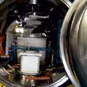
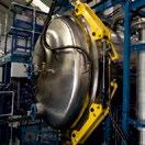
tumbling action that is gentler and less energy consuming than ribbon blenders and other agitated machines in which blades, paddles or ploughs are forced through stationary material.
A safety-interlocked polycarbonate housing is intended to protect operators from the rotating vessel.
An optional intensifier bar can break up soft agglomerates and be equipped with spray ports to distribute liquid additions throughout the batch.
Munson Machinery also offers Vee Cone Blenders in capacities from 8-5,663 litres, as well as a variety of other mixers, blenders and size reduction machinery.
www.munsonmachinery.com
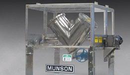
38 PIM INTERNATIONAL SUMMER 2023 © 2023 INOVAR COMMUNICATIONS LTD VOL. 17 NO. 2 | contents | news | events | advertisers | website | newsletter | Industry news Phoenix Scientific Industries Ltd High throughput
atomisation systems Advanced Process Solutions PSI Limited - Apex Business Park Hailsham - East Sussex - BN27 3JU - UK Tel: +44 (0)1323 449001 info@psiltd.co.uk - www.psiltd.co.uk P S I provide excellence in rapid solidification systems to the worldwide A M , S L M , H I P and the renewables industries
gas
For the production of metal powders ContiPour®
Munson Machinery has introduced the VB-1-S316 Vee Cone Blender (Courtesy Munson Machinery)
DIFFERENT ATOMIZATION AND SEPARATION TECHNOLOGIES TO MEET YOUR NEEDS:


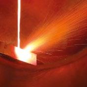
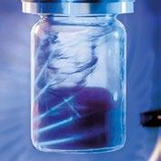
● GAS OR ULTRASONIC ATOMIZATION FOR SPHERICAL POWDERS WITHOUT ANY SATELLITES


Ideal for LPBF, MIM, Binder Jetting and other Additive Manufacturing applications with the need for high quality powders with high purity, sphericity and wide range of reproducible particle size distribution.
● WATER ATOMIZATION FOR MORE IRREGULAR POWDERS Ideal for recycling/re ning process, press & sinter process and others.


● MAXIMUM PURITY BY OXIDATION-FREE PROCESSING in the closed-chamber machine by means of de-gassing, vacuum and protective gas features


● FOR A WIDE RANGE OF METALS AND FOR SMALL TO MEDIUM AMOUNTS AUG series HTC+ gas atomizers with temp. max. up to 2100° C Also versions for high-reactive metals as aluminium or magnesium available!
● AIR CLASSIFIER AC SERIES FOR PRECISE SEPARATION OF METAL POWDERS into ne and coarse powder fractions especially in the range < 25 µm, where conventional sieving operations fail.
● ALL UNITS DESIGNED FOR EASY HANDLING AND CLEANING, QUICK ALLOY CHANGE WITH MINIMUM CROSS CONTAMINATION

39 SUMMER 2023 PIM INTERNATIONAL VOL. 17 NO. 2 © 2023 INOVAR COMMUNICATIONS LTD contents advertisers GETPDF POWDER ATOMIZATION PLANTS · AIR CLASSIFIERS · VACUUM PRESSURE CASTING SYSTEMS CONTINUOUS CASTING SYSTEMS · MELTING MACHINES · GRANULATION SYSTEMS 75045 Walzbachtal · Germany · Phone +49 7203 9218-0 · E-mail: info@bluepower-casting.com
Inert gas
on AC 1000 G Ultrasonic
www.bluepower-casting.com
air classi cation
atomization
Gas Atomization Unit AUG 3000
Gas atomized Ag-based solder alloy powder
& EXPERTISE
BLUE POWER EQUIPMENT
FOR YOUR METAL POWDER PRODUCTION
Ultrasonic Atomizer AUS 500 powered by AMAZEMET
Nexa3D acquires Addifab, launches digital tooling for Injection Moulding
Nexa3D, Ventura, California, USA, has completed its acquisition of Addifab, Taastrup, Denmark, the creator of Freeform Injection Moulding, a proprietary and patented digital tooling process reported to couple the design freedom of Additive Manufacturing with the mechanical performance of injection moulding. The acquisition will add foundational intellectual property and capabilities to Nexa3D’s product line and accelerates its resin formulation and industrial production initiatives.
The deal follows a successful year of collaboration between the two companies in both North America and EMEA. The joint sales and marketing efforts resulted in converting dozens of customers from traditional tooling to digital tooling, thus saving time and cost. This endto-end solution combines Nexa3D’s fast polymer Additive Manufacturing machines with Addifab’s high-impact, high-temperature soluble resins to manufacture complex tools that are compatible with metal and ceramic injection moulding feedstock.
“We are very excited to welcome the entire Addifab team to the growing Nexa3D family of people,
products and partners, democratising access to dissolvable tooling for same day complex moulded parts using the entire range of industrially proven plastics,” stated Avi Reichental, co-founder, chairman and CEO of Nexa3D. “We believe that the market validated strategic fit between our businesses and products, combined with the expanded capabilities in product development, next-gen resin formulation, channel coverage, manufacturing and marketing, will result in significant revenue and accretive growth.”
Addifab developed, patented, and successfully brought to market a proprietary end-to-end digital tooling solution that includes CAD-to-Tool software generator, dissolvable tooling resins, Additive Manufacturing and injection moulding process. The company’s xMOLD resin is compatible with the entire range of off-the-shelf thermoplastic materials, including reinforced high-performance feedstocks. Additionally, metals, ceramics, and silicones are also covered, enabling users of Nexa3D machines to tap into applications that would normally require a larger capital investment. A tool additively manu -
Meteor granted US patent for ‘shell’ formation in Binder Jetting
Meteor Inkjet Ltd, a wholly owned subsidiary of Hybrid Software Group headquartered in Cambridge, UK, which services the industrial inkjet systems market, has been granted US Patent No. 11,625,902 for “Methods and Systems for Shell Formation in 3D Printing.” The ShellPro technology utilises the greyscale of capability of inkjet to offer step-function savings in the energy and materials required to additively manufacture complex parts via Binder Jetting (BJT).
Binder Jet technology often necessitates multiple structural constituents of different densities. One such structure might form a
strong ‘shell’ around the object’s surface, which is typically denser than the object’s interior. Meteor’s ShellPro technology utilises the multiple drop size capacity of greyscale industrial inkjet printheads to more easily create sections of higher or lower density as needed. The technology can also automatically reduce shell thickness for small features, thus improving dimensional accuracy.
“This innovation offers the potential for Additive Manufacturing print systems to use as much as 50% less binder fluid, reduce the energy needed for curing and create 3D objects faster, all without sacrificing quality,”
facturable with the xMOLD resin is soluble, meaning it does not require complex slides and gates, giving customers the ultimate flexibility to test and iterate more frequently. Finally, you don’t have to be a toolmaker to quickly design an injection moulding tool using the Addifab tool maker software or Solidworks.
“Soon after teaming up with Nexa3D, it became increasingly apparent that our combined solution unlocks tremendous opportunities for customers looking to create complex injection moulding tools quickly and affordably. A year into our enormously successful commercial collaboration and dozens of customer implementations with the likes of PepsiCo and Wilson Sporting Goods, I’m thrilled that we are officially joining forces,” added Lasse G Staal, co-founder and Business Development Leader at Addifab.
As part of its growing commitment to EMEA, and in service of its growing reseller partner network, Nexa3D plans to immediately leverage Addifab’s Copenhagen facility as its Customer Experience Centre, inclusive of a product showroom, service and support hub for its European-based customers, and a main warehouse and logistics centre in Europe.
www.nexa3d.com
www.addifab.com
stated Ken Hillier, Meteor’s Director of North America and primary inventor.
ShellPro is included as a standard feature in Meteor’s Met3D software. Met3D offers users a means to convert 3D CAD files such as STL or OBJ to rasterised vector files compatible with inkjet AM machines.
Clive Ayling, Meteor’s Managing Director, added, “Meteor continues to undertake basic research to find and develop ways to improve the functionality, cost, quality and reliability of the industrial inkjet printing process. We are delighted that this invention has been recognised with a US patent and are confident that our ongoing investment in technological innovation will directly benefit not only our OEM customers, but also the industry.”
www.meteorinkjet.com
40 PIM INTERNATIONAL SUMMER 2023 © 2023 INOVAR COMMUNICATIONS LTD VOL. 17 NO. 2 | contents | news | events | advertisers | website | newsletter | Industry news

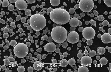
Industry news
Powders for magnetic core and SMD
Powders for MIM
Pre-alloy powders for diamond tools
Powders for auto engine valve seats and guides
Powders for filtering materials Advanced Technology (Bazhou) Special Powder Co.,Ltd No.76 Xueyuan Nanlu, Haidian, Beijing 100081,China Tel: +86-13701029643 Email: powdermetal@atmcn.com www.antai-emarketing.com METAL POWDERS
1958
•
•
•
•
•
SINCE
Sales
POWDERS SINCE
AT&M Expands Capacity To 10000 Tons, Possess 13 Production lines, Focus On Soft Magnetic Powders and MIM Powders, The New Joint Venture Located In Bazhou City,Hebei Province,China Advanced Technology (Bazhou) Special Powder Co.,Ltd No.76 Xueyuan Nanlu, Haidian Beijing,100081, China Tel:+86(10)-62182464 Email:powdermetal@atmcn.com http://www.atmcn.com Burkard Metallpulververtrieb GmbH Tel. +49(0)5403 3219041 E-mail: burkard@bmv-burkard.com Sales Agent in Europe Burkard Metallpulververtrieb GmbH Tel. +49(0)5403 3219041 E-mail: burkard@bmv-burkard.com
STOCK CODE:000969
METAL
1958
Low Pressure Powder Injection Moulding of irregular shaped iron powders shows promise as a lower cost alternative to spherical powders
In the Spring 2023 issue of PIM International (pp 54-58), we reported on a comprehensive survey outlining the significant progress that has been made into researching the potential of Low-Pressure Powder Injection Moulding (LPIM) over the past couple of decades. It was shown that, in addition to being a cost-effective process for prototyping and the small-series production of complex near-net shape components, LPIM has also been successfully used for low and high volume production of highly complex shapes, particularly in the field of ceramics. Some of the key advantages of LPIM compared with high pressure PIM are that LPIM machines are generally smaller in size and use simple hydraulic mechanics, resulting in lower
equipment costs and lower energy consumption. LPIM generally uses a low viscosity (<20 Pa.s) feedstock, which is injected using a pressure 50 to 200 times lower than that used for conventional PIM, resulting in the added benefit of lower mould wear. However, despite the cost advantages of LPIM, current understanding of producing metallic components via LPIM remains limited to only a few proofs of concept.
Included in this LPIM survey was a reference to research at the Ecole de Technologie Superieure, in Montreal, Canada, into the use of irregular shaped iron powders produced by water atomisation for LPIM feedstock. The most recent results from this research work have now been published in the paper: ‘Influence

of powder size on the moldability and sintered properties of irregular iron-based feedstock used in low-pressure powder injection molding’, by A A Tafti, V Demers, and V Brailovski at the Ecole de Technologie Superieure in Montreal, and G Vachon at Rio Tinto Metal Powders, in Sorel-Tracy, Canada, the producer of the water atomised iron powder. The paper was published in Powder Technology Vol. 42, online in March 2023.
The authors stated that earlier research into the mouldability of feedstock using low-cost water atomised iron powder having irregular particle shape demonstrated that LPIM was suitable for fabricating complex green shapes. The influence of powder characteristics and LPIM processing conditions on the sintered density using irregular iron-based feedstocks was also studied. The focus of this current work was, therefore, to study the effect of different particle sizes on LPIM feedstock mouldability and
42 PIM INTERNATIONAL SUMMER 2023 © 2023 INOVAR COMMUNICATIONS LTD VOL. 17 NO. 2 | contents | news | events | advertisers | website | newsletter | Industry news
It’s
matter of choice www.cmfurnaces.com High temp lab and industrial furnace manufacturer to the world 103 Dewey Street Bloomfield, NJ 07003-4237 | Tel: 973-338-6500 | Fax: 973-338-1625 info@cmfurnaces.com
a
also the final microstructures and mechanical performance of parts produced using irregular iron-based powders.

The authors reported that the iron powders were produced using a three-step workflow, comprising water atomisation, high energy attrition milling, and sieving. The attrition milling process, used to reduce the particle sizes, seemed to be responsible for the bimodal distribution of the three powder lots produced: −45, −25, and −10 μm (corresponding to a mesh size of 325, 600, and 1250, respectively). Regarding the screening size, powder −45 μm is said to represent a powder lot consisting of particles that have passed through a 45 μm sieve opening. Table 1 shows the physical properties of the three types of iron powders produced.
The iron powders were mixed with a binder specifically developed for this research, which comprised (vol.%): 1% of SA, 2% of EVA, 2% of CW, and 36–38% of PW, with the PW value being a function of the solid
Table 1 Physical properties of irregular shaped iron powders (From paper: ‘Influence of powder size on the moldability and sintered properties of irregular iron-based feedstock used in low-pressure powder injection molding’, by A A Tafti et al, published in Powder Technology, Vol 420, 5 March 2023, 15 pages)
loadings used for each feedstock. The moulding behaviour of the iron powder feedstocks was assessed in two stages. The first stage assessed the impact of the particle size on the feedstock viscosity and a common solid loading for all the powder lots was set to 57 vol.%. This value corresponds to the maximum workable solid loading of the finest powder used in this study (i.e., −10 μm). The second stage looked at the overall performance of each
powder lot during the LPIM process (i.e., primarily the mouldability and sinterability); the maximum solid loading of each powder lot was used in the feedstock formulation. This powder loading in the feedstock varied from 57–59 vol.%, with a higher solid loading observed as the powders became coarser. The authors found, from their mouldability analysis, that the −10 μm feedstock showed the best moulding potential thanks to its higher feed -
43 SUMMER 2023 PIM INTERNATIONAL VOL. 17 NO. 2 © 2023 INOVAR COMMUNICATIONS LTD | contents | news | events | advertisers | website | newsletter | GETPDF
LIS TECHNOLOGY
3D-printed ceramics: Big parts, thick walls & full density throughout the entire part.
Powder ID Particle size (μm) Span (D90-D10)/ D50 Distribution slope parameter (SW) Pycnometer density (g/cm 3) D10 D50 D90 -45 μm 1.0 13.1 38.6 2.87 1.61 7.4 -25 μm 0.9 10.6 26.0 2.37 1.75 7.1 -10 μm 0.8 5.8 15.6 2.55 1.98 6.9
Industry news
(From paper: ‘Influence of powder size on the moldability and sintered properties of irregular iron-based feedstock used in low-pressure powder injection molding’, by A A Tafti et al, published in Powder Technology, Vol 420, 5 March 2023, 15 pages)
stock homogeneity and a slightly lower solid loading of 57 vol.%. Fig. 1 shows the comparison between the achieved mouldability index and the spiral flow distance achieved in LPIM.
Fig. 2 shows the laboratoryscale LPIM press used to validate the mouldability index and fabricate rectangular parts for tensile tests and density measurements. The injection moulded parts were then debound and sintered using the thermal cycles shown in Fig 3. The thermal cycle for binder removal using a thermal wick-debinding approach, in which the injected parts were placed into a debinding cell and heated under pure argon gas flow (25 L/min), is shown in Fig. 3a. During the first stage of debinding at 250°C, alumina was used as the wicking medium to extract the melted binder out of the part using capillary
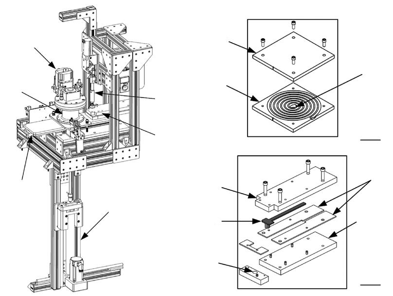
(From paper: ‘Influence of powder size on the moldability and sintered properties of irregular iron-based feedstock
in low-pressure powder injection molding’, by A A Tafti et al, published in Powder Technology, Vol 420, 5 March 2023, 15 pages)
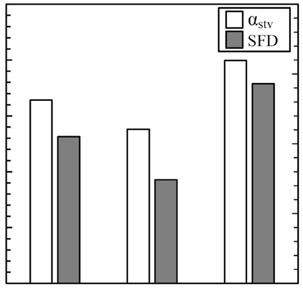
44 PIM INTERNATIONAL SUMMER 2023 © 2023 INOVAR COMMUNICATIONS LTD VOL. 17 NO. 2 | contents | news | events | advertisers | website | newsletter | Industry news
Fig. 1 Comparison between the mouldability index and the spiral flow distance.
Fig. 2 Schematic illustrations of the (a) injection press and mould cavities for (b) spiral and (c) rectangular geometries
Mobility index ( α stv ) α stv SFD Spiral flow distance (mm) Powder lots (a) (b) (c) 500 400 350 300 250 200 480 460 440 420 400 -45 µm -25 µm -10 µm 5 cm 5 cm Gate Gate Mold Upper plate Mold holder Upper plate Lower plate Side plates Injected part Injection cylinder Sliding platform Feedstock container Mixing system Base plate
used
Fig. 3 (a) Thermal wick-debinding cycle under the protective atmosphere of pure argon and (b) sintering cycles under the reactive atmosphere of pure hydrogen (From paper: ‘Influence of powder size on the moldability and sintered properties of irregular iron-based feedstock used in low-pressure powder injection molding’, by A A Tafti et al, published in Powder Technology, Vol 420, 5 March 2023, 15 pages)
forces (segment (i) in Fig. 3a). To activate thermal pyrolysis, the furnace temperature was increased to the pre-sintering temperature of 600°C for which alumina acts as a support for the moulded parts during the final binder burnout and pre-sintering
steps, as shown in segment (ii) in Fig. 3a.
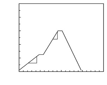
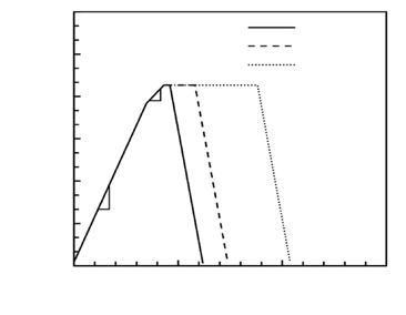
The debound parts were then placed on a zirconia plate before sintering under pure hydrogen gas flow at 1280°C for three sintering times of 30, 90, and 270 min (segment
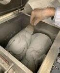
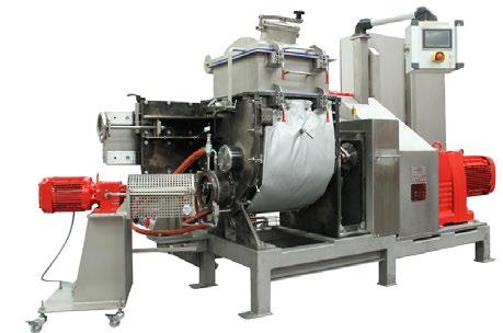
(iii) in Fig. 3b) and then cooled down. Fig. 4 shows the progression of density over the three time periods with the results confirming that, for such irregular shaped iron powders, particle size remains one of the main driving forces for sintering, as can
45 SUMMER 2023 PIM INTERNATIONAL VOL. 17 NO. 2 © 2023 INOVAR COMMUNICATIONS LTD | contents | news | events | advertisers | website | newsletter | GETPDF
World Leading Z Blade Mixers • Easy Clean • Vacuum • Heating • 0.25 - 500 litres Mixer Extruders • Easy Clean • Vacuum • Heating • 2 - 500 litres +44 (0)1256 305600 info@mixer.co.uk www.mixer.co.uk
Z Blade Mixers • Easy Clean • Vacuum • Heating • 0.25 - 500 litres Mixer Extruders • Easy Clean • Vacuum • Heating • 2 - 500 litres
pelletiser World leading MIM Feedstock Mixer/extruders
and pelletising
MIM
CIM feedstock
blades
extrusion screw
Laboratory
discharge
World Leading
Model shows a 75 litre Mixer Extruder with
• Mixing, binding, extruding
for
and
• Easy clean design - fully removable
and
•
& production sizes • Tilt or screw
+44 (0)1256 305600 | info@mixer.co.uk | www.mixer.co.uk
Model shown is a 75 litre Mixer Extruder with pelletiser
Temperature (°C) Temperature (°C) Sintering time (h) Debinding time (h) (ii) (iii) (a) (b) (i) 1000 1800 1500 1200 900 600 300 0 800 600 400 200 0 15 30 40 10 20 5 10 0.8°C/min 5.5°C/min 30 min 90 min 270 min 2°C/min ∼ 1.6°C/min ∼ 13°C/min 0.4°C/min 0 0 Industry news
Fig. 4 Sintered density as a function of sintering time (From paper: ‘Influence of powder size on the moldability and sintered properties of irregular ironbased feedstock used in low-pressure powder injection molding’, by A A Tafti et al, published in Powder Technology, Vol 420, 5 March 2023, 15 pages)
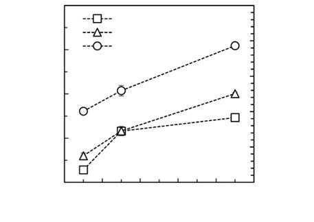
be seen for the -10 μ m specimen, which reached 7.1 g/cm 3 (~90%) after 270 min – the highest density level achieved in this research work. The authors stated that parts produced
by conventional MIM usually reach a sintered density of 95 to 99% of theoretical and the lower level in LPIM of irregular iron powders could be attributed to the suboptimal sintering

conditions used. Following sintering, a linear shrinkage of about 15, 17, and 20% respectively was measured for the -45, −25, and −10 μm powders.
The authors investigated the type of porosity and pore size distribution in the microstructures of the sintered iron LPIM parts, as well as determining the evolution of carbon and oxygen contents during debinding and sintering (Fig. 5 a-b). The results show that, at the final high debinding temperature of 600°C, the oxygen content was reduced to 0.07–0.47 wt.%, whereas the carbon remained relatively constant at 2.7 to 2.9 wt.% during debinding. During sintering (Fig. 5 c-d), it was found that the use of a hydrogen atmosphere for only 30 min reduced the oxygen content by 2 to 16 times and the carbon content by 10 to 80 times, depending on the powder grade . An increase in sintering time from 30 to 90 min was found to further promote oxygen reduction, decreasing the
46 PIM INTERNATIONAL SUMMER 2023 © 2023 INOVAR COMMUNICATIONS LTD VOL. 17 NO. 2 | contents | news | events | advertisers | website | newsletter | Industry news
Sintered density (g/cm 3 ) Sintered time (min) Relative sintered density (%) 7.5 7.0 6.5 6.0 5.5 70 75 80 75 80 85 0 60 120 -45 µm -25 µm -10 µm 180 Sintered at 1280°C in pure hydrogen 240 300
oxygen content from 300 to 200 ppm. An increase in sintering time up to 270 min appears to have a positive impact on the oxygen levels in the −25 μm and −10 μm grade iron powders, with a decrease to 170 and 100 ppm, respectively. The authors concluded that the carbon and oxygen contents of all sintered specimens were within acceptable ranges for pure sintered iron. Finally, the authors looked at the microstructures and mechanical properties of the three grades of irregular iron powder sintered for the three different time periods.
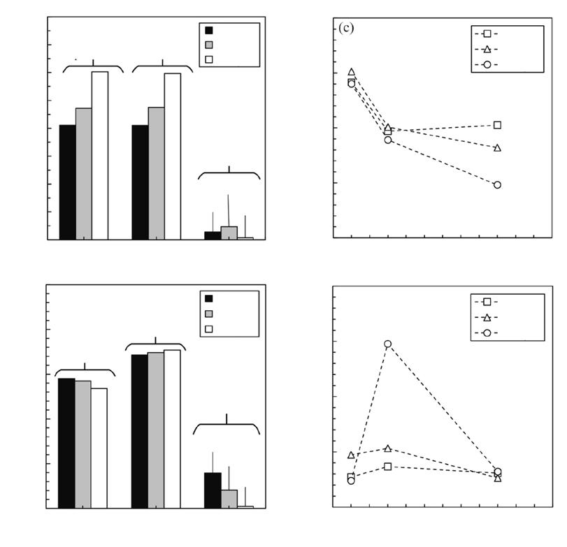
SEM observations confirmed that the microstructures obtained with the −10 μm powder exhibited a more spherical and finer pore network than those obtained with the other two powder grades studied. The fine-grained structure and the presence of pores at the grain boundaries in the −10 μm specimens also suggests that sintering temperature could possibly be increased to complete the microstructure formation and to increase the density and mechanical properties. They stated that optimum sintering conditions still needed to be determined.
In terms of mechanical properties achieved, the -45 μm specimens sintered at 1280°C for 270 min exhibited a final density of 6.2 g/cm 3 , a UTS of 161 ± 7 MPa, a YS of 48 ± 3 MPa, and an EL% of 12%, while the −10 μm specimens, sintered using the same conditions, gave a density of 7.1 g/ cm 3 , a UTS of 225 ± 1 MPa, YS of 73 ± 3 MPa, and an EL% of 24%. These mechanical properties were found to be similar to those obtained with the MIM parts conventionally produced from fine spherical iron powders.
www.sciencedirect.com/journal/ powder-technology
47 SUMMER 2023 PIM INTERNATIONAL VOL. 17 NO. 2 © 2023 INOVAR COMMUNICATIONS LTD | contents | news | events | advertisers | website | newsletter | GETPDF Industry news
Fig. 5 Evolution of oxygen and carbon contents during (a-b) debinding and (c-d) sintering processes (From paper: ‘Influence of powder size on the moldability and sintered properties of irregular iron-based feedstock used in low-pressure powder injection molding’, by A A Tafti et al, published in Powder Technology, Vol 420, 5 March 2023, 15 pages)
Debinding temperature (°C) Debinding temperature (°C) Sintering time (min) Sintering time (min) Oxygen content (wt.%) Oxygen content (wt.%) Carbon content (wt.%) Carbon content (wt.%) (a) (c) (b) (d) 0 0 0.04 8 7 6 5 5 RT 0 0 90 90 180 180 270 270 360 360 RT 250 250 600 600 4 4 3 3 2 2 1 1 0 0 0.04 0.03 0.03 0.02 0.02 0.01 0.01 -45 µm -45 µm -45 µm -45 µm As-received powder As-received powder Capillary extraction Capillary extraction Binder burnout Binder burnout 0.47 0.28 0.07 0.05 0.41 0.79 -25 µm -25 µm -25 µm -25 µm -10 µm -10 µm -10 µm -10 µm
HP’s novel coating that could enable the free sintering of BJT and MIM parts
Metal Binder Jetting (BJT) involves the selective application of a binder layer-by-layer on a powder bed to produce green parts, followed by debinding and sintering treatments. During the debinding and sintering processes, the binder burns out, particle-to-particle necking initiates, and the bonding cross-sectional area increases as sintering progresses. An increase in the bond area leads to an increase in brown part strength. However, the overall tensile strength is compromised due to the prevailing elevated temperature, as a result the parts with overhang features distort/sag under gravity. Traditional methods used to avoid part sag are sintering with live setters or using machined ceramic setters. Distortion/ sag during the sintering of binderpowder systems, including MIM and
BJT, is inherent and is a fundamentally challenging scientific research problem.
In the open literature, there have been no practical solutions available to sinter as-printed green parts without the use of support structures. Recently, John Samuel Dilip Jangam, Thomas Anthony, Jim McKinnell, Ben Pon, Jake Piderman, and Lihua Zhao, at HP Inc.’s HP Labs invented a shape-retainingstimulus coating that eliminates the need for support structures during the sintering of copper and stainless steel parts created by Binder Jetting. Their research was published in Solid Freeform Fabrication 2022: Proceedings of the 33 rd Annual International Solid Freeform Fabrication Symposium, with the paper ‘Support-free sintering of 3D
printed binder jet copper and stainless steel parts’, pages. 1494–1505.
In their study, a simply supported configuration with spans of 28 mm, and 50 mm for copper and 33 mm for stainless steel were used. To ascertain the progress of distortion/ sag in copper parts with temperature, the green parts were thermally processed at 500°C to 1040°C. Their results showed an increase in the angle of deflection/distortion from 0° to 20° with an increase in the treatment temperature. Copper green parts were sintered at 1040°C for 4 h in ArH 2, and stainless steel green parts were sintered at 1370°C for 2 h, also in ArH 2. Fig. 1 shows copper and stainless steel parts before and after sintering. Sintered parts showed a deflection of 20° for copper and 13° for stainless steel.
Shape-retaining-stimulus coatings (SRSC) were developed to resist part sag during sintering. SRSC-Cu developed for copper was applied to the green part surfaces (Fig. 2a) and sintered at 300°C for 1 h + 500°C for 2 h + 650°C for 1 h + 1000°C for 30 min, in ArH 2. Fig. 2b shows the sintered part with a 28 mm overhang stayed intact without sag. These results profoundly elucidate that SRSC-Cu could eliminate part sag during sintering. Interestingly, SRSC coating on the part surfaces can be cleaned by brushing off or sand blasting (Fig. 2 c). It was also reported that a part with a 50 mm overhang remained intact without sag after sintering.
By subjecting the coated green parts to various thermal treatment temperatures, the authors were able to better understand the mechanism of support-free sintering. According to their findings, the coating forms a strong metallurgical bond with the part surfaces and avoids sagging when treated at 300°C for 1 h + 500°C for 2 h. Concurrently, multistage sintering helps to increase the volume of particle-neck-bond providing strength to support itself. When the coated part is heated to 600°C, a chemical reaction in the coating causes it to transform into a
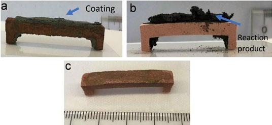
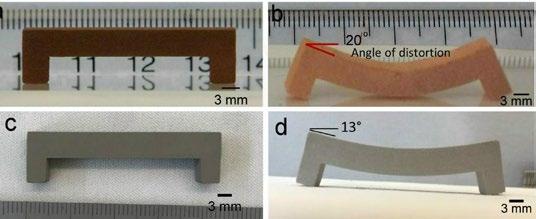
48 PIM INTERNATIONAL SUMMER 2023 © 2023 INOVAR COMMUNICATIONS LTD VOL. 17 NO. 2 | contents | news | events | advertisers | website | newsletter | Industry news
Fig. 1 (a) Copper green part (b) sintered copper part showing severe sag
(a)
(c) stainless steel green part and (d) sintered stainless steel part showing severe sag
Fig. 2 (a) Green part (28 mm span) with SRSC-Cu coating, (b) sintered part and (c) sintered part after cleaning
Coating (b) (c) (d) (a) (b) (c)
Reaction product

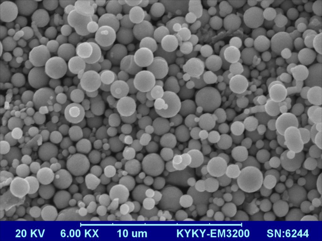
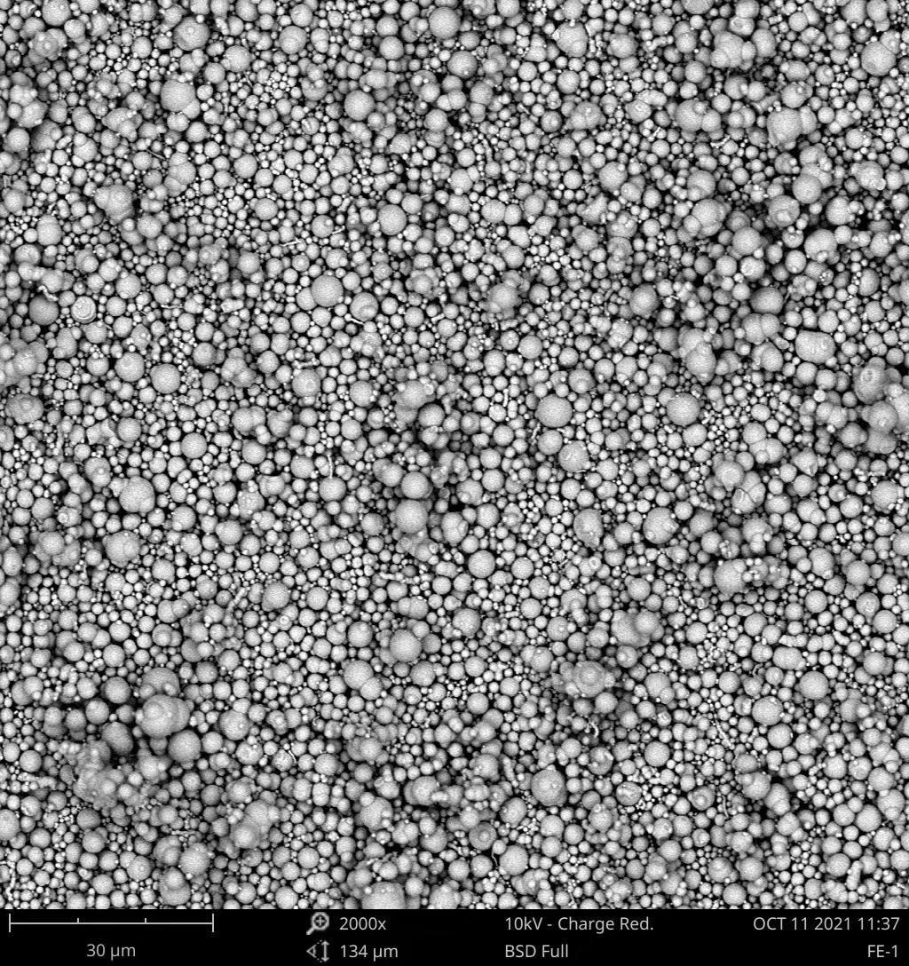
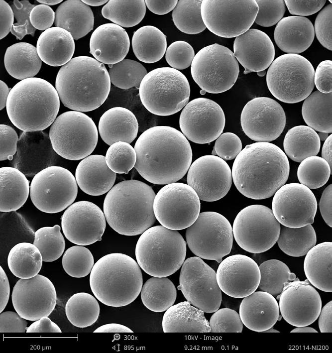
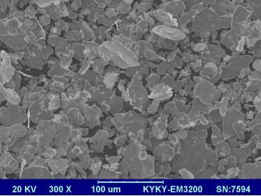
Soft Magnetic Powder Carbonyl Iron Powder Atomized Alloy Powder Microwave Absorbing Material www.yueanmetal.com oversea@yueanmetal.com
porous network, adhering to the part surfaces. In their paper, additional experimental results on parts with overhangs at 30°, 45°, and 60° angles were reported to have sintered without sag.
The researchers also investigated support-free sintering of 316L stainless steel parts. SRSC-steel coating,
developed for stainless steel, was applied to the green part surfaces, and sintered. Fig. 3 shows green part with SRSC-steel coating (a), after sintering (b) and after cleaning (c).
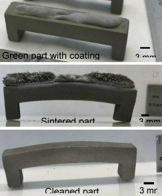
The stainless steel sintered part showed no sag. During the initial stages of debind/sintering, the SRSC ingredients metallurgically bond to
the part surfaces and provide the necessary strength to prevent sag under gravity. Similar to SRSC-Cu coating, SRSC-steel coating undergoes a chemical reaction while sintering, and the reaction product is weakly adhered to the part. However, the morphology observed was different. After cleaning and sand blasting there were no traces of prior coating application.
During the development of these shape-retaining-stimulus coatings, certain coating mixture combinations were found to induce positive deformation while sintering. These coatings caused the part to curl up, moving against gravity and countering the natural phenomenon of part sag. With an optimised coating formulation, the researchers were able to tune the extent of deformation in the part. Fig. 4 shows that the shapeinducing-stimulus coating can add a new dimension to the copper green part during sintering. Researchers described this intriguing new phenomenon as ‘4D Metal Printing’, since 3D printed green part is transformed to a new shape by an external stimulus coating during sintering. Further, it was mentioned that shape-stimulus coatings can be extended to make self-assembling metal structures, and the details can be obtained from US patent #US20220226892A1.
In summary, a novel approach was invented to address the sag problem during sintering. Introducing shape retaining and shape inducing coatings can overcome the design limitations and open new opportunities in both the Binder Jetting and MIM industries. www.hp.com/us-en/hp-labs.html
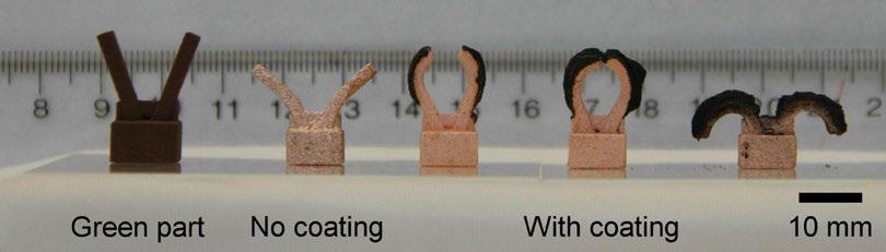
50 PIM INTERNATIONAL SUMMER 2023 © 2023 INOVAR COMMUNICATIONS LTD VOL. 17 NO. 2 | contents | news | events | advertisers | website | newsletter | Industry news
Fig. 3 (a) Stainless steel green part (33 mm span) with SRSC-Steel coating, (b) sintered part and (c) sintered part after cleaning
Fig. 4 Copper parts with shape-inducing-stimulus coating show that
a controlled amount
of
deformation can be induced
in a 3D printed part during sintering
Green part No coating With coating 10 mm (b) 3 mm (a) (c) Sintered part Cleaned part 3 mm 3 mm
part
Green
with coating


Visit us at FAKUMA Friedrichshafen, Germany October 17 – 21, 2023 Stand B4 – 4206
Characterisation of ceramic injected moulded biocompatible oxide ceramic parts
There has been a significant increase over the past fifty years in the number of elderly people in the global population, which in turn has led to the need to raise awareness of osteoporosis caused by ageing and the growing demand for artificial bone materials as bones become more fragile and fracture and require to be repaired or replaced.
Bioceramics is a class of materials that have found use as artificial bone materials for repairing or replacing damaged bone tissue because of their excellent biocompatibility and mechanical properties. Bioceramics can also directly interact with the surrounding tissue, either supporting tissue growth or inducing new tissue regeneration. In many biomedical applications,
bioceramics such as alumina must often be fabricated to a specific and often complex shape such as artificial hip joints, artificial knee joints, bone screws, maxillofacial reconstruction, dental implants, etc. Alumina oxide is a bioinert material with excellent biocompatibility and mechanical properties, but its high hardness and brittleness make it difficult and costly to machine to the highly complex and precision shapes often required in artificial bone replacements.
Ceramic Injection Moulding is a manufacturing process which can meet many of the requirements for complex geometries and high precision alumina components for artificial bone materials and, where necessary, the alumina parts can
be easily machined to the required shape in the green state after injection moulding and prior to sintering. This can result in lowcost custom-made alumina artificial bone structures that match the exact shape of the defective bone being replaced. The CIM alumina parts can also be produced with some porosity to allow cell ingrowth and tissue regeneration.
Research at the Department of Mechanical Systems Engineering, Tokyo Metropolitan University, Japan, has been focused on Ceramic Injection Moulding to produce alumina artificial bone material and, in particular, the research has investigated the effects of CIM conditions, such as alumina powder loading and binder composition and content in the CIM feedstock, in order to control the porosity, grain size and mechanical properties of the sintered CIM alumina material. A paper by T Osada, Y Nagai, and S Kobayashi, recently published
VISOTTICA GROUP YOUR PARTNER FOR CUSTOMIZED COMPONENTS
A technology hub of the highest level and unique worldwide in terms of capacity and technology.
Molds, MIM Metal Injection Molding, CIM Ceramic Injection Molding, Cnc Milling, Zamak Injection.
Know more: visotticagroup.com/meccanica-di-precisione
Visottica Industrie S.p.a.
Via Vecchia Trevigiana,11
31058 Susegana
Treviso, Italia
52 PIM INTERNATIONAL SUMMER 2023 © 2023 INOVAR COMMUNICATIONS LTD VOL. 17 NO. 2 | contents | news | events | advertisers | website | newsletter | Industry news
in Open Ceramics (Vol. 13, 2023, 100328, 7pp) entitled: ‘Fabrication and mechanical characterization of biocompatible oxide ceramic parts by injection molding’, outlined the results of their research. The authors stated that it is possible to control the density of CIM alumina parts by controlling the binder components and amount of binder added, or adjusting the powder loading. Even if the obtained bending strength of the CIM alumina parts decreased slightly with increasing porosity, they stated it was still found to be sufficient for use as artificial bone material.
The authors used alumina (Al 2O 3) powder, to which was added the binder comprising polyacetal (POM) and polyolefin (PO), three types of polypropylene (PP) with different melt flow rates, low-density polyethylene (LDPE) and high-density polyethylene (HDPE)), paraffin wax (PW), fatty acid amide, and an antioxidant. POM and PO acted as the


backbone polymers. Powder loading and binder composition are shown in Table 1.
The alumina powder and binders were mixed in a kneader for 1 h at 180°C with powder loading of 47, 50, and 52 vol.%. Viscosity measurements were performed on the feedstock compounds obtained to investigate their rheological behaviour. The authors stated that it was possible to select the powder loading and binder composition according to the viscosity of the sample. In particular, PP has higher strength and lower viscosity than LDPE and HDPE, which they suggest gives it advantages when used to produce artificial bone material from alumina.
The alumina feedstock was injection moulded into tensile bar shaped specimens. It was established that the optimum conditions for CIM of the alumina feedstock are 50–52 vol.% powder loading or 30–40 mass% in POM/PP and


53 SUMMER 2023 PIM INTERNATIONAL VOL. 17 NO. 2 © 2023 INOVAR COMMUNICATIONS LTD | contents | news | events | advertisers | website | newsletter | GETPDF Industry news Your choice when it comes to state of the art economical sinter plates Keralpor Tel.: +49 (0) 96 45 - 88 300 www.kerafol.com/cts cts@kerafol.com Homogenous shrinkage Keralpor 99 Fine-grained texture Good thermal shock resistance for MIM CIM & 3D-Printing Good heat dissipation debinding no discolouration Keralpor S Good flatness tape casted robot handling charging smooth surface no discolouration sintering automation High reliability laser cutting no irritations no sticking October 1 - 4, 2023 EURO PM 2023 Lisbon, Portugal Booth 73 SAVE THE DATE
Feedstock Label Ceramic Powder [vol.%] Mixing Ratio of Binder [mass%] Alumina POM PO PW Fatty Acid Amide Antioxidant AS-47-30/H 47 30 30 35 4.8 0.2 AS-47-30/M 47 30 30 35 4.8 0.2 AS-47-30/L 47 30 30 35 4.8 0.2 AS-50-30/H 50 30 30 35 4.8 0.2 AS-50-30/M 50 30 30 35 4.8 0.2 AS-50-30/L 50 30 30 35 4.8 0.2 AS-52-30/H 52 30 30 35 4.8 0.2 AS-52-30/M 52 30 30 35 4.8 0.2 AS-52-30/L 52 30 30 35 4.8 0.2 AS-50-30/LDPE 50 30 30 35 4.8 0.2 AS-50-30/HDPE 50 30 30 35 4.8 0.2 AS-50-40/LDPE 50 40 40 15 4.8 0.2 AS-50-40/HDPE 50 40 40 15 4.8 0.2 AS-50-45/LDPE 50 45 45 5 4.8 0.2 AS-50-45/HDPE 50 45 45 5 4.8 0.2
Table 1 Compositions of the alumina feedstock (From paper: ‘Fabrication and mechanical characterization of biocompatible oxide ceramic parts by injection molding’ by T Osada et al, Open Ceramics, Vol 13, 2023, 100328, 7 pp)
POM/PE in the binder composition. Bending strength was measured on both the green and sintered CIM alumina parts. Fig. 1 shows the relationship between relative density and bending strength in sintered samples, depending on the effect of powder loading, and Fig. 2 shows the same relationship, depending on the different binder compositions used.
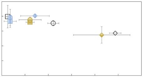
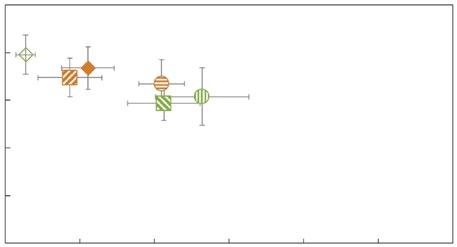
The authors reported that the higher viscosity of PP, which has the higher bending strength, makes this binder more suitable when the green CIM parts need to be machined before sintering. The bending strength of LDPE specimens increased with increasing POM and LDPE content. The authors suggested that the molecular weight or content of the backbone polymer affected the strength of green CIM alumina compacts.
Porosity of the sintered CIM alumina parts could be modified by changing the powder loading and porosity could also be increased when needed by increasing the backbone polymer content. Higher powder loading was found to show larger grain sizes in sintered alumina, whereas parts with lower powder loading showed smaller grain size and higher porosity. Bending tests showed fracture occurring along the grain boundaries. The bending strengths of the CIM alumina specimens showed that they were sufficient for use as artificial bone material.
www.sciencedirect.com/journal/ open-ceramics


54 PIM INTERNATIONAL SUMMER 2023 © 2023 INOVAR COMMUNICATIONS LTD VOL. 17 NO. 2 | contents | news | events | advertisers | website | newsletter | Industry news
Fig. 1 Relationship between relative density and bending strength of CIM sintered alumina with different powder loading (From paper: ‘Fabrication and mechanical characterization of biocompatible oxide ceramic parts by injection molding’ by T Osada et al, Open Ceramics, Vol 13, 2023, 100328, 7 pp)
Porosity (%) Porosity (%) Bending strength (MPa) Bending strength (MPa) 500 500 400 400 300 300 200 200 100 100 0 0 0 0 2 2 AS-47-30/H AS-47-30/M AS-47-30/L AS-52-30/H AS-52-30/M AS-52-30/L AS-50-30/H AS-50-30/LDPE AS-50-40/LDPE AS-50-45/LDPE AS-50-30/HDPE AS-50-40/HDPE AS-50-45/HDPE AS-50-30/M AS-50-30/L 4 4 6 6 8 8 10 10 12 12 Read all back issues of PIM International for free www.pim-international.com
Fig. 2 Relationship between relative density and bending strength of CIM sintered alumina with different binder compositions (From paper: ‘Fabrication and mechanical characterization of biocompatible oxide ceramic parts by injection molding’ by T Osada et al, Open Ceramics, Vol 13, 2023, 100328, 7 pp)
TianyiMetalUltrafine Powder Co., Ltd
Carbonyl Iron Powder
Gas Atomised Alloy Powder
Hybrid Gas-water Atomised Alloy Powder
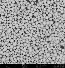

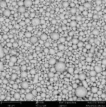
ISO 9001:2015
ISO 14001
IATF 16949
We offer standard and tailored Carbonyl Iron Powder, Gas Atomised and Hybrid Gas-water Atomised Alloy and Amorphous Powders used for metal injection moulding parts; inductive electronic components with excellent resistance to salt spray, high temperature and humidity; electromagnetic shielding and microwave absorption; diamond tools and high-density tungsten alloy; additive manufacturing and laser cladding.
In addition, we produce metallo-organic compounds such as iron pentacarbonyl Fe(CO)5, diiron nonacarbonyl Fe2(CO)9, triiron dodecarbonyl Fe3(CO)12, tungsten hexacarbonyl W(CO)6
Address: No. 166, Yingchun Rd, Xuyi, Huai’an 211700, Jiangsu, China Tel: +86-517-88434888 \ 88701888 \ 88434166 Mobile: +86-17388415059
Email:a1@tycx.cn | jrtyc@189.cn
Website: www.cip-world.com | www.tycx.cn

MIM 316L stainless steel mechanical properties compared with other forming processes
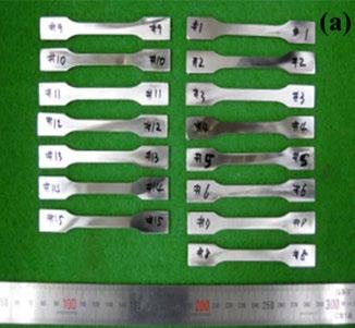
316L stainless steel is one of the most commonly used alloys in Metal Injection Moulding thanks to its excellent corrosion resistance, weldability and good mechanical properties. Typical applications consist of consumer products such as watchcases, spectacle frame parts, automotive components, electronics, dental and medical devices. MIM 316L stainless steel is said to have contributed significantly to the growth of the global MIM industry, which has seen average annual growth rates of around 14% over the past decade.
However, whilst MIM technology has advantages in terms of achieving shape complexity with minimum material waste in processing compared with other shaping processes, such as machining, investment casting and die casting, the mechanical properties of MIM 316L stainless steel are very much dependent on optimising the MIM process. In particular, mechanical properties of MIM 316L stainless steel are highly dependent on the final density and grain size achieved in the sintered parts and any defects occurring during the MIM process
can have a detrimental effect on final properties.
Research at the Chungbuk National University, in Cheongju, and the Industrial Materials Processing R&D Department at Korea Institute of Industrial Technology (KITECH), in Incheon, Republic of Korea, has been undertaken to achieve a greater understanding of the mechanical properties, including fatigue strength, of MIM 316L stainless steel. The aim of the research was to allow MIM 316L stainless steels to be considered for application sectors requiring higher strength components, for example in agricultural machinery. The results of this research have been published in Materials, March 7, 2023, Vol 16, 2144, 12 pp, with the authors I-S Hwang, T-Y So, D-H Lee, and C-S Shin.
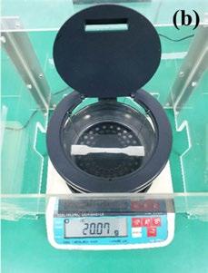
The authors stated that fifteen test bars were injection moulded from 316L stainless steel feedstock based on water atomised grade powders, with the test bars being debound at 900°C for 1 h in hydrogen followed by sintering at 1320°C for 2 h under vacuum. The mechanical properties of the sintered MIM 316L test bars were then compared with 316L
cold-rolled parts and also with some 316L parts made by hot rolling or by PBF-LB Additive Manufacturing. The authors analysed the microstructure of the sintered 316L test pieces via scanning electron microscopy (SEM) and the grain size using the intercept method and EBSD calculations. Fig. 1 (a) shows the 316L specimens made by the MIM process.
The average density obtained in the sintering of the MIM 316L test pieces, measured using the Archimedes principle,was 7.56 g/ cm 3 , or 94.62% of theoretical. The authors suggested that the density achieved in the MIM process is greatly affected by the conditions of the binder composition in the 316L feedstock and the debinding and sintering processes, and that the lower sintered density compared with the cold rolling process could put the MIM 316L parts at a disadvantage in terms of mechanical properties. Fig. 1 (b) shows the electronic densimeter (md-200s) used to measure density.
Tensile testing (UTS) of the sintered MIM 316L specimens was performed to fracture at the constant speed of 5 mm/min for three specimens each. The fatigue tests were done at the stress ratio of 0.1 and were performed at completely reversed cyclic stresses using the servohydraulic fatigue testing system shown in Fig. 1 (c). The maximum
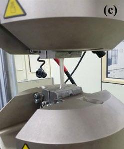
56 PIM INTERNATIONAL SUMMER 2023 © 2023 INOVAR COMMUNICATIONS LTD VOL. 17 NO. 2 | contents | news | events | advertisers | website | newsletter | Industry news
Fig. 1 Process of measuring mechanical properties: (a) specimens produced by MIM process, (b) electronic densimeter (md-200 s), (c) servohydraulic fatigue testing system (Instron 880) (From paper: ‘Characterization of Mechanical properties and grain size of stainless steel 316L via metal injection molding’ by In-Seok Hwang et al, Materials, March 7, 2023, Vol 16, 2144, 12 pp)
(a) (b) (c)
We Smart Focus on Creation and Manufacturing of Titanium Alloy
We Smart Focus on Creation and Manufacturing of Titanium Alloy
After a Storm Comes Titanium
Smart Focus on Creation and Manufacturing of Titanium Alloy
We Smart Focus on Creation and Manufacturing of Titanium Alloy

At JSJW New Material, we’ve been committed to researching titanium and its alloys since our establishment. Thanks to our unique IPCA gas atomisation technology, we’re able to provide the Additive Manufacturing industry with high-quality, lightweight, spherical powder in various particle sizes that boasts good sphericity, high fluidity, and biocompatibility, satisfying the needs of various industries.
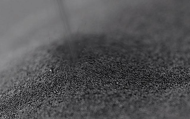
Titanium has become the go-to metal in the aerospace, medical, automotive, cycling, 3C, and other high-value industries due to its high mechanical properties, strengthto-weight ratio, and superior corrosion resistance when compared to other metals. As a key raw material, titanium powder plays a crucial role in achieving these benefits. The benefits of titanium extend beyond AM. We also offer services to mainstream mobile phone brands, including preliminary process research and development, MIM feedstock development, and post-processing.
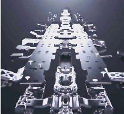
Our title, “After a Storm Comes Titanium,” reflects the major breakthroughs and applications of titanium and its alloys in additive manufacturing in 2023, which will fuel demand for materials and technical support in the AM and MIM industries.
Our in-house manufacturing and innovative IPCA technology for metal powder manufacturing will provide cost-effective raw materials to the industry and increase profit margins for customers.
None of this would be possible without the imagination of engineers – that’s why we welcome discussion on MIM and AM.
JSJW TITANIUM
JSJW TITANIUM
A METAL POWDER & SOLUTIONS PROVIDER
JSJW NEW MATERIAL CO., LTD. NO.56, E. JICHUAN RD., TAIZHOU, P.R.CHINA www.jsjinwu.com
JSJW TITANIUM
We sincerely invite agents worldwide to grow together. info@jsjinwu.com
JSJW TITANIUM
Fig.
‘Characterization of Mechanical properties and grain size of stainless steel 316L via metal injection molding’ by In-Seok Hwang et al, Materials, March 7, 2023, Vol 16, 2144, 12 pp)
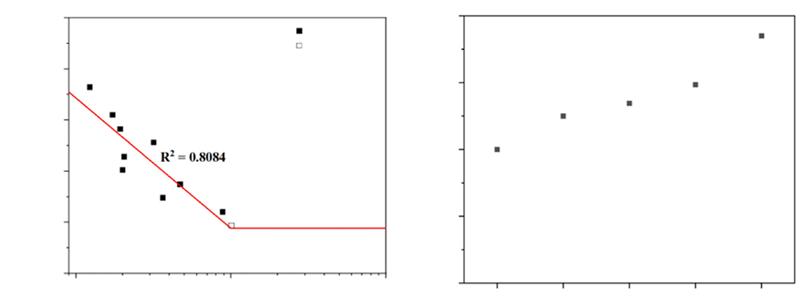
mens was measured at 92%, which is a considerable increase compared to that of the cold-rolled specimen (30%) and was slightly higher than the hot-rolled specimen at 89%. Ductility could be increased further with an increase in sintering temperature to decrease porosity in the sintered material. However, the authors stated that sintering at excessively high temperatures could result in a decrease in ductility due to abnormal grain growth and the precipitation of carbides in the grain boundary. The temperature of 1320°C was therefore found to be optimal, with the sintered microstructure observed using SEM after etching showing average grain size to be 88.51 μ m
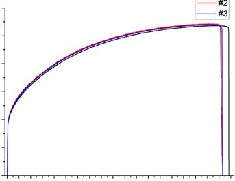
stresses of the fatigue tests were set based on the UTS obtained in the tensile test. These stresses were set at 80% (432 MPa) and in increments down to 55% (297 MPa). The fatigue limit was determined as the stress value applied when the number of loading cycles went beyond 10 6 in this study.
The average UTS value obtained from three of the MIM 316L samples tested was 539 MPa (Fig. 2). This is lower than the tensile strengths of the cold-rolled 316L specimens,

which ranged from 620 to 795 MPa, and lower also than the hot-rolled specimen (580 MPa). Two mechanisms were identified by the authors as the primary causes of reduced mechanical properties in MIM 316L. The presence of pores in the sintered specimens caused by: (1) reduction in the area where stress is applied and (2) polygonal pores caused a notch effect, which could potentially lead to early material failure. The ductility, or elongation to fracture, of the MIM 316L speci -
Fatigue testing was done on ten of the sintered MIM 316L test pieces. The fatigue test was performed at 80% of maximum tensile strength and a stress ratio of R = 0.1. The fatigue life was found at 55% (297 MPa) of maximum tensile strength that achieved 10 6 cycles. Fig. 3 (b) shows the results of the fatigue limit measurements for the MIM 316L and also the fatigue limits for rolled 316L and specimens produced by the PBF-LB Additive Manufacturing process. The fatigue limit for MIM 316was found to be higher than PBF-LB 316L and lower than cold-rolled 316L.
www.mdpi.com/journal/materials
58 PIM INTERNATIONAL SUMMER 2023 © 2023 INOVAR COMMUNICATIONS LTD VOL. 17 NO. 2 | contents | news | events | advertisers | website | newsletter | Industry news
2 Stress-strain curve of 316L produced by MIM (From paper:
Strain (%) Cycle to failure (N) R 2 = 0.8084 Stress ( σ max , MPa) Fatigue limit (MPa) Stress (MPa) (a) (b) 0 100 200 300 400 500 600 0 10 20 30 40 50 10 5 250 0 100 200 300 400 300 350 400 450 500 10 6 Failure Non-failure 10 7 PBF-LB Wang, 2021 PBF-LB
PBF-LB
60 70 80 #1 #2 #3 90
Fig. 3 (a) Stress–life curve of SS 316L produced by MIM (b) Fatigue limit measurement results reported in the literature and in this work for 316L (From paper: ‘Characterization of Mechanical properties and grain size of stainless steel 316L via metal injection molding’ by In-Seok Hwang et al, Materials, March 7, 2023, Vol 16, 2144, 12 pp)
Kalentics, 2020
Spierings, 2013 MIM Rolled
CHINA’S LEADING SUPPLIER OF MIM POWDERS
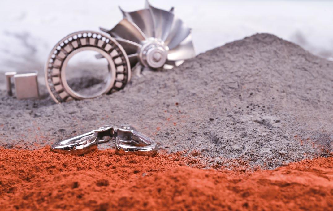
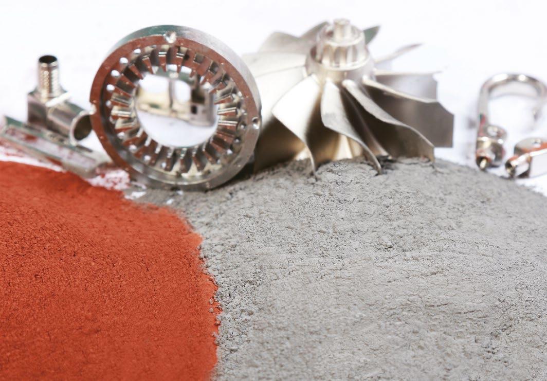
ADOPTING ADVANCED GAS AND WATER
COMBINED ATOMIZATION TECHNOLOGY

WORLD PM2024 in YOKOHAMA Japan
a better world with PM” WORLD PM2024
Metallurgy 13-17 October 2024 YOKOHAMA, JAPAN The World Congress on Powder Metallurgy was held in Asia in 2006 in Busan, South Korea, in 2000 in Kyoto, Japan, and in 2012 in Yokohama, Japan. It is an excellent opportunity to exchange the latest information and deepen friendships in Yokohama Japan. Advanced technologies and information for "Carbon Neutral", "Electrification" and "Energy Saving" www.worldpm2024.com European Powder Metallurgy Association (EPMA) Metal Powder Industries Federation (MPIF) Asian Powder Metallurgy Association (APMA) Supported by Japan Powder Metallurgy Association (JPMA) Japan Society of Powder and Powder Metallurgy (JSPM) Organized by
“Make
Congress & Exhibition International Powder
Evaluating Metal Injection Moulding as a green production technology
Sustainability is a topic that concerns all of us, from individuals to societies and industries. As we face increasingly difficult environmental challenges, discussions about sustainability and our contribution towards it are ongoing in many areas of our daily lives. This is, of course, also true for the Metal Injection Moulding industry. Whilst MIM is already considered a green technology compared to alternative processes, there are still considerable opportunities for improvement that can be identified through life cycle assessment and carbon footprint analysis. Dr Frank Petzoldt and Dr Sebastian Boris Hein consider the complex task of evaluating MIM as a green technology within this context.


than that of other manufacturing processes, the production of metal powders and binders still requires a significant amount of energy
and generates a large amount of waste. The use of solvents and other chemicals in MIM processing can also negatively impact the environment. To reduce this impact, it is important to analyse energy consumption and waste generation in the manufacturing process and make improvements based on that knowledge.


This article takes a closer look at the MIM process chain, reflects on the European MIM community’s take on developing the sustainability of MIM in the coming years, and considers life cycle assessment (LCA) and carbon footprint (CF) analysis as means for evaluating MIM technology.


61 SUMMER 2023 PIM INTERNATIONAL VOL. 17 NO. 2 © 2023 INOVAR COMMUNICATIONS LTD website | newsletter | GETPDF
Fig. 1 The seventeen Sustainable Development Goals set by the United Nations (Courtesy United Nations)
Towards green MIM production
Sustainable Development Goals
In 2015, the United Nations formulated seventeen Sustainable Development Goals (Fig. 1). These goals serve as a blueprint to facilitate a peaceful and prosperous future for people and the planet.
Sustainable MIM
Because these objectives are interlinked on many levels, they can easily be connected to manufacturing technologies such as MIM. Two goals,
9 and 12, which deal with building resilient infrastructure, promoting inclusive and sustainable industrialisation, fostering innovation and ensuring sustainable consumption and production patterns, are clearly linked to MIM (Fig. 2).
In recent years, these goals have been considered more closely by the European MIM community. In a 2021 European Powder Metallurgy Association (EPMA) workshop, attended by a large number of representatives from the European MIM industry, participants exchanged
views on important factors for MIM with regard to digitalisation, quality and sustainability. The results of the discussion were put into a roadmap that reflects the vision of the European MIM community for the coming years (Fig. 3).
As the figure shows, actions at the time focused mainly on waste, material and energy reduction, as well as the use of green energy. The use of LCA to properly assess the sustainability of products seems to be an important next step for future years.
Future improvements in MIM
Of course, in order to improve on a situation, it must first be properly understood. As process capability improves, use cases for MIM will increase; in the long run, many factors may come together to create an ‘ideal’ MIM part. Although such an ideal part and the factors that influence it may be defined in different ways, they can be based on previously mentioned topics, such as LCA, and a deeper understanding of the processes, interactions and requirements of a specified application (e.g., an improved design for an extended period of use, second-life use or recyclability).
62 PIM INTERNATIONAL SUMMER 2023 © 2023 INOVAR COMMUNICATIONS LTD VOL. 17 NO. 2 | contents | news | events | advertisers | website | newsletter |
Fig. 3 Roadmap on sustainable products, processes, and manufacturing plants, developed by members of the European MIM community in 2021
Towards green MIM production
Fig. 2 Goals 9 and 12 are the most relevant to Metal Injection Moulding (Courtesy United Nations)
With regard to processes and manufacturing plants, the use of more sustainable materials and the combination of MIM with Additive Manufacturing are necessary next steps towards green production. This includes using more reliable data collection and generating a deeper process understanding, avoiding trial and error cycles in application development, reducing the necessity of post-processing and the resulting energy wastage, and recycling scrap more efficiently. A very clear common understanding within the group who developed this roadmap was that everything must take the economic perspective into account, ultimately leading to cost reduction.
Given the cost of production, there is a well-known visualisation of the influence that certain stages of manufacturing have in relation to the costs (Fig. 4). Tied to this is the concept of lean innovation, which is based on applying lean principles to create value by smart design and continuous improvement.
This way of thinking already intrinsically and specifically includes a view on sustainability, but, with a clear focus on the specific production environment and associated cost savings (e.g., by minimising waste) it connects the goals of an ideal MIM part and green manufacturing plants and shows the importance of implementing more viewpoints into a product’s design. This also applies to sustainability considerations and must be based on tools that can be used to achieve this.
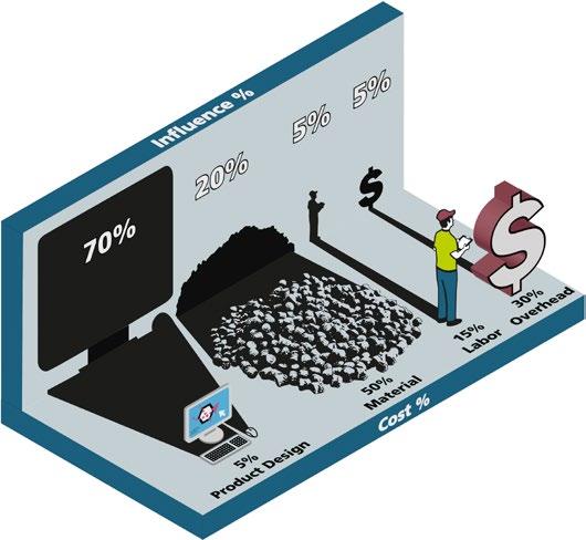
Life cycle assessment
Because LCA is a central tool for approaching sustainability, some core elements and aspects are covered here, as well as the two main ways to make use of it.
Four steps of LCA
LCA is defined as a methodology to assess the environmental impact of a product, process or service throughout its life cycle: from raw material acquisition, through produc -
tion and its use and disposal (or end-of-life use in the case of products). It is a standardised procedure as per ISO standards, mainly ISO 14040 and ISO 14044. The LCA procedure can be divided into four steps:
1. Goal and scope: definition of a product system, functional unit, reference flow, system boundaries, assumptions, limitations, data quality requirements,
allocation procedure, impact assessment and documentation
2. Life cycle inventory (LCI): resources, energy, emissions
3. Impact assessment (LCIA): environmental and human impacts
4. Evaluation/interpretation: definition of priorities, sensitivity analysis, optimisation potentials, balance comparison
63 SUMMER 2023 PIM INTERNATIONAL VOL. 17 NO. 2 © 2023 INOVAR COMMUNICATIONS LTD | contents | news | events | advertisers | website | newsletter | GETPDF
Fig. 4 The influence of production stages on product costs
Towards green MIM production
“This includes using more reliable data collection and generating a deeper process understanding, avoiding trial and error cycles in application development, reducing the necessity for post-processing and the resulting energy wastage, and recycling scrap more efficiently.”
Defining the goal and scope of the LCA is the first step. This is a complex process but provides a framework for the entire analysis and a means to interpret the results, assess the LCA itself and make sensible comparisons with other LCAs. By definition, an LCA encompasses the entire life cycle of the product system; however, there are further variants that use the LCA approach but limit the analysis to certain parts of the product system’s life cycle. Such variants are depicted in Fig. 5.
LCA can be referred to as a cradle-to-grave analysis, but partial LCAs can be done from cradle-togate, eliminating the application
phase in the case of physical products and their end-of-life scenarios (e.g., second-life use, recycling), or from gate-to-gate (e.g., which can focus on a distinct manufacturing part within a product’s life cycle).
LCA in the MIM industry
The MIM industry is primarily focused on providing metal parts. Therefore, assessments that end at the gate are more easily obtained because data about the application stage of parts may be hard to get, depending on the specific product.
The primary use of LCA is as an assessment tool, providing an evaluation of technologies,
products, processes and more. In that respect, it can help in making decisions within developments and be used in consulting, to characterise production systems and analyse optimisation potential. It can also help to select environmental performance indicators and can facilitate communication (e.g., for acquisition), supported by an Environmental Product Declaration, or for marketing, by providing benchmarks.
Essentially, LCA is always used for comparison purposes, such as a comparison of situations at different times (progress), of process A versus process B for a specific product (e.g., MIM vs. investment casting), process variant A versus process variant B (e.g., sintering MIM parts in continuous vs. batch furnaces), design A versus design B, the greenhouse gas (GHG) emissions of process steps (e.g., powder production vs. injection moulding vs. sintering), supplier A versus supplier B or something else.
The second way to use LCA is not only as an assessment tool but as an integral part of the product design (Fig. 6). Because LCA can implement many factors, elements may be included that provide additional value, such as socio-economic factors, political factors such as raw material dependency, or materials and
64 PIM INTERNATIONAL SUMMER 2023 © 2023 INOVAR COMMUNICATIONS LTD VOL. 17 NO. 2 | contents | news | events | advertisers | website | newsletter |
“The primary use of LCA is as an assessment tool, providing an evaluation of technologies, products, processes and more. In that respect, it can help in making decisions within developments and be used in consulting, to characterise production systems and analyse optimisation potential.”
assembly use end-of-life refurbish re-use recycle Towards green MIM production
Fig. 5 LCA and variants
gate-to-gate cradle-to-gate cradle-to-grave raw materials
manufacturing alternatives. When such factors are required for decision making within the design phase of a product, LCA-based scenarios can be integrated into that modelling. Approaches to do this in an automated fashion and thus offering means to optimise a product design based on, or at least including, sustainability aspects, are being increasingly developed.
GHG Protocol
In the late 1990s, an initiative was started to place more emphasis on GHGs with the GHG Protocol. This led to the development of the GHG Protocol Product Life Cycle Accounting and Reporting Standard, which can be regarded as a special form of LCA. It provides “a general framework for companies to make informed choices to reduce greenhouse gas emissions from the products (goods or services) they design, manufacture, sell, purchase or use.”
This clear focus on GHGs has probably influenced the way sustainability is discussed nowadays, particularly in terms of CO 2 emissions as a CF. Emission levels are already determined by many companies, on the one hand to analyse the CF of the company itself in a gateto-gate manner, and on the other hand to provide a product carbon footprint (PCF).
Within the GHG protocol, the scoping (which is the first part of an LCA) is defined in three emission levels, to provide more standardised guidance for companies. Scope 1 emissions are direct emissions generated by the company’s owned or controlled sources. Scope 2 and 3 emissions are indirect emissions, with Scope 2 emissions including indirect GHG emissions from purchased or acquired energy, such as electricity, steam, heating or cooling, generated off-site and consumed by the company. Scope 3 emissions are those that occur in the value chain of a company, as “the result of activities from assets not owned or controlled by the reporting organisation but that the
Design
Disposal Production Use
organisation indirectly impacts in its value chain” - as expressed by the US Environmental Protection Agency. These can be defined as either upstream emissions, related to purchased or acquired goods and services (i.e., cradle-to-gate), or downstream emissions, related to sold goods and services and emitted after they leave the company’s ownership or control (i.e., gate-to-grave).
Scope 3 emissions are manifold and stem from various process elements, and so are often not reliably quantifiable. Therefore, companies are often not expected or required to calculate life cycle inventories for individual products when calculating Scope 3 emissions.
In the following, we look deeper into the technological steps of the MIM process and provide an estimation of the relative impact of process elements on the CF of MIM products.
The MIM process
From a technological view, the core process of MIM is usually depicted as starting with powder and binder, followed by feedstock preparation, injection moulding, first-stage debinding and finally thermal debinding and sintering. When applying the cradle-to-gate view, the acquisition of raw materials, as well as powder and binder production, and secondary operations have to be included. In the following, we will go into a little more detail in these steps regarding selected sustainability aspects and provide the aforementioned estimation, based on the authors’ experience.
Raw material acquisition
The raw materials for a MIM product typically comprise multiple different materials from different sources.
65 SUMMER 2023 PIM INTERNATIONAL VOL. 17 NO. 2 © 2023 INOVAR COMMUNICATIONS LTD | contents | news | events | advertisers | website | newsletter | GETPDF
Fig. 6 Use of LCA as an analysis tool (green arrow), or improvement programme (dark blue arrow)
Towards green MIM production
Metal powders can, of course, be derived from ores that must be processed to gain a pure metal or alloy. The location of natural resources – and, with this, the potential dependencies on certain countries, as well as the conditions of extraction – are topics that should be increasingly considered in the future. These factors already drive politically-motivated approaches to reduce dependencies on problematic sources.
An additional approach is to focus increasingly on recycling to slow down the depletion of natural resources. Also, the more that recycled materials can cover the demand, the fewer the dependencies on potentially problematic resources. However, setting up recycling systems is a complex task, often from a technical perspective alone, but definitely also from a logistical point of view.
Knowledge about the amounts and locations of certain materials in complex systems such as cars, cell phones, etc., as well as how to recover components, is crucial and involves the generation and handling of complex data sets. This may be facilitated by smart designs and approaches to improve the traceability of components (e.g., by tagging), but is certainly a topic for development.
Thus, regarding sustainability, replacing problematic sources, improving raw material acquisition conditions, increasing the amount
of recycled raw materials and, of course, technologically improving the processes can lead to improvements and, for example, lower the CF.
Powder production
There are different processes to produce metal powders, such as oxide reduction, electrolytic deposition or atomisation. Most powders used in MIM are produced by gas or water atomisation. Another powder often employed is carbonyl iron powder, which is produced by the thermal decomposition of carbonyl iron. Water and gas atomisation use molten metal to feed into the media stream of water or gas (typically nitrogen or argon) in which the high shear atomises the melt into droplets that solidify and form the powder particles. The particles are more irregular in water atomisation and usually highly spherical in gas atomisation. Also, water atomised powder usually contains more oxygen, which may have to be reduced later in the process.
Fundamentally, the production of metal powders is an energy-intensive process and thus offers the potential to reduce the CF of powders by using green energy as much as is economically possible. Furthermore, the use of scrap as a raw material source can significantly reduce the CF. The use of large amounts of process media that require a lot of energy in their respective production (e.g., argon) or that must be purified, as in the case of water, add to the CFs of the processes.
Binder component production
Binder components comprise a smaller share of the feedstock, roughly 40% by volume, but are considerably less by weight, due to the greater density of metals. Their specific components differ for different binder systems, but they are always organic compounds. They must be as residue-free as possible during the MIM process chain. Sustainability is a major topic within the chemical industry and has resulted in many ventures to make chemical production more environmentally friendly.
One trend is recycling waste material to break it down into simple chemicals that can act as a base material for a variety of products. An example is the production of polyolefins (e.g., polyethylene, polypropylene), in which cooking oil or residue from vegetable oil production is recycled as a source material. The customer can decide how much of the source material should be used to reduce their CO 2 reductions. Because such approaches have to be built up, they are initially more costly, but they can contribute to minimising the use of oil from fossil sources.
Feedstock production
The production of feedstock is done by using different types of mixing technologies, such as kneading, high-shear mixing and compounding/ extrusion. The reuse of feedstock (e.g., from sprues and runners or defective green parts) may require some additional regranulation to achieve reusable feedstock granulate. Feedstock production may be run continuously, which makes sense for suppliers of large feedstock quantities, but is often done batch-wise, especially when feedstock production is done by part manufacturers in-house.
Because feedstock for MIM is always thermoplastic, the mixing must be done at elevated temperatures to melt the binder completely (i.e., between 120°C and 200°C). Aside from this thermal energy aspect, shear must be applied to homogenise the feedstock as well as possible,
66 PIM INTERNATIONAL SUMMER 2023 © 2023 INOVAR COMMUNICATIONS LTD VOL. 17 NO. 2 | contents | news | events | advertisers | website | newsletter |
Towards green MIM production
“Fundamentally, the production of metal powders is an energy-intensive process and thus offers the potential to reduce the CF of powders by using green energy as much as economically possible. Furthermore, the use of scrap as a raw material source can significantly reduce the CF.”
for which rotating elements such as blades or screws are used against the material’s resistance. This torque, applied via electrical motors, as well as the energy for heating equipment and materials, add to the energy consumption of the MIM process.
Injection moulding
During the injection moulding step, the feedstock is heated and injected into a heated mould to solidify and generate the green part. The two primary types of high pressure injection moulding machines are the more traditional hydraulic machines as well as more modern electricallydriven machines. According to various sources, electrically-driven machines consume less energy, require less maintenance and produce less waste than alternatives such as those using hydraulic oil, which has to be replaced regularly. To increase productivity and reduce the energy required for part production, tools with several cavities can be used. Feedstock can be recycled in-process, as mentioned above, and is usually added to some extent to fresh feedstock in production.
First-stage debinding
In first-stage debinding, the major share of the binder system is removed to form pores through which gaseous decomposition products may leave the parts in the following thermal debinding, without damaging the parts. This removal of binder in first-stage debinding is nowadays mostly done either chemically or catalytically. In chemical debinding, soluble components of the binder system are removed by immersing the green parts in a suitable solvent, usually at elevated temperatures, limited by the boiling point of the solvent.
Suitable solvents depend on the binder system and can be water, acetone, hexane, trichloroethylene, or others. Although some systems can reuse the solvents after distillation, solvents always evaporate during the debinding. Therefore, aside from the energy consumption of the technical equipment, the handling of
solvents is a factor with regard to sustainability. The solubilised and post-distillation collected ‘waste’ of binder components is often disposed of. As the chemical industry is increasingly making use of waste material, improved recycling of these materials may improve the sustainability of the whole process in general.
Catalytic debinding is used for binders based on polyoxymethylene (POM), which are widely used in the MIM industry. POM is chemically decomposed by reacting with nitric acid at elevated temperatures. The resulting toxic formaldehyde is burned off to prevent any harm to people, which results in direct emissions.
First-stage debinding clearly contributes to the emissions, potentially with direct emissions additional to CO 2 equivalents from energy consumption.
Second-stage debinding and sintering
Second-stage (thermal) debinding is often carried out in the same furnace that subsequently sinters the MIM parts. Although this can be done separately, which may lead to parts with lower amounts of residuals, it requires the handling of mechanically highly unstable ‘brown’ (completely debound) parts. The two main options regarding furnace technologies are batch furnaces and continuous furnaces.
Both technologies have technical advantages and disadvantages favouring one or the other. But, from a sustainability perspective, if both technologies were used, continuous furnaces could achieve less energy per part, if the load with parts were sufficiently high, but many more factors must be taken into consideration to determine the ‘best’ option. Because some organic material is typically burned off in the early phase of a furnace cycle, and sometimes hydrogen is used partially or entirely as a sintering atmosphere, the sintering atmosphere is flared after leaving the furnace.
Thus, prolonged high temperatures certainly result in the sintering step being one of the more energy-intensive steps in the MIM process chain.
Secondary processing
For many MIM parts, secondary processing is an integral part of the process chain. The variety of potential secondary operations is very wide, from simple mechanical calibration to adjust the dimensions of distorted parts, to multiple ways to treat the surfaces of parts, machining critical features such as threads, basic heat treatment and Hot Isostatic Pressing (HIP). These secondary processes may lead to further emissions such as removed excess material and certain chemicals, additional to their respective energy consumption, and can contribute considerably to the CF of a part.
67 SUMMER 2023 PIM INTERNATIONAL VOL. 17 NO. 2 © 2023 INOVAR COMMUNICATIONS LTD | contents | news | events | advertisers | website | newsletter | GETPDF
Towards green MIM production
“The variety of potential secondary operations is very wide, from simple mechanical calibration to adjust the dimensions of distorted parts, to multiple ways to treat the surfaces of parts, machining critical features such as threads, basic heat treatment and Hot Isostatic Pressing (HIP).”
Further process-related aspects
Aside from the direct process technologies, there are usually several process-related topics that must also be considered within an LCA, including process-accompanying analytics, data processing, internal logistics and more.
Qualitative impact assessment of the process step
Having looked a little closer into the MIM process steps and some of their respective sustainability aspects, we want to give a qualitative assessment of the contribution of certain process elements to the CF of MIM parts. Given the complexity of LCA and the variability of the process chains of specific MIM parts, Fig. 7 provides an estimation.
As can be seen, the largest contribution is attributed to the powder and potentially to secondary operations. Still, both contain aspects that should be discussed further. For the powder, several sources state the huge impact between virgin powders
and those from recycled materials. Depending on the specific metal or alloy, factors of 2 to 20 can be found concerning the CF between those sources. Of course, the Scope 2 indirect emissions of virgin powders have different aspects, potentially
68 PIM INTERNATIONAL SUMMER 2023 © 2023 INOVAR COMMUNICATIONS LTD VOL. 17 NO. 2 | contents | news | events | advertisers | website | newsletter |
10 9 8 7 6 5 4 3 2 1
Fig. 7 The relative contribution of selected process elements to the carbon footprint MIM parts
powder binder moulding debinding sintering post-processing materials core process secondary
Towards green MIM production
“In principle, the process elements with the largest contribution to the CF are also the ones with the largest potential to reduce it. Still, the relative energy savings potential within each step depends on how well the processes and the technology are optimised, and on potential alternatives, such as in the case of virgin vs. recycled powders.”
related to mining, raw material processing and more, that impact the CF severely.
Secondary operations can also impact the CF significantly, depending on their specific use for a certain product. Heat treatment and HIP may be closer to a sintering process in terms of CF, whereas other operations contribute very little. The binder also contributes considerably, because the synthesis of polymers and other chemicals consumes significant amounts of energy. However, because the CF is usually given based on the weight, the low density of organic materials compared to powders puts them into perspective.
The core MIM production that uses powders and binders (and often feedstocks) within Scope 2 would mainly focus on the elements of injection moulding, debinding and sintering. Some minor post-processing is potentially also included, but processes such as heat treatment and HIP are often outsourced. Within these core steps, sintering contributes most to the CF; injection moulding contributes the least.
In principle, the process elements with the largest contribution to the CF are also the ones with the largest
potential to reduce it. Still, the relative energy savings potential within each step depends on how well the processes and the technology are optimised, and on potential alternatives, such as in the case of virgin vs. recycled powders. Process steps that are rooted in large industries, such as injection moulding, also benefit from developments elsewhere and may be further along with regards to their specific optimisation potential.
When analysing the PCF of a specific MIM part, the actual contribution of the process elements will, of course, be different. But, if more and more companies provide that information, for example, via the Scope 3 approach, the PCF of a final part can be quickly calculated by using the information within the entire MIM customer–supplier chain. This will also provide a more detailed image of the MIM technology and make it more easily comparable to others.
The initial overview of the European MIM community’s vision shows the motivation to take important steps in reducing energy consumption in the coming years. This is already supported strongly by Germany’s MIM Expertenkreis (MIM Expert Group) and the EPMA,
with plans to take further steps with partners from around the globe such as the Japan Powder Metallurgy Association (JPMA) and North America’s Metal Injection Molding Association (MIMA). These actions will contribute to a more sustainable MIM industry as well as greener production plants.
Authors
Dr
Sebastian
Boris Hein Head of Department Powder Technology
Fraunhofer Institute for Manufacturing Technology and Advanced Materials IFAM Wiener Straße 12 28359 Bremen
Germany
www.ifam.fraunhofer.de
sebastian.boris.hein@ifam.fraunhofer. de
Dr Frank Petzodt
Ingenieurbüro Dr. Petzoldt Eschacker 5 27607 Geestland
Germany
www.petzoldt-consulting.de
info@petzoldt-consulting.de
69 SUMMER 2023 PIM INTERNATIONAL VOL. 17 NO. 2 © 2023 INOVAR COMMUNICATIONS LTD | contents | news | events | advertisers | website | newsletter | GETPDF
Towards green MIM production
WHERE IDEAS TAKE SHAPE.
Make
We know that additive manufacturing offers undreamed of potential. In addition to the printer, however you also need the upstream and downstream processes plus the experts, who have mastered the technology. You’ll only find all this at the AM highlight Formnext in November.
For knowledge transfer, industry news and connecting with the AM community all year round visit formnext.com Be
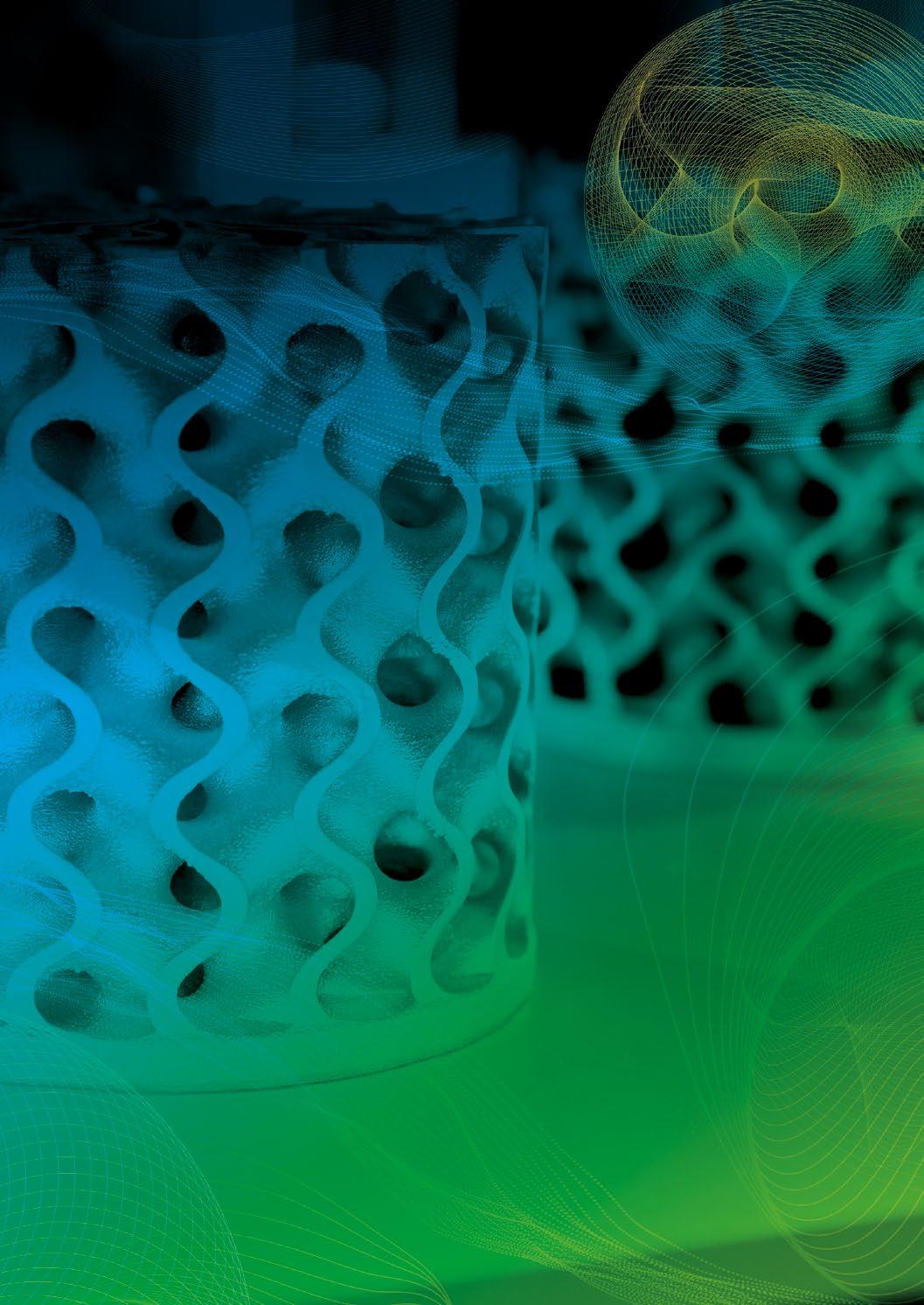
part of the fAMily!
the impossible possible!
Messe Frankfurt Group #formnext
Simulating sintering furnaces: A ‘check-and-act’ solution to optimse MIM and sinter-based AM production
The consistent high quality of sintered parts produced by Metal Injection Moulding, or AM processes such as Binder Jetting, can only be achieved with stable manufacturing conditions. Inhomogeneous and transient temperatures in sintering furnaces are one area where variability can be difficult to manage. This article outlines how simulation can lead to an optimal set up for the sintering process – or at least a best compromise – via the assessment of many possible process variations. Dr Götz Hartmann and Dr Wilfried Schäfer, MAGMA GmbH, and Dr Jesper Thorborg, Technical University of Denmark, share the results of recent research.
When developing and producing components, relatively optimum designs or manufacturing conditions must be found, especially against the backdrop of price pressure and quality requirements. We say “relatively” because an absolute optimum in these areas has always been a utopian dream. This is due to restrictions on the time and resources that have to be invested in the continuous improvement processes of component development and production.
‘Trial and error’ is the most widespread approach in engineering, regardless of whether one proceeds with parallel variants or sequentially. Trials in sufficient numbers are always time-consuming and costly and so the number, i.e. the richness of variants, is usually low. Of course, you can learn a lot from errors, but they are also expensive and, therefore, undesirable; the effort generated is often shamefully booked under ‘overhead costs’.
Over the past forty years, simulation technologies have developed in almost all technical areas, taking over a large part of the tasks of trial and error. Experiments can be run in
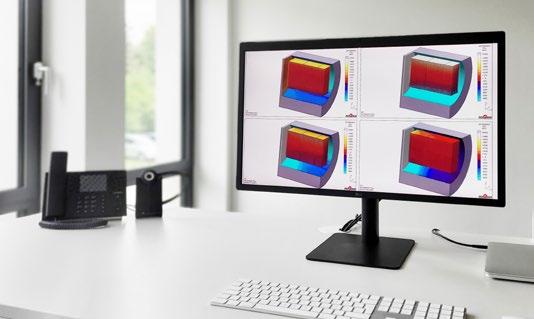
virtual test rooms and, due to the low cost of simulating a design or manufacturing variant, one can afford to make mistakes. Simulation becomes particularly efficient when many variants are calculated in virtual Design of Experiments (DOE) and evaluated more or less automatically and according to statistical aspects.
No other method can test or evaluate more variants of manufacturing processes and design variants of a component at the low-cost and speed of virtual DOE. This provides both the designer of a component and the manufacturing engineer with the best conceivable basis for fast, qualified decisions.
Fig. 1 Over the past forty years, simulation technologies have developed in almost all technical areas, taking over a large part of the tasks of trial and error. They become particularly efficient when many variants are calculated in virtual Design of Experiments (DOE) and evaluated more or less automatically and according to statistical aspects (Courtesy MAGMA GmbH)
71 SUMMER 2023 PIM INTERNATIONAL VOL. 17 NO. 2 © 2023 INOVAR COMMUNICATIONS LTD | contents | news | events | advertisers | website | newsletter | GETPDF
Furnace simulation
Potentials of the virtual assessment of sintering furnaces
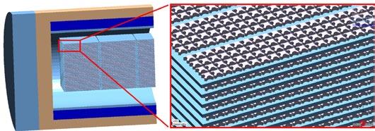
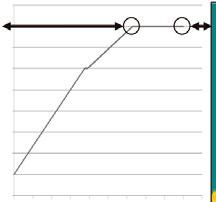
Consistently high-quality sintered parts can only be achieved with stable manufacturing processes under controlled conditions, starting with shaping (pressing, MIM, or processes such as Binder Jetting) and ending with sintering. The modelling of the sintering processes has long been the subject of numerous R&D projects. However, most of the models developed have not found any real application in the production environment of sintered parts; at best, they might find applications in production preparation. One reason for this low technology transfer from science to the real production environment could be that, in industrial sintering
processes, the temperatures of individual sintered parts change over time and vary depending on their position in the furnace. This means that each sintered part is exposed to an individual transient temperature environment during the sintering process.
A fast and efficient modelling approach developed recently [1] has now been integrated into standard heat treatment software for steel castings [2]. This paper reports on possible applications of this model at sintering furnace scale. This furnace model is able to predict the transient local temperatures of individual sintered parts at different positions in the furnace. For this purpose, the temperature- and time-dependent thermal conductivities of the parts are required as input for a further increase in accuracy and relevance, a
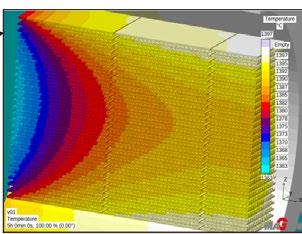
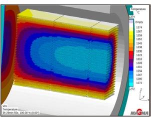
point that will be covered in detail.
The model for calculating the transient and inhomogeneous temperatures in sintering furnaces is used to assess a given sintering process. Accurate knowledge of the temperature-time histories for each individual location in the furnace and within the sintered parts, combined with the knowledge about the heat flows throughout the furnace, enables accurate prediction of potential problems during sintering.
However, the greatest benefit is derived from the application of the computational models when an optimal set up for the sintering process, or the best compromise, can be found via the assessment of many possible process variations. This topic will also be considered here – with different variations of batch furnace investigated – with the aim of achieving a homogeneous furnace temperature.
The transient and inhomogeneous conditions in sintering furnaces naturally have consequences for the sintered parts. In particular, temperature gradients within the sintered parts are the cause of various problems, whereby these become more relevant as the dimensions of the sintered parts increase. The consequences of inhomogeneous binder degradation caused by inhomogeneous heat input into the green part will also be discussed.
72 PIM INTERNATIONAL SUMMER 2023 © 2023 INOVAR COMMUNICATIONS LTD VOL. 17 NO. 2 | contents | news | events | advertisers | website | newsletter |
0h 1h 2h 3h 4h 5h Furnace simulation
Fig. 3 Temperatures of the sintered parts when the furnace temperature has just reached 1,400°C (left) and at the end of the holding time (right). The scales range from the lowest to the highest temperatures observed (Courtesy MAGMA GmbH)
Fig. 2 The thermally relevant components of the furnace (insulations, susceptor, heating elements, left) and of the rack with the sintered parts (tungsten plates, sintered parts, right) required for modelling are taken from CAD. The calculation mesh has a local resolution of 0.7 mm here (Courtesy MAGMA GmbH)
From furnace temperatures to the temperatures of individual sintered parts
It has already been observed that the temperatures of individual sintered parts at the beginning of the sintering phase differ by more than 30°C, depending on their position in the rack [1]. At the same time, the parts in the middle of the stack reach the desired sintering temperature more than 20 minutes later than the parts near the furnace heating. This proves that even a holding of the furnace temperatures during sintering leads to transient, nonuniform temperature environments for each sintered part.
The example presented here involves a sintering process in which around 18,500 carbide parts with dimensions in the cm range are sintered in a furnace under vacuum. For the calculation model, the thermally relevant areas are taken from CAD and meshed (Fig. 2).
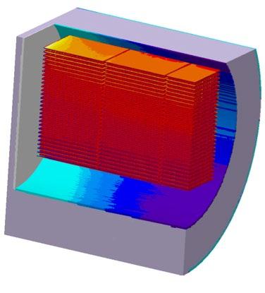
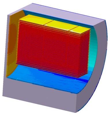
In the example shown, the target temperature of 1,400°C should be reached everywhere in the furnace after 3½ hours and then held at uniform, steady-state temperatures in the furnace for another 1½ hours. However, the calculation shows a different picture: the temperature distribution between the sintered
parts is clearly inhomogeneous: when the furnace temperature had just reached 1,400°C, the temperature differences were up to 100°C and, at the end of the holding time after a total of 5 hours, the temperature differences were still up to 34°C (Fig. 3). In this example, the radiant heat source is at 1,400°C and, due to vacuum sintering and the fact that the sintered parts are thermally decoupled from the tungsten plates by insulating alumina mats, no further types of heat transfer need to be considered.
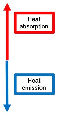
In order to understand exactly what leads to the obviously inhomogeneous and transient temperature distribution in the furnace, it is useful to investigate the heat flows in the furnace. In the case of vacuum
sintering, the determining variable is the heat radiation between all areas of the furnace, the rack and the sintered parts, as well as the heat conduction within all components represented in the model. The calculations show that, at the beginning of heating, the sintered parts facing the susceptor are exposed to a high heat flux of up to 3,500 W/m 2, while the sintered parts placed in the centre of the furnace receive almost no heat. The heat is emitted from the susceptor and absorbed by furnace walls, the inside of the furnace door and, of course, the rack and the sintered parts. The question of emission or absorption arises from temperature differences of the surfaces, between which radiant energy is exchanged.
73 SUMMER 2023 PIM INTERNATIONAL VOL. 17 NO. 2 © 2023 INOVAR COMMUNICATIONS LTD | contents | news | events | advertisers | website | newsletter | GETPDF
Fig. 4 The heat flux density here characterises the exchange of radiant energy. On the left, at the beginning of heating after 25 min. On the right, towards the end of the holding phase. The value of the heat flux density results from the temperature differences of all ‘face-to-face’ surfaces, as well as their emission and absorption coefficients (Courtesy MAGMA GmbH)
Heat absorption Net Radiation Flux W/m 2 Heat emission Empty +4000 +3429 +2857 +2286 +1714 +1143 +571 +0 -571 -1143 -1714 -2286 -2857 -3429 -4000 Furnace simulation
“In order to understand exactly what leads to the obviously inhomogeneous and transient temperature distribution in the furnace, it is useful to investigate the heat flows in the furnace.”
In the holding phase, considerable heat is still exchanged, which is due to the permanently-existing temperature gradients in the furnace. Conversely, this means that if a heat flow is displayed in the calculation, temperature differences prevail and the temperatures in the furnace are uneven (Fig. 4). It is both interesting and easy to see how much heat the unheated furnace door absorbs during the entire sintering process.
For the simulations quoted above, the thermal conductivity of the green compact was set at 50% of the reference value for the thermal conductivity of the 100% dense material. The increasing values of the thermal conductivity due to the density increasing during sintering were considered by a linear approach from 40 to 100% during the time from onset to complete sintering.
Temperature- and timedependent thermal conductivities of sintered parts: the link between calculations on powderscale and furnace-scale
The work described below was carried out for a stainless-steel alloy (316L) and was aimed at developing a method for determining the thermal conductivity of sintered parts during sintering [3]. The motivation arises from the necessary assumption that the material of the sintered parts is homogeneous throughout the complete sintering process for furnace-scale simulations. It was mentioned above that the enmeshment of the simulation model allows a local resolution down to just below 1 mm, which is about
two orders of magnitude too coarse in relation to the powder-scale.
Looking at the microscopic structure of a green part, one finds gas atomised steel particles of almost spherical shape and a certain size distribution and spaces between the powder particles filled with inert or reaction gas or vacuum (Fig. 5).
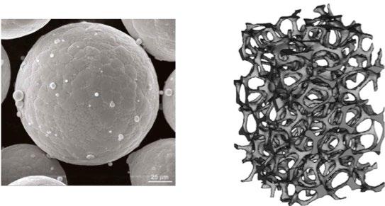
The heat transport through a green body is thus built up by two dominant mechanisms: To begin, there is the thermal conductivity within the steel spheres. Before the part starts to sinter, the heat transport between the steel spheres is clearly dominated by radiation. However, this strongly depends on the prevailing surface temperatures. Considering the extremely small contact area between the steel spheres, the heat transfer between the steel spheres can be neglected at this point.
The following approach to modelling the thermal conductivity of a sintered part before and during powder-scale sintering is based on this situation.
The components that make up a loaded sintering furnace, on the one hand, and a loaded vacuum heat treatment furnace, on the other, are basically the same: steel parts and vacuum. Verified numerical heat transfer models have recently been developed for the vacuum heat treatment of steel parts [2], which should be a useful basis for calculating the thermal conductivity of sintering probes before and during sintering.
The following approach is proposed for such a ‘virtual determination’: a standard virtual bar specimen was designed in CAD, consisting of steel spheres of one fraction and vacuum in the interstices. Varying the diameters of the spheres allows the variation of a steel/vacuum ratio between 57% (where the steel spheres are just touching) and 100% (no more vacuum volume). The varying steel/ vacuum ratio corresponds to a sample during sintering, where the density ranges from about 57% for the green part to 100% for the dense part.
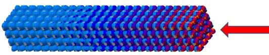
74 PIM INTERNATIONAL SUMMER 2023 © 2023 INOVAR COMMUNICATIONS LTD VOL. 17 NO. 2 | contents | news | events | advertisers | website | newsletter |
Fig. 5 A green compact in a vacuum sintering process consists of nearly spherical alloy particles and vacuum (Courtesy MAGMA GmbH)
6,000 4,000 2,000 0 -1,000 Radiation Heat Flux (W/m2) Furnace simulation
Fig. 6 Radiant heat flux along a virtual sintering sample. The radiant heat source is indicated by the red arrow (Courtesy MAGMA GmbH)
In the example shown in Fig. 6, one end of a 57% dense virtual sintered sample was exposed to a 1,000°C radiant heat source and simulated using the verified heat transfer model for radiation in vacuum of Fainberg and Schäfer [2]. The heat is transferred in the longitudinal direction of the sample. It can be observed how the radiation first heats the side of the first particles facing the heat source. Then the heat is conducted through the particles, which in turn transfer heat by radiation to their colder neighbours in the shadow of the heat source.
The result is a transient temperature distribution in the virtual specimen (Fig. 7). This combined heat transport from thermal radiation in the interstices of the specimen and thermal conduction within the powder particles leads to a characteristic transient temperature distribution in the specimen.
Due to the complexity of the physical relationships considered in this microscale model, the calculation takes some time, but provides detailed answers to questions about the heat transfer in green parts.
For the simulation of macroscale transient 3D heat transfer in complete furnaces or at least in furnace segments, with hundreds to tens of thousands of sintered parts, this approach cannot be used without
enormous computing times, even on computer cluster. For this reason, an approach is needed that helps to move from the microscale analysis of heat transfer in detailed sintered samples (see above) to a macroscale analysis of sintered parts in a furnace.
It was proposed that the detailed geometric model of the discrete virtual sinter specimen, as shown in Fig. 6 and Fig. 7, should be replaced by a model with a continuum structure, but with temperature- and timedependent thermal conductivities, as obtained from the above-mentioned heat transfer simulations of the virtual sinter specimen.
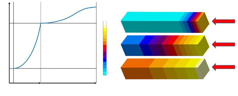
Two characteristic phases were defined: firstly, the heating phase, in which the thermal conductivity of the sample is determined by the temperature-dependent effects of heat conduction through the steel particles and radiation between them and secondly, the isothermal sintering phase, in which the thermal conductivity is determined by the same effects. The increasing amount of thermal conduction within the powder particles as they form an increasingly dense structure during sintering is considered (Fig. 8, left). The methodology used here is based on a virtual DOE, where
two characteristic phases: temperature-dependent before and timedependent during sintering.
Fig.
Virtual sample of homogeneous material with the same thermal conductivity as the microscale virtual sintered sample in Fig. 6, selected by virtual DOE (Courtesy MAGMA GmbH)
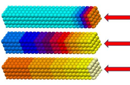
75 SUMMER 2023 PIM INTERNATIONAL VOL. 17 NO. 2 © 2023 INOVAR COMMUNICATIONS LTD | contents | news | events | advertisers | website | newsletter | GETPDF
Fig. 7 Radiant heat flux along a virtual sintering sample. The radiant heat source is indicated by the red arrow (Courtesy MAGMA GmbH)
8 Left: Typical thermal conductivity with
Right:
Thermal conductivity tsinter (min) Phase I Phase II 700 T(°C) 1200 0 180 100 100 500 500 1,000 1,000 Temperature °C Temperature °C Furnace simulation
the individual virtual specimens have different thermal conductivities. The respective individual simulations in the DOE use the same boundary conditions as the heat transfer simulation of the microscale simulations described above. In the automated evaluation of the results, the variant out of the DOE with the smallest deviation from the given transient temperature development of the detailed sintering specimen is searched for, as shown in Fig. 6 (and Fig. 8 right).
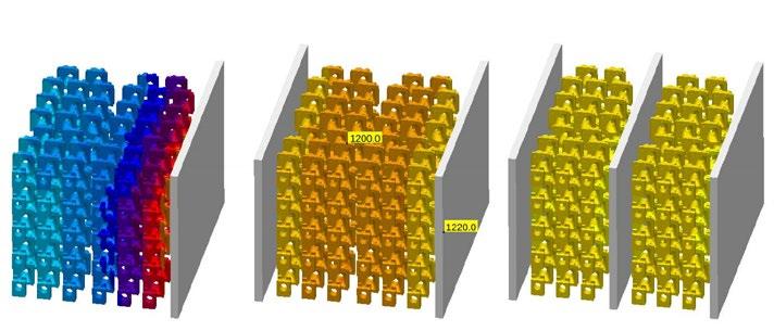
From the assessment of furnace temperatures to optimisation
As previously shown, heating and even holding phases in sintering furnaces are transient; at the same time, the temperature distribution in a sintering furnace is non-uniform at any time. When taking this into consideration, questions should be raised about process improvements to get closer to steady-state and uniform temperatures during sintering.
However, the development, testing and realisation of alternative heating concepts that could enable more uniform furnace temperatures is, of course, risky, time-consuming and
cost-intensive. One of the most interesting effects of virtual test methods, however, is that many technical approaches, even exotic ones, can be evaluated and documented with little effort and in a short time.
In batch sintering furnaces, the heating elements are, at least, located on the sides of the furnace chamber, sometimes additionally on the bottom and top. The reason for this is that, in this case, a rack carrying all the sintered parts can be loaded into the furnace in one step. What is somewhat neglected here is the above-mentioned problem of transient, non-uniform temperatures to which the sintered parts are exposed.
An admittedly exotic approach would be to install additional vertical heating plates parallel to the charging direction of the furnace. A virtual DOE was carried out for a virtual test and to document the possible effects of different heating element designs in a sintering furnace [3]. The variants have a different number of heating plates: the standard version: two plates at the sides of the furnace chamber, a version with one additional plate and a version with three additional heating plates (Fig. 9).
With one additional heating plate (Fig. 9 centre) the temperature distributions clearly become more even – and this proportionally more true
when more heating plates are added (Fig. 9 right.) If there are only heating plates at the sides of the furnace, the temperature difference between the parts near the heating plate and those in the centre of the furnace is about 35°C. This temperature difference is reduced to about 20°C with an additional heating plate in the centre of the furnace and to less than 6°C with a total of five heating plates.
The behaviour of green parts during thermal debinding
During thermal debinding of MIM and sinter-based AM green parts, defects may occur. These can be explained, for example, by uneven binder decomposition and the resulting uneven transient strains and stresses. The non-uniform binder degradation may in turn be due to non-uniform temperatures in the sintered part.
The decomposition of a binder can be described by an Arrhenius function, whereby the activation energy can be determined via thermogravimetry. In the example described below, a single sintered part from the calculation above was examined in more detail (see Fig. 9). A sintered part was selected from the centre of the rack, immediately next to the
76 PIM INTERNATIONAL SUMMER 2023 © 2023 INOVAR COMMUNICATIONS LTD VOL. 17 NO. 2 | contents | news | events | advertisers | website | newsletter |
Temperature °C 1220 1220 1220 Empty 1216 1211 1207 1203 1199 1194 1190 1186 1181 1177 1173 1169 1164 1160 Furnace simulation
Fig. 9 Temperatures of the sintered parts in a segment of a furnace at the end of the heating phase. The left-hand boundary of the calculation model is, in each case, the adiabatic furnace centre, the right-hand boundary is the heat radiator on the furnace side (Courtesy MAGMA GmbH)
radiant heat source. As a result, a green part in this position is exposed to a particular risk due to uneven, one-sided exposure to heat. The size of the sintered part is about 30 x 30 x 30 mm. The transient inhomogeneous temperature of the sintered part was

used as a boundary condition for the calculation of the binder degradation (Fig. 10). This binder degradation naturally leads to a characteristic elongation of the green part (Fig. 11), and this, in turn, leads to an equally characteristic contraction of
the green part (Fig. 12). To calculate this three-dimensional shrinkage, gravity-induced creep of the binder at temperatures below the decay was considered. A popular Cam-Clay model [e.g. 5] was utilised for the calculations.
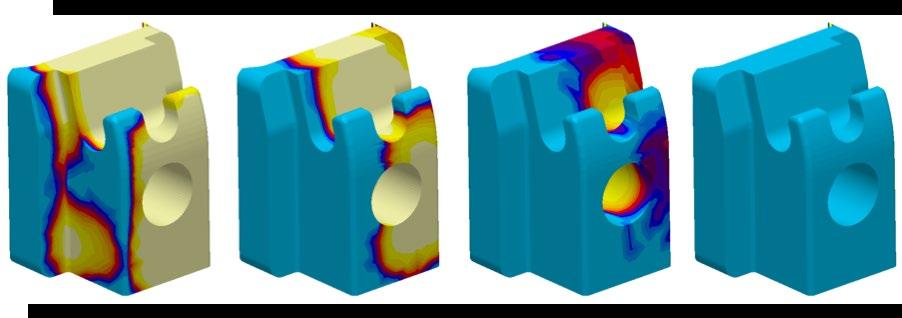
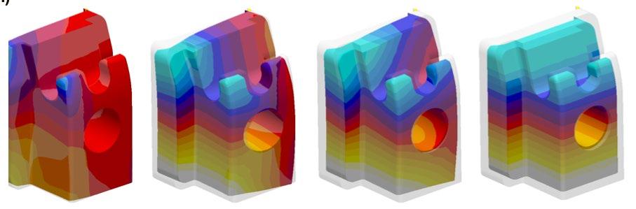
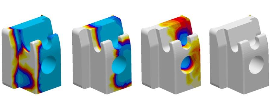
77 SUMMER 2023 PIM INTERNATIONAL VOL. 17 NO. 2 © 2023 INOVAR COMMUNICATIONS LTD | contents | news | events | advertisers | website | newsletter | GETPDF
Fig. 10 Inhomogeneous binder degradation during thermal debinding of a 316L - MIM part. The part is located in the centre of the rack and is directly irradiated by the heat source to the left of the sintered part. Local resolution in the calculation mesh is about 1 mm. The value 0 means “no decomposition”, the value 1 means “complete decomposition” of the binder (Courtesy MAGMA GmbH)
Fig. 11 Transient, local strain of the green compact during binder degradation (see Fig. 9) (Courtesy MAGMA GmbH)
Fig. 12 Transient, local contraction considering creep under gravity and free sliding on the substrate (Courtesy MAGMA GmbH)
Degradation 1.00 0.75 0.50 0.25 0.00 Strain (%) Contraction (mm) 0.0 +1.0 +0.5 -0.5 -1.0 0 -2.5 -5.0 -7.5 -10.0 Furnace simulation
Concluding remarks
In this article, some examples are shown where the thermal processes in sintering furnaces and sintered parts are very conclusive, which brings to question why these phenomena, which are known in principle, should be analysed and optimised with the aid of complex calculation models at all? The authors’ aim here was not to document concrete solutions for concrete problems, but to demonstrate the methodology of virtual assessment and virtual process optimisation and to point out their potential.
Authors
Dr.-Ing. Götz Hartmann and Dr. rer. nat. Wilfried Schäfer, MAGMA GmbH and Dr. Jesper Thorborg, Technical University of Denmark
MAGMA GmbH
Kackertstrasse 16-18, 52072 Aachen, Germany
G.Hartmann@magmasoft.de www.magmasoft.de
References
[1] G. Hartmann et al., “Fast and efficient optimization of the load temperature distribution in high temperature sinter furnaces”, Euro PM2017, Conference Proceedings, Milano, 2017.
[2] Fainberg J. and Schäfer W. 2015: “A fast and efficient adaptive parallel ray tracing based model for thermally coupled surface radiation in casting and heat treatment processes”, Proceedings of the 14 th International Conference on ‘’Modeling of Casting, Welding and Advanced Solidification Processes
(MCWASP XIV)’’, Hyogo, Japan 21 - 26 June, 2015.
[3] G. Hartmann et al., “Virtual sinter process optimization - a holistic multiscale approach”, Euro PM2018, Conference Proceedings, Bilbao, 2018.
[4] J. Thorborg, J. Klinkhammer and H-J. Gaspers: “Integrated modeling of deformations and stresses in the die casting and heat treatment process chain”, Giesserei-Special 01/2018, Giesserei-Verlag Düsseldorf 2018, p54ff.
[5] Roscoe K.H. and Burland J.B., 1968, On the generalised stressstrain behaviour of ‘wet’ clay, Eng. Plasticity, Cambridge Univ. Press, 535-609.
78 PIM INTERNATIONAL SUMMER 2023 © 2023 INOVAR COMMUNICATIONS LTD VOL. 17 NO. 2 | contents | news | events | advertisers | website | newsletter |
Furnace simulation
www.metal-am.com LATEST ISSUE OF DOWNLOAD THE MAGAZINE FOR FREE METAL AM COMMUNICATIONS INOVAR THE MAGAZINE FOR THE METAL ADDITIVE MANUFACTURING INDUSTRY


Formnext Forum – Austin is the first in a series of events to drive industrial 3D printing innovation and growth in the Americas. Hosted in one of the world’s most tech-forward manufacturing communities, Formnext Forum – Austin will connect leaders from across the industrial additive manufacturing supply chain. Start shaping your AM experience! Visit us at formnextforum.com August 28-30, 2023 / Austin, Texas Entertainment and Networking Events Hands-On Technical Tours Expert-Led Presentations and Demos Products and Equipment on Display Unique Only-in-Austin Experiences PRESENTED BY
Where Additive Manufacturing Innovation Takes Shape
Don’t panic! A hitchhiker’s guide to metal Fused Filament Fabrication (FFF)

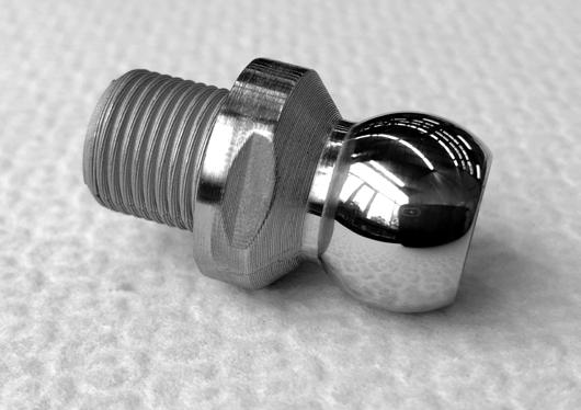
This is a story from what once looked like the edge of the metal Additive Manufacturing universe. A decade ago, the idea of a MIM feedstock-like filament for Fused Filament Fabrication (FFF) was the stuff of beer talk, but then things started to happen. Through a Facebook group called ‘FFF Metal 3D printing’ I discovered what felt like an underground community, driven by the seemingly impossible prospect of ‘printing metal’ on a shoestring budget. Amongst the dramatic images of failed builds and small piles of melted steel, posts by Sascha Lenze stood out. Here, he shares the story of L.B. Bohle Maschinen und Verfahren GmbH’s journey towards the Material Extrusion (MEX) of metal-containing filaments for industrial applications. Welcome to the new frontier!
More than four years ago, when I first became aware of metal Fused Filament Fabrication (FFF), it was Markforged and its Metal X system that brought it to my attention. Because our company’s focus was –and, for many reasons, still is – on 316L (1.4404) stainless steel, we already had some experience of metal Additive Manufacturing service providers, mostly using Laser Beam Powder Bed Fusion (PBF-LB). The low entry price of all-in-one solutions like that of Markforged, when compared to other metal AM processes, was immediately attractive to us.
We contacted Markforged to get more information about its product and, after some email conversations and phone calls regarding the prices for the particular part we intended to manufacture in the future, we met to explore the possibilities. To cut to the chase, at the end of that day we realised that such near-automated ‘all-in-one’ desktop metal Material Extrusion (MEX) packages were not the right choice for us. Because of our company’s background in mechanical handling and material
processing solutions, we place high demands on part specifications and performance. In our opinion, such systems struggle to deliver for the given material.
Subsequently, after almost no information regarding metal FFF could be found online except what
you can read about Metal Injection Moulding, and feeling a bit like Arthur Dent after his first teleport to the Vogon ship from Earth (rest in peace, Douglas Adams), we were lucky enough to discover a review on YouTube by Andreas Weiss of AMPro3D [1] showing the oppor -
81 SUMMER 2023 PIM INTERNATIONAL VOL. 17 NO. 2 © 2023 INOVAR COMMUNICATIONS LTD | contents | news | events | advertisers | website | newsletter | GETPDF
Fig. 1 Despite its home-brew nature, using metal containing filaments in a ‘standard’ polymer FFF machine can deliver outstanding results. Inset image shows a MicroSD card for scale (Courtesy Sascha Lenze)
A hitchhiker’s guide to metal FFF
tunities of sinter-based metal and ceramic FFF using filaments manufactured by Powder Technology and Additives (PT-A), a small company from Dresden, in the eastern part of Germany.
Still starry-eyed enough when it came to the complexity of the whole metal FFF procedure, I gave them a call, and after an hour (or so) of talking to Dr Karsten Pischang about his materials and the potential of the procedure, we were happy to order a 1 kg spool of 1.75 mm diameter 316L filament for some initial testing. With hindsight, one could mention that filaments of 2.85 mm diameter would probably have been a better choice because the highly-filled materials tend to break easily. However, our intention was to use the existing FFF machine we usually print polymers on (and, as an aside, this hypothesis did not play out anyway.) There were, of course, obstacles, but more on that later.
First results from metal filament in an ‘everyday’ printer
One of the first advantages that probably catches everyone’s eye when it comes to metal FFF is the opportunity to use an existing everyday polymer printer, which I suspect is at hand in pretty much every modern engineering or design business these days. In our case, it was a Sparkcube, a generic CoreXY DIY kit by Sparklabs, which had already been around in the workshop for a few years (Fig. 2). It is made from printed plastic parts, 2020 aluminium extrusions and (mostly) open-source hardware and electronics. All of the components – if not bought as a kit – could be easily self-sourced at the ‘usual suspects.’
With many years of experience building such machines from scratch, my colleague Manfred Groth and I chose it to give us the most freedom when it came to modifications for the specific demands of a process or application. The machine was equipped with a single printhead,
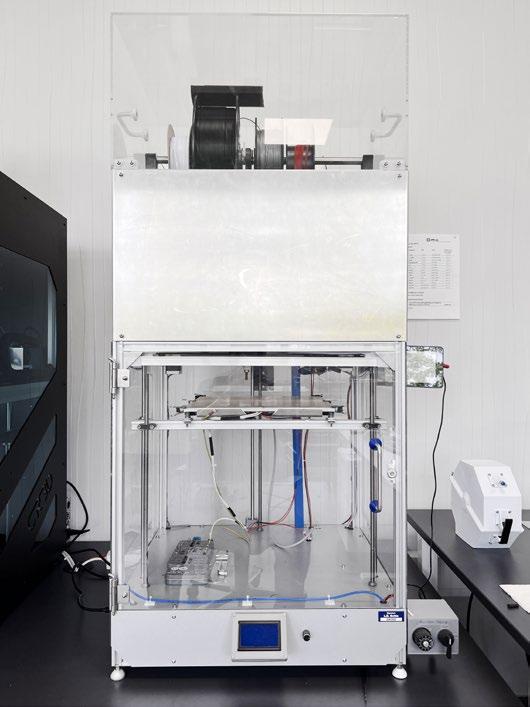
82 PIM INTERNATIONAL SUMMER 2023 © 2023 INOVAR COMMUNICATIONS LTD VOL. 17 NO. 2 | contents | news | events | advertisers | website | newsletter |
Fig. 2 The Sparkcube polymer printer, a generic CoreXY DIY kit from Sparklabs, was used for initial trials of metal filament (Courtesy Sascha Lenze)
A hitchhiker’s guide to metal FFF
“One of the first advantages that probably catches everyone’s eye when it comes to metal FFF is the opportunity to use an existing everyday polymer printer, which I suspect is at hand in pretty much every modern engineering or design business these days.”
a brass nozzle fitted ‘V6 All-Metal HotEnd’ manufactured by E3D in the UK, and a proprietary extruder by Sparklabs.
After having a hard time removing concrete-like filament residues from the hotend repeatedly, we replaced the extruder with a genuine Bondtech Dual-Drive BMG type (which was lying around at home anyway) and this reduced the risk of the extruder gears digging into the filament. Although there was no noticeable wear on the brass nozzle after many hours of builds, we switched to a hardened steel nozzle later on, primarily because brass nozzles are known to contain lead, and we were in fear of contamination issues on our stainless steel prints. That said, nickel-plated nozzles could probably be an option, depending on the desired material.
After the first few printing steps, another obstacle arose when we realised the filament was so brittle that it was broken easily by the printhead changing orientation with a reverse acceleration that was too high. Because the material always broke directly on top of the extruder, it was obvious that the guidance of the material to the extruder needed to be improved using a PTFE tube and, in the same step, move the filament spool on top of the printer over the centre of the print bed. There are some solutions on the market that add a second gantry for moving the spool synchronously to the printhead to overcome this issue, but fixing the tube directly to the spool holder gives pretty much the same result at almost no cost.
Learnings on adhesion and part removal
Bed adhesion has never been an issue when staying within the parameters recommended by the filament manufacturer, and neither was warping, unlike the other manufacturers’ materials. A well-levelled and slightly warmed (30°C) borosilicate glass bed printing at 40 mm/s printing speed with a hotend temper -
ature of approx. 130°C worked pretty well, but the prints often broke during removal due to the lack of flexibility of the glass. The fact they are approximately the strength of chocolate does not help much either.
For small parts, a razor blade works quite well to remove the part from the bed, but bigger and especially flat parts have always been a problem. We tried a broad variety of print plate materials and there were some that worked well for most geometries – PP foil, to name one –but the real game changer became apparent as we were playing around with some BASF Ultrafuse 316L filament, which we received together with BASF’s support layer material as a sample for testing.
BASF strongly recommends using Magigoo applied on the glass bed for an overall better bed adhesion and prevent the parts from lifting due to warping of the material. As a benefit, Magigoo is water-soluble, and when stored under water for a while the print self-separates from the glass. When printing a so-called ‘raft’ underneath the part, the process can be accelerated even further because the surface that comes in direct contact with the glass is way smaller with spaces at regular intervals.
The benchy test
A benchy is probably not what is typically produced as a trial object using an industrial Additive Manufacturing workflow, with material and machines typically being in a well-configured state, and there is probably no reason to print one except for the kids at home to have something to play with (Fig. 3). But those who are familiar with FFF would certainly agree that a material having what one may call ‘unknown characteristics’ can be a good starting point to get an overall impression of its behaviour in virtually any feasible geometry printed without supports.
Still, printing at low speeds with a given 400 μ m nozzle diameter and a 150 μ m layer height, the surface quality looked great, probably benefitting from the same optical effect as carbon or glass fibre-infused filaments, and the overhangs came out nicely. The only real drawback was that bridging [2] did not work well compared to what one would expect from polymers, which can probably be explained by the high specific weight of the metal-loaded material in combination with the low melting temperature of the binder system.
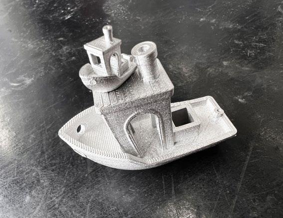
83 SUMMER 2023 PIM INTERNATIONAL VOL. 17 NO. 2 © 2023 INOVAR COMMUNICATIONS LTD | contents | news | events | advertisers | website | newsletter | GETPDF
A hitchhiker’s guide to metal FFF
Fig. 3 A benchy built as our trial object by metal FFF (Courtesy Sascha Lenze)
After switching from fan cooling to pressure air cooling by applying air by tube directly to the build area, things got better, but the results are nowhere near to anything we are used to from polymers. Supports can be helpful, but, as you can imagine, they can be difficult to remove depending on the geometry, and even harder when done postsintering because you are dealing with stainless steel. Solutions such as interface layer material, such as O 3 filament from BASF, can be useful as it enables the user to remove the metal supports easily by simply breaking the interface layer. A significantly better surface quality on steep overhangs is a good additional advantage. A printer equipped with two printheads is, of course, needed.
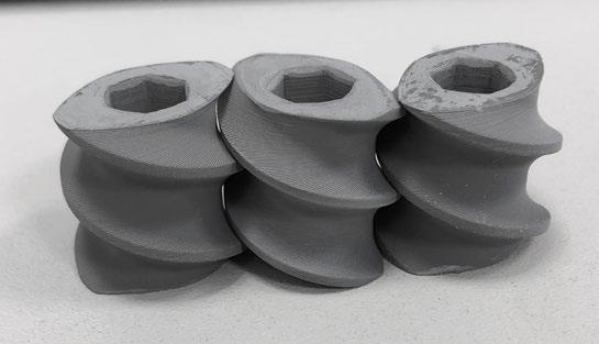
The challenge(s) of sintering
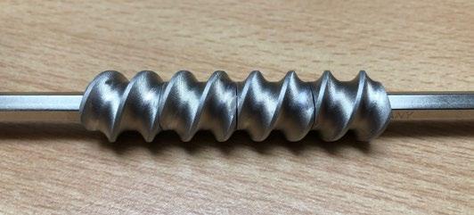
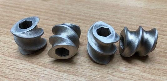
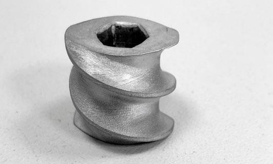
Manufacturing bottlenecks are something that we all have to come to terms with at some point. With some finished builds in our hands and an awareness of the maturity of the MIM process giving us some confidence that all would be okay, we did not expect to have quite so many difficulties finding a sintering services provider. Well, we learned the hard way and, to put it mildly, the delay was more like a cork in a bottle.
Along with having a hard time finding someone who would agree to sinter, the sintering furnaces often used for ‘toll-sintering’ are sized mostly for small batches of up to a thousand or more small MIM parts and, therefore, are way too big to process a batch of only a handful of parts for an acceptable cost. On the other hand, the option of putting our parts ‘somewhere in between’ within a larger sintering run is no solution either, because the sintering provider would go crazy on the diversity of different geometries of the parts you send them to sinter, which would take up too much space in the furnace.
84 PIM INTERNATIONAL SUMMER 2023 © 2023 INOVAR COMMUNICATIONS LTD VOL. 17 NO. 2 | contents | news | events | advertisers | website | newsletter |
A hitchhiker’s guide to metal FFF
Fig. 4 A granulator screw in 316L. Green parts are shown at the top, with as-sintered parts below. The bottom two images show as-sintered and assembled parts (Courtesy Sascha Lenze)
After searching for a while and feeling somewhat disillusioned, we came back to PT-A and were relieved that they agreed to help us out. We sent them our small collection of green parts (Fig. 4 shows a few). They did the debinding and sent the brown debound parts to Fraunhofer IFAM in Dresden to do the sintering, including some trial parts printed to one-shell wall thickness only (400 μ m) and as low as 10% infill, which was way off the recommended specifications one usually comes across when it comes to metal FFF.
Putting the results to the test
A little while later, we received the results in our mailbox and were surprised regarding the convincing quality of the parts. The surface was smooth and shiny and our first checks with the X-ray spectrometer, borrowed from our quality department, told us the material met the expected properties. Because most of the future builds we were planning were, at that point in time, products that would require some level of post-processing, we used the time to make some plans about how to proceed, including grinding, lathing, drilling and welding as well as polishing the sintered parts.
Grinding and lathing performed extremely well on the sintered parts. The longboard herringbone drive gear shown in Fig. 5, used in an electrical drive system, was designed by Manfred as a drop-in replacement for a polyamide part that broke from time to time due to the motor’s torque being too high when accelerating. For TIG-welding a printed part for conventional production (Fig. 6), we had some exciting first results followed by some setbacks on the next batch of sintered parts, which later on we could attribute to sintering atmosphere issues. Polishing of the parts worked fine as well (see Fig. 1); however, grinding too deeply into the material’s surface caused a ‘breakthrough’ of the first shell. This resulted in an area rich
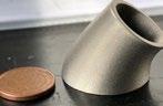
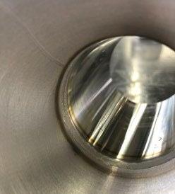
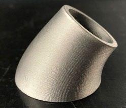
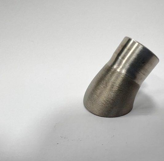
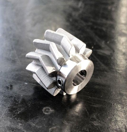
85 SUMMER 2023 PIM INTERNATIONAL VOL. 17 NO. 2 © 2023 INOVAR COMMUNICATIONS LTD | contents | news | events | advertisers | website | newsletter | GETPDF
A hitchhiker’s guide to metal FFF
Fig. 5 A 316L herringbone drive gear, post-processed (Courtesy Sascha Lenze)
Fig. 6 A printed 316L FFF part TIG-welded to a tube (Courtesy Sascha Lenze)
in small defects being exposed, which is an issue that is probably print density-related and needs to be addressed in the future.
Should we stay or should we go?
With long delays due to our persistent sintering availability issues, combined with useless or defective
parts returning from sintering and no real clue about the root cause of the issues, we started to ask ourselves whether we should better stop at this point and forget about sinterbased metal FFF or continue on the journey. For Manfred and me, there was little doubt about the answer –we consider the procedure well worth the effort that we had put in over the years. Fortunately, our management’s thinking was in harmony with ours,
so we started making plans for a dedicated in-house facility, including a printer, debinding unit and a sintering furnace.
With positive experiences regarding the materials as well as the support offered, we decided to continue using materials produced by PT-A. Because the binder system is dissolved by acetone, we chose a Loemi semi-automatic debinding system with integrated solvent recovery (Fig 7, right). We did not have much experience when it came to sintering furnaces, so we had to rely on the several positive reports that we received when discussing the procedure. We wanted to be able to sinter a wide range of materials, so maximum flexibility was our focus. In making our final decision, we chose a MUT furnace capable of operating under H, N and Ar (Fig. 7, left).
For a dedicated FFF machine, we had been in frequent contact with Christian Reil of CR3D, a small producer based in Bavaria. The I433 we finally ordered is an industrial-
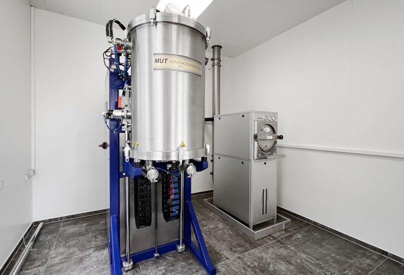
86 PIM INTERNATIONAL SUMMER 2023 © 2023 INOVAR COMMUNICATIONS LTD VOL. 17 NO. 2 | contents | news | events | advertisers | website | newsletter |
Fig. 7 A MUT sintering furnace and Loemi debinding unit (Courtesy Sascha Lenze)
A hitchhiker’s guide to metal FFF
“With long delays due to our still persistent sintering availability issues, combined with useless or defective parts returning from sintering and no real clue about the root cause of the issues, we started to ask ourselves whether we should better stop at this point and forget about sinter-based metal FFF.”
grade dual interchangeable extruder IDEX printing system based on, amongst others, Duet3D open-source hardware and leaves nothing to be desired when it comes to freedom of modification (Fig. 8).
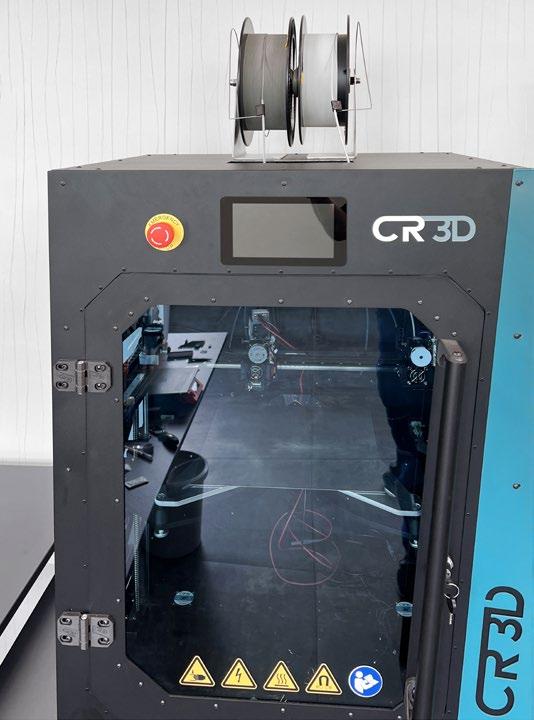
The printer arrived at the end of 2022 and since then we have had the opportunity to print a nice collection of 316L parts, often using Al 2O 3 interface layers (Fig. 9). As test parts we have produced 1 cm³ cubes (when sintered), which we plan to distribute evenly in the furnace chamber to evaluate temperature uniformity.

As a result of producing a lot of defective green parts when testing of the printer, we decided to purchase a cheap filament extrusion system, including a shredder built by Felfil, Italy, to experiment with filament recycling in order to save some money on the expensive filament.
Loemi delivered the debinding system at the beginning of the year and the company was on site for commissioning a few weeks later. The machine is built like a tank and, in addition to its original intended purpose, we created a ‘non-invasive’ acetone smoothing conversion kit for ABS and ASA parts that we sometimes need to smoothen, which works pretty well with the benefit that all the acetone is returned in the process.
A few weeks ago, after postponements due to problems with the delivery of electrical components, our MUT sintering furnace arrived on site. Sadly, because of some missing hardware relating to the gas supply, the commissioning is delayed. So, unfortunately, I cannot report much about our sintering journey yet.
The journey from here
For having come such a long way, it still feels like we have just started and there is a colourful bouquet of challenges waiting for us to overcome in the future. Because we have – as you may already have recognised – a less-than-scientific approach to the procedure, we started a partnership with Steffen
87 SUMMER 2023 PIM INTERNATIONAL VOL. 17 NO. 2 © 2023 INOVAR COMMUNICATIONS LTD | contents | news | events | advertisers | website | newsletter | GETPDF
Fig. 8 The CR3D I433 industrial-grade, dual interchangeable extruder IDEX FFF machine (Courtesy Sascha Lenze)
Fig. 9 Al2O3 interface layers on a part built using the CR3D I433 (Courtesy Sascha Lenze)
A hitchhiker’s guide to metal FFF
Florian at the FH Münster University of Applied Sciences to address green part density and other questions on the process. So, we will probably have some answers for those who have been asking for numbers at some point in the future.
The company that I work for, L.B. Bohle Maschinen und Verfahren GmbH, builds machines and develops solutions for customers in the pharmaceutical and metal AM industries all over the world. Our portfolio includes vacuum granulators, coaters, powder blenders and systems for continuous manufacturing. With parts of our machines coming into contact with active pharmaceutical ingredients or metal powders, we have a strong focus on the properties of AM parts in order to avoid contamination of the products. Material-specific properties need to be met, for example, when it comes to corrosion resistance, density and the surface quality of builds.
With a qualified FFF-based metal AM operation as our final goal, there is still much to do and there are many issues that need to be addressed on our way. So, let’s see how far we can get. If there are questions, please let me know. I am always open to a constructive debate regarding the procedure. With the whole process looking insanely complicated to operate, my only advice? Don’t panic!
Author
Sascha Lenze is a certified electrical technician, software developer PLC/HMI and metal FFF enthusiast with more than ten years’ background in FFF/FDM polymer AM as a hobbyist as well as a professional.
S.Lenze@lbbohle.de www.lbbohle.de
References
[1] www.youtube.com/ watch?v=5PNXb5dptr8
[2] Bridging is a FFF/FDM related term for the nozzle extruding a line of material between two parts of a geometry without supports, suspending the material in mid-air.
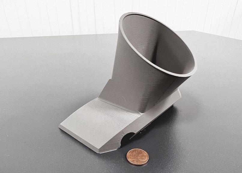
88 PIM INTERNATIONAL SUMMER 2023 © 2023 INOVAR COMMUNICATIONS LTD VOL. 17 NO. 2 | contents | news | events | advertisers | website | newsletter |
Fig. 10 One of the more complex parts now being produced (Courtesy Sascha Lenze)
A hitchhiker’s guide to metal FFF


https://www.pm-review.com/ subscribe-pm-review-e-newsletter/ COMMUNICATIONS INOVAR TO OUR WEEKLY E-NEWSLETTER SUBSCRIBE Subscribe to the Powder Metallurgy Review e-newsletter, sent weekly to key PM professionals and end-users worldwide, to make sure you benefit from timely access to the latest industry news and technology trends. E-newsletter subscribers also benefit from a free digital subscription to Powder Metallurgy Review magazine. www.pm-review.com POWDER METALLURGY REVIEW


MIM2023: Industry insights from the International Conference on Injection Moulding of Metals, Ceramics and Carbides
The 2023 International Conference on Injection Moulding of Metals, Ceramics and Carbides (MIM2023), organised by the Metal Powder Industries Federation (MPIF)’s Metal Injection Molding Association (MIMA), was held in Costa Mesa, California, USA, from February 27 to March 1, 2023. As well as being the annual meeting point of the US MIM community, the event attracts an international audience and has broadened in scope to include sinter-based Additive Manufacturing processes. Dr Animesh Bose reviews some highlights from the MIM2023 technical programme.
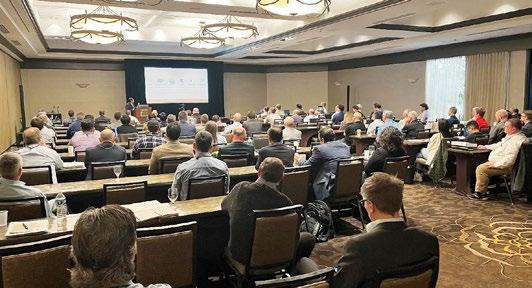
The objective of MIM2023 was to survey the advancements in the area of injection moulding of metals, ceramics and carbides and support the efforts of technology transfer across different areas of Metal Injection Moulding (MIM). It also looked to focus on new developments that contribute to the growth of MIM, and keep the community appraised and updated about other technologies, primarily sinter-based Additive Manufacturing, that could be complementary, but also pose a threat to MIM in some areas.
Although MIM2023 was organised as a hybrid event, including both online and in-person presentations, the in-person presentations significantly outnumbered the virtual ones. This was an extremely good sign for the industry, which is rebounding back to its pre-COVID days with attendance at the conference climbing to 138 and participation from 11 countries. International participation was still slightly weaker than expected, but is anticipated to bounce back next year.
In addition to the main technical sessions, the wider event
also featured the long-established one-day PIM tutorial, presented for many years by Prof Randall German and now by Matt Bulger, former president of the MPIF’s Metal Injection Molding Association (MIMA). MIMA standards committee, board of directors and members meetings also took place, as well as short commercial process and product innovation presentations and a tabletop exhibition.
Megatrends in near-netshape manufacturing
MIM2023’s opening keynote was delivered by Diran Apelian, Distinguished Professor, Materials Science and Engineering, at the University of California, Irvine, USA. This opening keynote presentation was on an extremely thoughtprovoking topic entitled Megatrends
International Conference on Injection Moulding of Metals, Ceramics and Carbides (MIM2023), organised by the Metal Powder Industries Federation (MPIF)’s Metal Injection Molding Association (MIMA) (Courtesy Animesh Bose / MPIF)
91 SUMMER 2023 PIM INTERNATIONAL VOL. 17 NO. 2 © 2023 INOVAR COMMUNICATIONS LTD | contents | news | events | advertisers | website | newsletter | GETPDF
Fig. 1 Delegates at the 2023
MIM2023 conference report
NINE
TECHNOLOGIES ARE RESHAPING PRODUCTION
Advanced robots
Additive Manufacturing
Augmented reality
Simulation
Horizontal and vertical system integration
The Industrial Internet of Things
in Near-Net-Shape Manufacturing. After his initial introduction, Apelian showed a slide stating ‘CHANGE: It is the Universal Constant’ which set the tone for the remainder of his presentation. The presentation was divided into four broad segments: digitisation/industry 4.2 TM/data science; sustainability, including resource recovery and decarbonistion; process innovations; and talentism (not capitalism nor socialism).
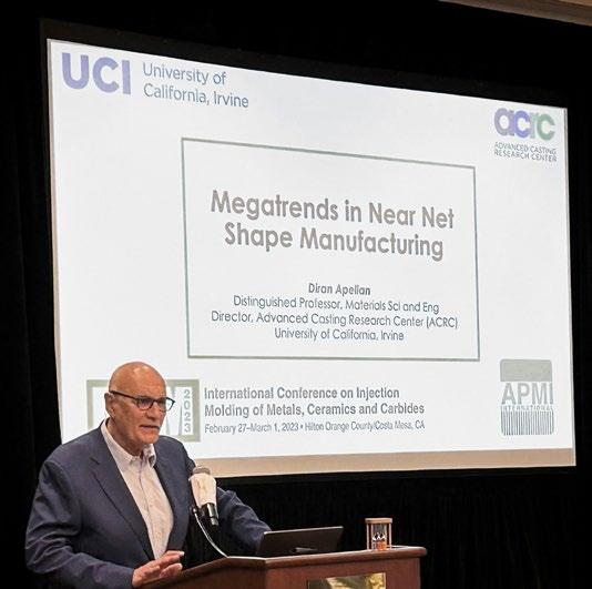
The presentation touched on the nine technologies that are reshaping production (Fig. 3). According to Prof Apelian, Industry 4.0 was going to consist of automation, connection, cloud computing, IOT, big data and system integration. Automation and Artificial Intelligence (AI) are expected to play a key role in the transformation to Industry 4.0. To emphasise that point, the presentation provided an interesting statistic on the change in stock values of these companies, compared to the Dow Jones Industrial Average, between 2 January 2020 to 4 January 2021. The compiled data showed
• Autonomous, cooperating industrial robots, with integrated sensors and standardised interfaces
• 3D printers, used predominantly to make spare parts and prototypes
• Decentralised 3D printing facilities, which reduce transport distances and inventory
• Digital enhancement, which facilitates maintenance, logistics and SOPs
• Display devices, such as glasses
• Network simulation and optimisation, which use real-time data from intelligent systems
• Data integration within and across companies using standard data transfer protocol
• Fully integrated value chain (from supplier to customer) and organisation structure (from management to shop floor)
• A network of machines and products
• Multidirectional communication among networked objects
• The management of huge volumes of data in open systems
• Real-time communication for production systems
Cybersecurity
Cloud computing Big data and analytics
Source: BCG analysis

• The management of heightened security risks due to a high level of networking among intelligent machines, products and systems
• The comprehensive evaluation of available data (from CRM, ERP and SCM systems. for example, as well as from a MES and machines)
• Support for optimised real-time decision making
Note: SOP = standard operating procedure | CRM = customer relationship management | ERP = enterprise resource planning | SCM = supply chain management | MES = manufacturing execution system
92 PIM INTERNATIONAL SUMMER 2023 © 2023 INOVAR COMMUNICATIONS LTD VOL. 17 NO. 2 | contents | news | events | advertisers | website | newsletter | MIM2023 conference report
Fig. 2 Prof Diran Apelian, Distinguished Professor, Materials Science and Engineering, University of California, Irvine, delivering the opening keynote presentation (Courtesy Animesh Bose)
Fig. 3 Nine technologies that are reshaping production (Courtesy Prof Apelian)
that the Dow Jones had increased by 5%, but the majority of companies involved in automation and AI (ten different companies) had increased from 20 to 68% over the same period.

It was stated that, “AI and robotics will transform tasks rather than make humans obsolete. The impact of AI and robotics depends on how we adopt them.” Machine Learning (ML), which is a branch of AI where one constructs computer algorithms to mimic tasks commonly performed by humans, is expected to play a critical role in the industrial transformation. This statement has reportedly been supported by Microsoft’s Bill Gates who has stated that “a breakthrough in ML would be worth ten Microsofts.” Deep learning, which is a subset of ML, is creating large disruptions and has the potential to keep driving the AI boom. A schematic of the timeline of AI, ML and deep learning is shown in Fig. 4.
The drive for sustainability is directly connected to the growth in the world’s population, which jumped from 1.6 billion in 1900 to 6.1 billion in 2000 and 7.8 billion in 2020. This increase in population, along with the demands placed on the world’s material resources, has created the urgent need to focus on sustainability. The areas of materials and advanced manufacturing will have a direct impact on energy and climate change, food and water, housing (shelter), mobility (transportation, cyber mobility) and health.
For sustainable development, the key areas of focus need to be production waste, post-consumer waste and materials for clean energy. The area of processing innovations is also intimately tied with sustainability. Recycling and recovery of materials (especially rare earth materials used in batteries) is critical in process innovations.

An interesting area of process innovation is gigacasting in the automotive industry, leading to a simplification of vehicle structures. This innovation has the potential to reduce the number of automotive parts needed for a car body structure from 171 to two, and require
1600 fewer welds. To keep up with the demand for large casting sizes, the die cast machine size range has increased dramatically over time. Prof Apelian pointed out that LK, the global leader in hot chamber and cold chamber die casting machines, has increased the locking force of its hot chamber die cast machine cells from 2000 to 12,000 tonnes since 1970 (Fig. 5).
Another important area that is tied to process innovations is the issue of conformal cooling in casting dies and injection moulding machines. This requires
improved thermal management that allows shorter cycle times, improved mechanical properties, complicated geometry (thick and thin sections), uniform die/ tool temperature, and better temperature control. AM is playing a key role in this area by allowing for increased tool complexity with fewer components and reduced lead times. Improvements in the performance of the tools are also dictated by new materials that can provide high thermal conductivity, high-temperature resistance and, thereby, result in extended tooling life.
93 SUMMER 2023 PIM INTERNATIONAL VOL. 17 NO. 2 © 2023 INOVAR COMMUNICATIONS LTD | contents | news | events | advertisers | website | newsletter | GETPDF MIM2023 conference report
Fig. 4 Schematic of the timeline of AI, ML and deep learning (Courtesy Prof Apelian)
Locking force in metric tons 1000 2000 3000 4000 5000 6000 7000 8000 9000 10,000 0 1960 1950s 1960s Early
intelligence
excitement ARTIFICIAL INTELLIGENCE MACHINE LEARNING DEEP LEARNING Machine learning begins to flourish Deep learning breakthroughs drive AI boom 1970s 1980s 1990s 2000s 2010s 1970 1980 1990 2000 2010 2020
Fig. 5 Die cast machine size range over time (Courtesy Prof Apelian)
artificial
stirs
THE FUTURE OF WORK AND THE WORKER INDUSTRY 4.2 TM

Prof Apelian acknowledged that talent is a scarce commodity and he quoted Klaus Schwab from the World Economic Forum, who stated that, “in the 4 th Industrial Revolution, it is all about talentism; not capitalism nor socialism.” Development and utilisation of the talent pool will be the key to the success of the 4 th Industrial Revolution. An illustration of the dream of Industry 4.2 TM and the future of work and the worker is shown in Fig. 6.
Sinter-based AM technologies
It is of interest to note that the MIM conferences organised by MPIF have, over the past five years, seen a steady increase in the number of AM presentations. This trend has been driven primarily by the similarities in some of the sinter-based AM processes and Metal Injection Moulding as well as the ongoing discussions about whether these
AM technologies are complementary or a threat to MIM. Recent years have also witnessed the proliferation of numerous sinter-based AM technologies.
It was felt that there was a need for a presentation discussing several relevant sinter-based AM technologies. This was covered in a presentation by Dr Animesh Bose (yours truly), formerly with Desktop Metal and now with Optimus Alloys, entitled “Review of Some SinterBased Metal AM Technologies.” The presentation illustrated the similarities and the differences between the majority of sinter-based AM processes and MIM, as shown in Fig. 7.
The differences between singlestep and multi-step processes, as outlined by ISO/ASTM 52900:2015, were discussed. It was pointed out that almost all the sinter-based AM processes were multi-step processes, where the parts are fabricated in two or more distinctly different operations. The first operation typically produces the basic geometry of the part and the subsequent step(s) results in the consolidation of the part to achieve the final properties (dependent on the desired material) of the part.
The presentation covered the broad technologies of Material
94 PIM INTERNATIONAL SUMMER 2023 © 2023 INOVAR COMMUNICATIONS LTD VOL. 17 NO. 2 | contents | news | events | advertisers | website | newsletter |
Fig. 6 An illustration of the future of work and the worker and Industry 4.2TM (Courtesy Prof Apelian)
Fig. 7 Schematic of MIM and sinter-based AM processes (Courtesy Animesh Bose)
Feedstock Feedstock Sinter-based AM MIM Build/print Moulding Debinding Debinding Consolidation Consolidation Powder, binder Powder, binder, mixing Tooling-pathing, print parameters Tooling, Machining, Controls Solvent, thermal Solvent, thermal Sintering, furnace Sintering, furnace MIM2023 conference report
Extrusion (MEX)-based processes, where the material is selectively dispensed through a nozzle or orifice. The material being extruded can become the final part itself, as in the case of pure polymer extrusion or hot extruding a metallic wire or polymer loaded with metal powder to form the final part.
Contrastingly, a MIM-type of feedstock, where metal powder is mixed with organic binders to form a feedstock, is extruded through a nozzle to build a geometric shape that is subsequently subjected to debinding and a consolidation step to result in the final part. This multi-step process has similarities with the MIM process, except for the geometric shaping, which is accomplished by a build process, or printing, instead of moulding.
Several processing techniques based on the MEX process, developed by different companies, were discussed and some applications were highlighted. Various commercial solutions based on the principle of MEX, including those using feedstock in the form of a filament or rod (Desktop Metal, MarkForged) and pellet-based extrusion processes (Pollen and AIM 3D), as well as extrusion of gel-based and pastebased feedstocks, were touched upon.
Another major process that was covered was Vat Photopolymerisation (VPP), which is based on photopolymerisation of a metal or ceramic containing slurry using a digital light engine. Some of the processes that have evolved based on this technology by different companies include Lithoz, Incus, Holo, Trio Labs and Tethon 3D.
Another interesting set of solutions that were covered include hybrid processes that combine additive and subtractive technologies to produce the final product. Some of the companies that are using these hybrid technologies include 3DEO, Mantle and Tritone (MoldJet). The presentation also discussed some of the other sinter-based AM processes, such as screen printing, Cold Metal Fusion and Nanoparticle Jetting.
A major part of the presentation
was based on Binder Jetting (BJT) technology, which has gained the best traction among all the sinterbased AM processes thanks to its promise of high-volume production capability at a low cost. The presentation pointed out that some of the technologies are complementary to MIM, supporting MIM companies in terms of quick tooling and even
rapid prototyping of actual metal parts. However, it was pointed out that some processes, such as BJT, can also pose competition to MIM due to their ability to fabricate parts with high productivity and without the requirement of any tooling.
Fig. 8 shows the packing of different parts in a Desktop Metal BJT process. The picture on the top shows
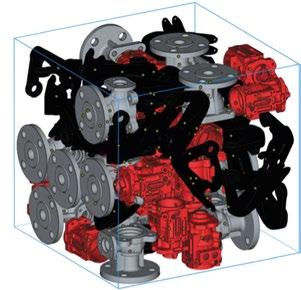
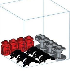
95 SUMMER 2023 PIM INTERNATIONAL VOL. 17 NO. 2 © 2023 INOVAR COMMUNICATIONS LTD | contents | news | events | advertisers | website | newsletter | GETPDF
Fig. 8 Two different arrangements for the layout of three different parts. The image on the top shows a single layer stacking of three different parts in a build box, whereas the picture on the bottom shows the optimised packing of the same three parts for the complete build box (Courtesy Desktop Metal)
MIM2023 conference report
“A major part of the presentation was based on Binder Jetting (BJT) technology, which has gained the best traction among all the sinter-based AM processes thanks to its promise of high-volume production capability at a low cost.”
a single-layer stacking of three different parts (housing, valve body and brackets) in a build box, whereas the picture on the bottom shows the optimised packing of the same three parts for the complete build box.
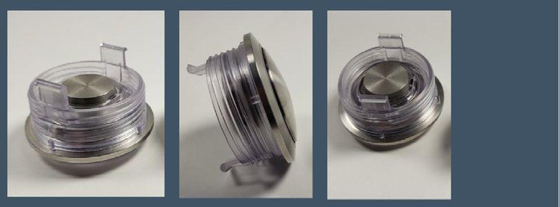
A MIM design challenge: 316L elevator button body
The current scenario, where AM can be complementary to MIM, was very well covered in the presentation by Gaetano Mariella of PTI Tech Inc., New Jersey, USA. In his presentation entitled ‘Utilizing Metal Injection Molding and AM Binder Jetting in the Production of a 316L Industrial Part’,
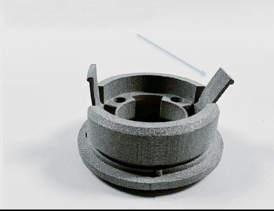
Gaetano detailed a case study that was initiated due to COVID-19. PTI was approached by a major elevator company to solve a problem with their current elevator button panels.
As can be imagined, these elevator button panels are high-touch areas by the public. Due to the COVID-19 pandemic, these button panels were subject to the widespread and increased use of chemical disinfectants to limit the spread of the virus. However, this increased use of various solvents and disinfectants was rapidly degrading the current legacy multi-part elevator button assemblies. Fig. 9 shows a picture of the current legacy overmoulded button assembly.
The design challenge faced by PTI was to consolidate the button assembly design and eliminate the polymer overmould. The designing and engineering of flexing retaining tabs and assembly threads in an all-MIM 316L button body design was challenging. Over and above that, the retaining tabs needed to be thin enough (~0.030”) to flex them by hand yet retain their shape without cracking.
However, the primary reason for incorporating AM was the tight timeline for project completion. PTI needed a rapid prototype technology that could manufacture productionrepresentative parts that could then dovetail into large-volume
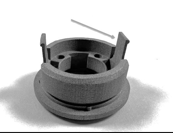
96 PIM INTERNATIONAL SUMMER 2023 © 2023 INOVAR COMMUNICATIONS LTD VOL. 17 NO. 2 | contents | news | events | advertisers | website | newsletter |
Fig. 9 The current legacy overmoulded button assembly (Courtesy Gaetano Mariella, PTI Tech Inc.)
Fig. 10 The results of button body tab flexing (Courtesy Gaetano Mariella, PTI Tech Inc.)
PC (polycarbonate) overmould of a machined stainless steel component.
Before flexing After flexing
MIM2023 conference report
Button cap is shown assembled with the button body
MIM production. Binder Jetting of 316L was used to solve the issues. Various iterations of the button body and the button cap were fabricated to test: a) various retaining tab cross sections; b) sintered dimensional control; c) machined surface finish; and d) final assembly design. For example, Fig. 10 shows the results of button body tab flexing, which was possible due to the thin tab made from 316L. All the tests, including the flexing, were completed without hard tooling and the finished prototype parts were successfully delivered to the customer before any tool steel for a mould was cut.
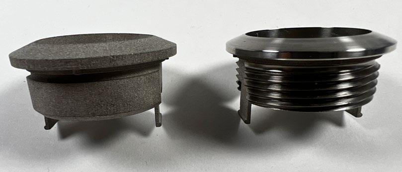
Fig. 11 shows the AM button body and the button cap in both the as-sintered and machined conditions. The rapid prototyping using the BJT process was the key to the success of the project. Once the design and properties were achieved (that satisfied the customer), attention was focused on MIM for high-volume production of the actual components. Multi-cavity hard MIM tooling was designed and manufactured by PTI using novel gating techniques, as well as novel techniques that were developed to release and eject the complex component geometry. Custom sintering setters were developed to ensure the
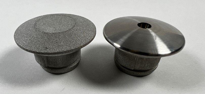
of extended thin retaining tabs while maintaining the flatness and concentricity of the button body.
The initial time and cost savings were significant when using the Binder Jetting process for prototyping. In addition, the process dovetailed very well with the MIM production process. The result was a cost-effective all-stainless steel industrial button assembly impervious to solvent and disinfectant chemicals while maintaining the same design as the mating electrical panel assembly.
This presentation highlighted a case where a sinter-based AM process was successfully used as the
97 SUMMER 2023 PIM INTERNATIONAL VOL. 17 NO. 2 © 2023 INOVAR COMMUNICATIONS LTD | contents | news | events | advertisers | website | newsletter | GETPDF
perpendicularity
MIM2023 conference report
Fig. 11 The BJT button body as-sintered (top left) and machined (top right). The BJT button cap as-sintered (bottom left) and machined (bottom right) (Courtesy Gaetano Mariella, PTI Tech Inc.)
perfect rapid prototyping method to establish the form, fit and function of the intended part, which was subsequently transitioned to high volume, near-net-shaped MIM components that were finally machined to yield the desired parts.
High-density powders by Uniformity Labs
Another interesting presentation from Uniformity Labs (UL), California, USA, was given by Dr Joseph Schramm, entitled ‘Performance of Highly
Uniform High Density Multimodal Stainless Steel Powders in Metal Injection Molding.’ This presentation highlighted the benefits of designed multimodal powders to attain higher solids loading in MIM feedstocks. The presentation highlighted the ability of UL powders to attain high relative densities, approaching that of the densest crystalline particle packings, while retaining their ability to flow without phase separation.
Fig. 12 shows a schematic of the densest natural crystalline packing of binary spheres and the UL maximally random jammed packing, both using
a powder size ratio of 5:1. It can be seen that the UL powder can attain a packing density that is almost the same as the densest natural crystalline packing.
Fig. 13 shows a schematic comparing a non-uniform particle distribution in moulded parts (left) to a 75% dense loading where the particles are spread uniformly and maintain the same high density (right). Earlier investigations by UL showed the benefits of its multimodal, highly packed powder in Binder Jetting and whether these benefits could be translated to MIM.

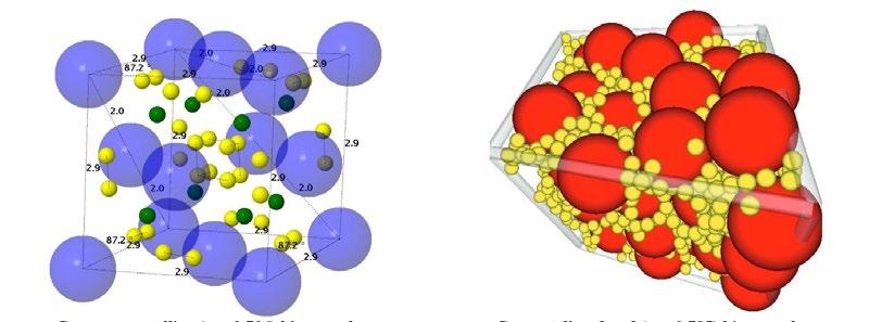
98 PIM INTERNATIONAL SUMMER 2023 © 2023 INOVAR COMMUNICATIONS LTD VOL. 17 NO. 2 | contents | news | events | advertisers | website | newsletter |
Fig. 12 Schematic of the densest natural crystalline packing of binary spheres (left) and the UL maximally random jammed packing, both using a powder size ratio of 5:1 (Courtesy Uniformity Labs)
Densest crystalline ( φ =0.796) binary sphere packing at 5:1 size ratio 1
Densest natural crystalline packing
UL maximally random jammed packing
Densest disordered ( φ =0.785) binary sphere packing at 5:1 size ratio 1
66% dense 66% dense 75% dense 75% dense Non-uniform particle distribution in moulded part
Fig. 13 Schematic of non-uniform particle distribution in moulded parts (left) and a 75% dense loading, where the particles are spread uniformly and maintain the same high density (right) (Courtesy Uniformity Labs)
part MIM2023 conference report
Particles spread densely and uniformly in
moulded
This work was done in collaboration with US MIM producer OptiMIM, based in Wilsonville, Oregon. UL 17-4 PH powders with a high tapped powder density (minimum –5.60 g/ cm 3; maximum –5.92 g/cm 3) were converted into feedstock with loadings ranging from 71 to 77 vol.% (less than 4% binder by mass). The feedstocks were moulded into tensile bars and it was determined that all the loadings were mouldable without requiring any equipment modification.
Fig. 14 shows the variation in the sintered densities of MIM bars with different feedstock loadings. It is interesting to note that the moulded bars achieve a very high sintered density as feedstock loading approaches the tapped density of the powder. This property then translates into lower shrinkage of the MIM bars at higher loadings, which is possible using the UL powder. Typically, lower shrinkage leads to lower distortion. Thus, UL powders of high tap densities can be beneficial to the MIM industry.
Solvents used in debinding
A topic that often does not get the coverage that it deserves is that of the solvents used in debinding. This topic was covered in detail by David A Ferguson of MicroCare, LLC. His presentation entitled ‘Solvent Debinding Series: Update: Comparing Overall Efficiency of Various Solvent Mixtures’ discussed the current trends in solvent use and showed lab experiments of different solvents. During the presentation, David pointed out the issues with some of the popular solvents, as outlined below:
• Heptane and hexane: flammable; require drying time due to their high boiling point
• Water: limited to water-soluble binders only
• Chlorinated solvents: toxicity/ environmental hazards
• Trichloroethylene: EPA deemed “unreasonable risk as a solvent in liquid degreaser/cleaner” (NPRM – Q1 2023)
Fig. 14 Results of the sintered density of MIM feedstocks moulded into bars with different feedstock loadings. It is interesting to note that the moulded bars achieve very high sintered density as feedstock loading approaches the tapped density of the powder (Courtesy Uniformity Labs)
Table 1 Solvent properties. Five representative solvents were chosen to address each type of fluid. The azeotropes are made up of blends of different solvents (azeotrope 85: 85% trans-dichloroethylene, 15% hydrofluoroether; azeotrope 92: 92% trans-dichloroethylene, 8% hydrofluorocarbon/hydrofluoro olefin blend) (Courtesy MicroCare, LLC)
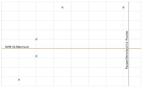
99 SUMMER 2023 PIM INTERNATIONAL VOL. 17 NO. 2 © 2023 INOVAR COMMUNICATIONS LTD | contents | news | events | advertisers | website | newsletter | GETPDF
“It is interesting to note that the moulded bars achieve a very high sintered density as feedstock loading approaches the tapped density of the powder. This property then translates into lower shrinkage of the MIM bars at higher loadings, which is possible using the UL powder.”
Blend ID Boiling point Flash point Surface tension (dyn/cm) Global warming potential (100 year) Perchloroethylene 121°C None 32 N/A n-Propyl Bromide 71°C None 26 16 Heptane 98°C 25°C 20 3 Azeotrope 85 48°C None 20 47 Azeotrope 92 47°C None 21 10
Sintered density, g/cm 3 Feedstock loading, vol.% 7.75 MPIF 35 Minimum Tapped Density of UL Powder 7.7 7.65 7.6 7.55 7.5 7.45 7.4 7.35 7.3 70% 71% 72% 73% 74% 75% 76% 77% 78% MIM2023 conference report
• Perchloroethylene: EPA deemed “unreasonable risk as a solvent for open-top batch vapor degreaser” (NPRM – Q1 2023)
• N-propyl bromide: toxicity/environmental hazard EPA deemed “unreasonable risk as a solvent for cleaning and degreasing in vapor degreaser” (NPRM – Q1 2023)
• Fluorinated mixtures: non-flammable, lower surface tension, faster drying time.
Laboratory experiments were carried out and five solvents were chosen. The solvent properties are outlined in Table 1 (Note: Tergo MCF is azeotrope 92 and Novec 73DE is azeotrope 85). A comparison of the amount of binder removed by different solvents is shown in Fig. 15. The time that it takes for the solvents to be removed at ambient temperature is also an important factor (Fig. 16). The overall debinding process efficiencies for different solvents are shown in Table 2. The presentation concluded with the following summary:
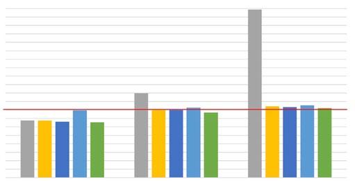
Heptane
This had the fastest debinding time with an average of 0.7 h/cm 3 Heptane also had the fastest overall processing time for debinding and heated drying with a requirement of 0.8 h/cm 3. Flammable liquid requires special equipment; not a significant toxicity hazard.
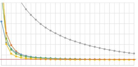
Azeotrope 92 (Tergo MCF)
This offered the fastest overall processing time for debinding and
100 PIM INTERNATIONAL SUMMER 2023 © 2023 INOVAR COMMUNICATIONS LTD VOL. 17 NO. 2 | contents | news | events | advertisers | website | newsletter |
Fig. 15 A comparison of the percentage of binder removed by different solvents (Courtesy MicroCare, LLC)
Blend ID Debinding time (min) Drying time at 21°C (min) Drying time at 50°C (min) Total processing time with ambient drying Total processing time with heated drying Perc 240 1440 60 28 h 5 h nPB 240 450 35 11.5 h 4.6 h Heptane 120 720 35 14 h 2.6 h Azeotrope 85 360 660 30 17 h 6.5 h Azeotrope 92 240 360 20 10 h 4.3 h
Fig. 16 Comparison of drying times for different solvents at 70°C (Courtesy MicroCare, LLC)
Table 2 Overall debinding process efficiency for different solvents (Courtesy MicroCare, LLC)
Drying time
Mass (g) Hours 2 hours 4 hours 6 hours Heptane change % Perc change % Perc nPB Heptane Novec 73DE Tergo MCF Novec 73DE change % nPB change % Tergo MCF change % 9 8 7 6 5 4 3 2 1 0 12.34 12.24 12.14 12.04 11.94 11.84 11.74 0 1 2 3 4 5 6 7 8 9 10 11 12 13 0.5 1.5 5.5 9.5 2.5 6.5 10.5 3.5 7.5 11.5 4.5 8.5 12.5 13.5 10 MIM2023 conference report
Debinding comparison of MIM parts in common solvents
of saturated MIM parts at 70°C
ambient drying with a requirement of 3.3 h/cm 3. This azeotrope also had the second fastest overall processing time for debinding with heated drying displaying an average rate of 1.4 h/cm 3. Non-flammable liquid can be used in open-top or vacuum equipment; not a significant toxicity hazard.
N-propyl bromide
This had similar results to Tergo MCF. Non-flammable liquid can be used in open-top or vacuum equipment. The toxicity concerns with this include carcinogenicity, as a result the solvent is facing regulatory action and phase-out.
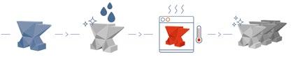

The Hammer Lab35 metal AM solution from Incus
One sinter-based AM process that has the potential to compete with MIM is Incus’s process based on Vat Photopolymerisation. A presentation of this process was given by Dr György Harakály of Incus, Austria, entitled Lithography-based Metal Manufacturing. His paper outlined the advantages of this process including the ability to produce complex green parts in a small- to medium-size range (1–200 g component mass), the highest resolution and surface aesthetics of metal AM processes, a wide range of materials with the possibility of processing non-flowable and non-weldable materials, a simple production process with easy preparation of printing jobs and quick exchange of materials, and safe working environment with no metal dust or high-power laser.
The presentation discussed the company’s lab scale machine that is currently on the market (Hammer Lab35) and mentioned their next production machine, known as Hammer Pro, which will have more than six times the build area compared to the lab version. This will enable the production of larger parts as well as parts in higher production volumes at a lower cost. Some of the details of the lab-size machine are shown in Table 3.
The as-sintered surface roughness of the process is around 2.17 μ m Ra, which can be reduced to 0.067 μ m with surface treatment. A schematic of the overall Incus lithographybased metal manufacturing process steps is shown in Fig. 17 and the detailed printing step is shown in Fig. 18. The process is capable of high-volume production and better surface finish compared to most AM processes.
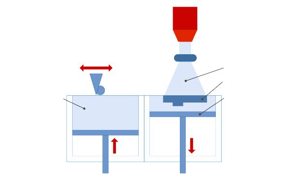
Final remarks
This review covers only a small section of the many interesting presentations that added tremendous value to the conference. It was difficult to pick and choose the papers to include in this report and many presentations that could not be covered for lack of space were also extremely insightful. The tabletop exhibition was mostly
101 SUMMER 2023 PIM INTERNATIONAL VOL. 17 NO. 2 © 2023 INOVAR COMMUNICATIONS LTD | contents | news | events | advertisers | website | newsletter | GETPDF
Building volume (X,Y,Z) 89.6 x 56 x 120 mm Lateral resolution 35 μ m Resolution Z 5-100 μ m Slice thickness 10-100 μ m Number of pixels (X,Y) 2560 x 1600 px Build speed Up to 250 slices/h Up to 100 cm 3/h
Table 3 The Hammer Lab35 printer from Incus: a desktop plug-and-produce network solution designed for material testing and small to mid-scale production (Courtesy Incus)
Fig. 17 Schematic of the process flow for the Incus process (Courtesy Incus)
Application Printed part Cleaning 3D imaging De-caking DLP engine Light Green part Building platform Blade Feedstock Material piston Building piston Lens Material mixing Post processing Final printed part LMM printing process
Fig. 18 Schematic details of the working of the lithography-based Incus AM machine (Courtesy Incus)
MIM2023 conference report
packed and the exchange of ideas and networking was ongoing.
The short ‘commercial’ presentations by various companies were also informative and of great value to people who may not have been familiar with the different products they offered. Even though MPIF organised this event in a hybrid format, there were only a handful of virtual presentations but attendance was reasonable for these digital talks.
Hopefully, future conferences will be able to do away with the hybrid format. Overall, it was heartening to see the enthusiasm and the excitement among the attendees as, hopefully, the world is looking at COVID-19 in the rear-view mirror.
 Author
Dr Animesh Bose President
Author
Dr Animesh Bose President
Optimus Alloys
Durham, North Carolina, USA abose@optimusalloys.com
Acknowledgments
I would like to acknowledge the support received from MPIF staff (James Adams and Bill Edwards) and the authors for their help with the figures used in this report.
102 PIM INTERNATIONAL SUMMER 2023 © 2023 INOVAR COMMUNICATIONS LTD VOL. 17 NO. 2 | contents | news | events | advertisers | website | newsletter |
Fig. 19 Top: James Adams, Executive Director/CEO, MPIF (right), with Prof Randall German. Middle: the reception hosted by Arburg USA. Lower: S K Tam, - Powder Matrix Forming Technologies LLC, at the MIM2023 table-top exhibit (Courtesy Animesh Bose / MPIF)
MIM2023 conference report
FROM OUR ARCHIVE
THE EVOLVING STORY OF METAL BINDER JETTING: THE PAIN AND THE PROMISE


Binder Jetting – at once the new kid on the block yet one of the industry’s earliest processes – holds the promise of taking metal Additive Manufacturing into the territory of true highvolume production. Yet progress towards this goal appears to be struggling, with machine sales lower than many hoped and two new ‘big players’ appearing to be holding back on full commercialisation.
In this report, Joseph Kowen considers the development of this industry to date, the obstacles facing its growth, and, of course, the recent announcement of two of Binder Jetting’s biggest rivals coming together in the most unexpected acquisition.

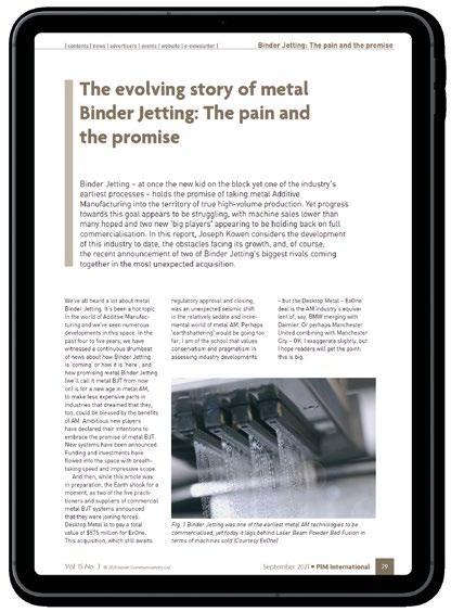
THE SEPTEMBER 2021
OF
INTERNATIONAL WWW.PIM-INTERNATIONAL.COM
FROM
ISSUE
PIM
READ NOW

Greening MIM: How Arburg is supporting energy and cost reductions in injection moulding facilities
Arburg GmbH + Co KG, Lossburg, Germany, a pioneer in the use of sustainable energy in its own operations, is now leveraging that expertise to support its customers in their mission to reduce energy consumption and improve the sustainability of injection moulding operations. Here, the company reports on its ‘Action Plan: Energy’, launched earlier this year, which has the specific goal of identifying and implementing a broad range of energy- and cost-saving opportunities.
Anyone who has been on a tour of Arburg’s Lossburg facility in Germany will know that energy efficiency has always been one of the company’s guiding principles. With recent price increases, the importance of energy has rapidly escalated throughout Europe and worldwide. This is, in part, why Arburg launched its ‘Action Plan: Energy’ in March this year, with a view to support its customers in maximising the energy efficiency of their injection moulding operations.
The plan is based on initial individual energy consultations as well as an energy survey which gathers data from a customer’s premises. The resulting analysis highlights many options for optimising energy requirements throughout the production process, thereby significantly reducing costs in injection moulding production.
Gerard Böhm, Managing Director Sales and Service at Arburg, stated, “The importance of energy costs increased at lightning speed in the injection moulding sector in 2022. We have responded to this with a professional action plan. The history of our
company and our current activities show that we are great at saving energy, both in terms of our products and our in-house production. We allow our customers worldwide to benefit fully from this knowledge. With our in-depth expertise, machine upgrades and digital services, we support injection moulding plants and make them strong and resilient with regard to energy efficiency.”
Arburg’s energy action plan
After an initial video conference, Arburg’s experts go to a customer’s premises, where they follow a fivestep plan (Fig. 2). The first step is to determine energy requirements and consumption in a real production environment. For example, potential ‘energy guzzlers’ can be revealed by measuring power and compressed air
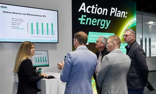
105 SUMMER 2023 PIM INTERNATIONAL VOL. 17 NO. 2 © 2023 INOVAR COMMUNICATIONS LTD | contents | news | events | advertisers | website | newsletter | GETPDF Arburg’s Action Plan: Energy
Fig. 1 Energy efficiency was an important theme of the Arburg Anniversary Days 2023 and the ‘Action Plan: Energy’ generated a high level of interest (Courtesy Arburg)
Action Plan Energy: 5-stage concept


leakages (Fig. 3). The measurement data are used for subsequent advice on process optimisation directly at the machine (Fig. 4). This is followed by new measurements to evaluate the success of these processes. In step 2, the machine fleet is classified, and individual retrofits are considered. Step 3 comprises of process and cycle time optimisations with the aim of increasing output and reducing specific energy requirements. In steps 4 and 5, the experts deal with the ‘dos and don’ts’ of moulds and peripheral equipment.
At the end of the action plan, there is a detailed consultation and a final discussion with the customer. The customer is given a list of measures with all of the information and specific recommendations on suitable retrofits and digital solutions, as well as the use of possible subsidies, dependent on the region. Arburg can also provide documented and traceable consumption measurements for new machines for businesses that require detailed energy data for certification. This service has three components:
Basic
A measurement of the energy requirement during the operating phase of the Arburg injection moulding machine and robotic system.
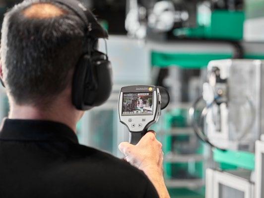
Extended
The energy requirement during the start-up and cooling phases, including peripheral devices, is determined in addition to the operating phase.
Complete
Additional measurements of water and compressed air consumption, flow rate and cooling capacity are taken.

How upgrades and retrofits can save energy
Existing Allrounder injection moulding machines of all sizes and series can be retrofitted with

106 PIM INTERNATIONAL SUMMER 2023 © 2023 INOVAR COMMUNICATIONS LTD VOL. 17 NO. 2 | contents | news | events | advertisers | website | newsletter | Arburg’s Action Plan: Energy
Productionenvironment Machine Prozess Werkzeug Peri‐pherie Kick-Off Finalisation: 1)Feedback discussion 2)Final report digitalisation Start: energymeasurement End: energymeasurement
Fig. 2 Arburg’s comprehensive energy advice follows a 5-step plan based on energy measurements in a real production environment at the customer’s premises (Courtesy Arburg)
Fig. 3 Measurements of power and compressed air leakages reveal energy guzzlers (Courtesy Arburg)
“At the end of the action plan, there is a detailed consultation and a final discussion with the customer. The customer is given a list of measures with all the information and specific recommendations on suitable retrofits and digital solutions...”
upgrades to optimise their energy usage. Depending on the application, fully insulating the cylinder may be worthwhile (Fig. 5) in order to ensure that process heat losses are minimised, as well as improving heating speed. With this measure, the energy requirement in relation to heating energy can be reduced by up to 40%, depending on the process.
Machines made in 2011 or earlier (with IE1 and older motors) can benefit from an upgrade to energyefficient air- and water-cooled IE3 motors. This can result in an energy saving of up to 10%, which means a return on investment (ROI) of only one and a half to two years, depending on the machine.
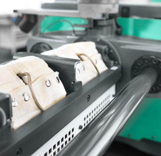
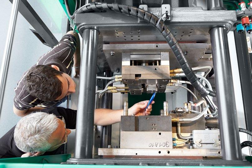
Newer Allrounders can be retrofitted with the Arburg Energy Saving system (AES) to reduce production costs. Assuming a cycle time of 50 seconds and 6,000 hours of production per year, a hydraulic Allrounder 270 S can save around €4,800 with electricity costs of €0.40 per kilowatt
107 SUMMER 2023 PIM INTERNATIONAL VOL. 17 NO. 2 © 2023 INOVAR COMMUNICATIONS LTD | contents | news | events | advertisers | website | newsletter | GETPDF Arburg’s Action Plan: Energy
Fig. 4 As part of the ‘Action Plan: Energy’, Arburg’s experts determine the energy requirements of injection moulding production at the customer’s premises. This measurement data forms the basis for intensive consultation and an individual list of measures (Courtesy Arburg)
Fig. 5 Energy-optimised by retrofit: full insulation of the cylinder can reduce the energy requirement by up to 40% (Courtesy Arburg)
EnergyAssist: lower power consumption and power peaks
EnergyAssist: lower power consumption and power peaks
hour, for example. In general, the payback period for an investment of this kind depends on the energy costs, machine, and process.
The Gestica machine controller actively supports the operator, including when it comes to energy optimisation. The assistance function ‘aXw Control EnergyAssist’ brings together all the essential functions for the heating zones of the plasticising cylinder and the mould hot
runner, for example, and ensures that all heating zones are switched on and off in an optimised manner. This can reduce the energy requirement in the heating phase by up to 30% (Fig. 6).
Built for energy-efficiency: the new Allrounder 470 H
Arburg has shown what an energyoptimised injection moulding machine
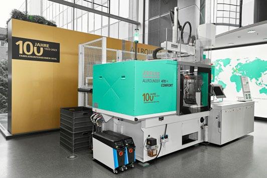
looks like with the Allrounder 470 H (Fig. 7). “When designing the hybrid Allrounder 470 H, we made significant advances to our tried-and-tested technology in order to optimise the energy footprint and reduce cycle times,” explained Guido Frohnhaus, Managing Director of Technology & Engineering at Arburg.
“There are many technical innovations in the new machine generation that are only available from Arburg”. These innovations include its new oil management system, flow splitting for simultaneous movements of hydraulic secondary axes, and the extended use of the Arburg servo hydraulic system. The new machine saves energy, conserves resources, is efficient in production, user-friendly, and reliable.
This is ultimately made possible thanks to the combination of the electric clamping unit and hydraulic injection unit. The electric drives reduce the energy requirement and thus the operating costs and carbon footprint, while the high-quality hydraulic injection unit lowers the purchase costs whilst being very robust.
A comparison of the hybrid Allrounder 470 H machine with similar capacity hydraulic machines results in figures that suggest a 50% smaller overall energy footprint,
108 PIM INTERNATIONAL SUMMER 2023 © 2023 INOVAR COMMUNICATIONS LTD VOL. 17 NO. 2 | contents | news | events | advertisers | website | newsletter | Arburg’s Action Plan: Energy
Fig. 7 The hybrid Allrounder 470 H milestone machine sets the stage for a new type of machine technology that is particularly good at saving energy and conserving resources, and is efficient in production, user-friendly and reliable (Courtesy Arburg)
0 2 4 6 8 10 12 14 16 18 20 1256511766102112761531178620412296 0 2 4 6 8 10 12 14 16 18 20 1256511766102112761531178620412296 simultaneous heating Heating up with EnergyAssist Temperature control units Hot runner Cylinder module [kW] [s] [kW] [s]
0 2 4 6 8 10 12 14 16 18 20 1256511766102112761531178620412296 0 2 4 6 8 10 12 14 16 18 20 1256511766102112761531178620412296 simultaneous heating Heating up with EnergyAssist Temperature control units Hot runner Cylinder module [kW] [s] [kW] [s]
Fig. 6 The ‘aXw Control EnergyAssist’ function in the Gestica controller reduces power consumption and power peaks during heat-up. The result is a reduction in energy requirements of up to 30% (Courtesy Arburg)
a CO 2 reduction of up to 12,000 kg per year, a 35% reduction in the oil required (preheated by waste heat), and 50-70% reduction in the cooling water required.
Accessing and visualising energy data
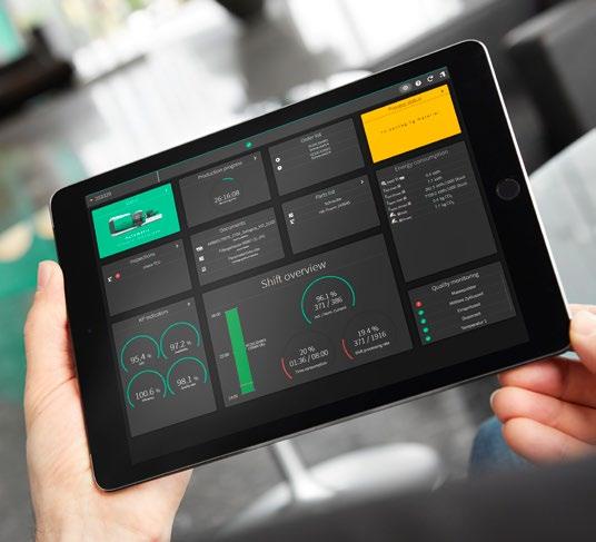
Access to the right data can help make production processes more energy efficient and create transparency. The arburgXworld customer portal plays an important role in this regards. A new feature within the MachineCenter app is that of energy labels in which each Allrounder is assigned to one of three energy efficiency classes. In addition, its carbon footprint is displayed from the creation phase to delivery to the customer.
Depending on the machine, the customer portal also provides tailored suggestions for energy optimisation, for example through retrofits. The new equipment comparison option helps users quickly and efficiently find the best Allrounder for their current injection moulding process during production planning. Another tried-and-tested tool for determining the most efficient solution is the Arburg cost effectiveness calculator, which uses important parameters to compare the various options and determine unit costs and the payback period, for example.
The host computer system, ALS, also makes a significant contribution to increasing the production and energy efficiency of machines and systems. Arburg’s proprietary manufacturing execution system (MES) allows users to digitally plan and control their entire parts production process and track all relevant information. Mobile ALS functions enable resource-saving paperless production and energy requirements can be visualised and evaluated via ALS (Fig. 8). In the information and machine terminal, the total energy requirement of the current job, the energy requirement per 15 minutes or the average output per 15 minutes can be displayed.
Conclusion
Energy consulting, as part of a professional action plan, forms an important new component of Arburg’s portfolio of services. Customers can benefit from this in a very tangible way, especially in times of scarce resources and high energy costs, with on-site energy measurements and in-depth advice identifying specific areas for action.
The subsequent implementation of individual measures in a manufacturing plant, adjustments to the machines, and the use of digital features and supplementary training courses opens up enormous potential that can significantly reduce energy requirements and, therefore, costs.
109 SUMMER 2023 PIM INTERNATIONAL VOL. 17 NO. 2 © 2023 INOVAR COMMUNICATIONS LTD | contents | news | events | advertisers | website | newsletter | GETPDF Arburg’s Action Plan: Energy
Contact Arburg GmbH + Co KG 72286 Lossburg Germany www.arburg.com Further information on Arburg’s ‘Action Plan: Energy’ can made by contacting energy@arburg.com.
Fig. 8 With the mobile ALS functions, users can always keep an eye on production, and its energy requirements can also be visualised and evaluated (Courtesy Arburg)
www.twitter.com/PIMMagazine

www.linkedin.com/company/ piminternationalmagazine/


As the usage patterns of PIM International magazine’s audience develop and change, we have expanded our social media activities, enabling us to connect with our global audience on multiple levels.

COMMUNICATIONS INOVAR


SOCIAL
OUR
MEDIA PRESENCE
www.facebook.com/PIMInternationalmag // SOCIAL MEDIA //
As the only magazine for MIM, CIM, and sinterbased AM, our LinkedIn, Twitter, and Facebook channels serve as indispensable sources for the latest industry news.
Advertisers’ index & buyer’s guide
PIM International is the only business-to-business publication dedicated to reporting on the technical and commercial advances in the MIM, CIM, and sinter-based Additive Manufacturing industries. Available in both digital and print formats, PIM International is the perfect platform to promote your company to a global audience.
Metal powders
Injection moulding machines
MIM, CIM & AM parts producers
Binders & feedstocks
Advertise with us...
Combining digital and print publishing for maximum exposure
Every issue of the magazine is distributed via multiple channels, including our website, e-newsletters and social media networks.
The print edition is distributed at numerous industry events worldwide as well as to a core subscriber base.
All past editions of PIM International magazine are freely accessible via our digital archive, adding extended exposure for your brand and products.
For more information contact:
111 SUMMER 2023 PIM INTERNATIONAL VOL. 17 NO. 2 © 2023 INOVAR COMMUNICATIONS LTD | contents | news | events | advertisers | website | newsletter | GETPDF Advanced Technology & Mat. Co., Ltd. 41 www.atmcn.com/english BluePower Casting Systems GmbH 39 www.bluepower-casting.com Epson Atmix Corporation 08 www.atmix.co.jp Höganäs AB 25 www.hoganas.com Jiangsu Tianyi Ultra-fine Metal Powder 55 www.cip-world.com | www.tycx.cn Jiangxi Yuean Advanced Mat. Co., Ltd. 49 www.yueanmetal.com JSJW New Material Co., Ltd. 57 www.jsjinwu.com Kymera International 33 www.kymerainternational.com LD Metal Powders 59 www.ldpowder.com Sandvik Additive Manufacturing 21 www.metalpowder.sandvik Tekna 11 www.tekna.com Ultra Fine Powder Technology 29 www.ultrafinepowder.com
Advertisers’ index & buyer’s guide Arburg GmbH & Co. KG OBC www.arburg.com WITTMANN Technology GmbH 27 www.wittmann-group.com
AMT Pte. Ltd. 18 www.amt-mat.com Indo-US MIM Tec Pvt Ltd 37 www.indo-mim.com KRAHN Ceramics GmbH 51 www.krahn-ceramics.com/en Visottica Industrie S.p.A. 52 www.visotticagroup.com
Jon Craxford, Advertising Sales
Tel: +44 207 1939 749 | jon@inovar-communications.com Advanced Metalworking Practices, LLC 17 www.ampmim.com INMATEC Technologies GmbH 34 www.inmatec-gmbh.com KRAHN Ceramics GmbH 51 www.krahn-ceramics.com/en PolyMIM GmbH 22 www.polymim.com Ryer Inc. IFC www.ryerinc.com Tosoh Europe BV 15 www.tosoheurope.com
Director
Alphabetical index
112 PIM INTERNATIONAL SUMMER 2023 © 2023 INOVAR COMMUNICATIONS LTD VOL. 17 NO. 2 | contents | news | events | advertisers | website | newsletter | 4 th Workshop on Sinter-based AM 113 Advanced Metalworking Practices, LLC 17 Advanced Technology & Materials Co., Ltd. 41 AMT Pte. Ltd. 18 Arburg GmbH & Co. KG OBC BluePower Casting Systems GmbH 39 Centorr Vacuum Industries, Inc 19 CM Furnaces Inc. 42 CREMER Thermoprozessanlagen GmbH 46 Desktop Metal, Inc. 04 Elnik Systems 06 Epson Atmix Corporation 08 Erowa AG 30 Euro PM2023 IBC Formnext 70 Formnext + PM South China 104 Formnext Forum Austin 80 Hexagon Product Development Pvt. Ltd. 26 Höganäs AB 25 Indo-US MIM Tec Pvt Ltd 37 INMATEC Technologies GmbH 34 Jiangsu Tianyi Ultra-fine Metal Powder 55 Jiangxi Yuean Advanced Materials Co., Ltd. 49 JSJW New Material Co., Ltd. 57 Kerafol GmbH & Co. KG 53 KRAHN Ceramics GmbH 51 Kymera International 33 LD Metal Powders 59 Lithoz GmbH 43 LÖMI GmbH 28 MAGMA Gießereitechnologie GmbH 12 Nel Hydrogen 35 Phoenix Scientific Industries Ltd 38 PolyMIM GmbH 22 PowderMet2024 / AMPM2024 90 Ryer Inc. IFC Sandvik Additive Manufacturing 21 TAV Vacuum Furnaces SpA 31 Tekna 11 Tisoma GmbH 14 Tosoh Europe BV 15 Ultra Fine Powder Technology 29 Visottica Industrie S.p.A. 52 Winkworth Machinery Ltd 45 WITTMANN Technology GmbH 27 World PM2024 60
Centorr Vacuum Industries 19 www.vacuum-furnaces.com CM Furnaces Inc. 42 www.cmfurnaces.com CREMER Thermoprozessanlagen GmbH 46 www.cremer-polyfour.de Elnik Systems 06 www.elnik.com Kerafol GmbH & Co. KG 53 www.kerafol.com TAV Vacuum Furnaces SpA 31 www.tav-vacuumfurnaces.com Tisoma GmbH 14 www.tisoma.de Furnaces & furnace supplies Advertisers’ index & buyer’s guide Hexagon Product Development Pvt. Ltd. 26 www.alphiemixer.com Winkworth Machinery Ltd 45 www.mixer.co.uk Feedstock mixers CREMER Thermoprozessanlagen GmbH 46 www.cremer-polyfour.de HIP systems & services Elnik Systems 06 www.elnik.com LÖMI GmbH 28 www.loemi.com Debinding systems Phoenix Scientific Industries Ltd 38 www.psiltd.co.uk Powder atomisers


113 SUMMER 2023 PIM INTERNATIONAL VOL. 17 NO. 2 © 2023 INOVAR COMMUNICATIONS LTD | contents | news | events | advertisers | website | newsletter | GETPDF Desktop Metal, Inc. 04 www.desktopmetal.com Lithoz GmbH 43 www.lithoz.com AM technology 4 th Workshop on Sinter-based AM 113 www.ifam.fraunhofer.de/sinter-based-AM Euro PM2023 IBC www.europm2023.com Formnext 70 www.formnext.com Formnext + PM South China 104 www.formnext-pm.com Formnext Forum Austin 80 www.formnextforum.com PowderMet2024 / AMPM2024 90 www.powdermet2024.org / www.ampm2024.org World PM2024 60 www.worldpm2024.com Events Nel Hydrogen 35 www.nelhydrogen.com Atmospheres & gas generation Erowa AG 30 www.erowa.com Tooling and associated technology Advertisers’ index & buyer’s guide MAGMA Gießereitechnologie GmbH 12 www.magmasoft.de Software 13. - 14. September 2023, Bremen 4. Workshop »Sinter-based Additive Manufacturing« Join the event and meet international key players from industry and R&D who will provide insight into the latest advancements and industrial implementation of sinterbased AM technologies. Final program now available at: www.ifam.fraunhofer.de/sinter-based-AM Register before June 30th for the early-bird rate shortcut to registration Ad_Inovar_Communications.indd 1 01.06.2023 16:22:19
Industry events
PIM International is dedicated to driving awareness and development of the MIM, CIM and sinter-based AM industries and their related technologies. Key to this aim is our support of a range of international partner conferences. View our complete events listing on www.pim-international.com
2023
ImplementAM 2023 – Boston
June 22, 2023
Boston, MA, USA
www.implement-am.com
MAPP Second International Conference
June 28–29, 2023
Sheffield, UK
www.mapp.ac.uk/events/ mapp-2nd-international-conference
AM Forum Berlin 2023
July 4–5, 2023
Berlin, Germany
www.am-forum.de
EPMA Powder Metallurgy Summer School
July 17–21, 2023
Dresden, Germany
www.summerschool.epma.com
ImplementAM 2023 – Denver
July 20, 2023
Denver, CO, USA
www.implement-am.com
Formnext forum Austin
August 28–30, 2023
Austin, TX, USA
www.formnextforum.com
Formnext + PM South China
August 29–31, 2023
Shenzhen, China
www.formnext-pm.com
Event listings and media partners
If you would like to see your CIM, MIM or sinter-based AM related event listed in this magazine and on our websites, please contact Merryl Le Roux: merryl@inovar-communications.com
4 th Workshop on Sinter-based Additive Manufacturing
September 13–14, 2023
Bremen, Germany
www.ifam.fraunhofer.de/sinter-based-AM
AMSI – AM2023
September 13–15, 2023 Bengaluru, India www.amsi.org.in
EMO Hannover 2023
September 18–23, 2023 Hannover, Germany
www.deutschemesse.co.uk/emo
ReAM 2023
September 25–27, 2023
Dubai, United Arab Emirates
www.ream3d.com
Formnext Forum Tokyo 2023
September 28–29, 2023
Tokyo, Japan
www.formnextforum.jp
Euro PM2023
October 1–4, 2023
Lisbon, Portugal www.europm2023.com
ASMET – Metal Additive Manufacturing Conference
October 17–19, 2023 Vienna, Austria www.mamc.at
Formnext
November 7–10, 2023 Frankfurt, Germany www.formnext.com
ASEAN Ceramics 2023
November 28–30, 2023 Hanoi, Vietnam www.aseanceramics.com
2024
PowderMet2024 / AMPM2024
June 16–19, 2024
Pittsburgh, PA, USA
www.powdermet2024.org / www.ampm2024.org
World PM2024
October 13–17, 2024
Yokohama, Japan
www.worldpm2024.com
114 PIM INTERNATIONAL SUMMER 2023 © 2023 INOVAR COMMUNICATIONS LTD VOL. 17 NO. 2 | contents | news | events | advertisers | website | newsletter |
Events
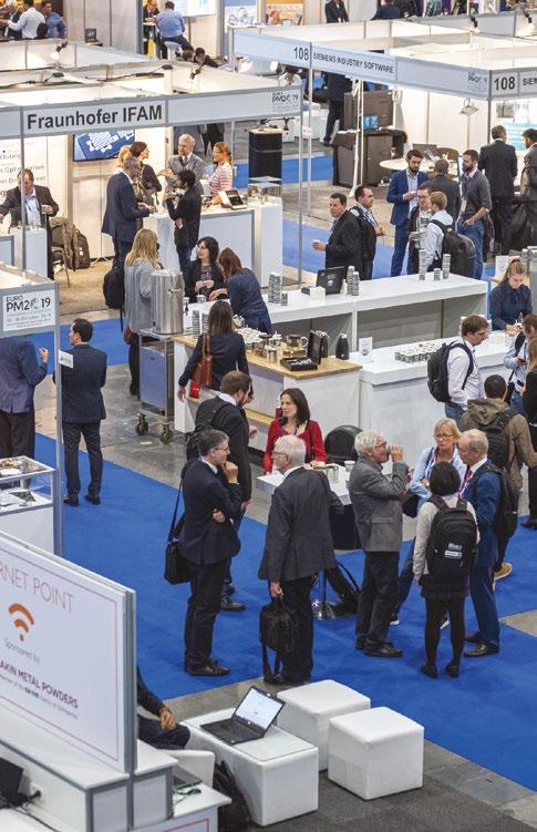
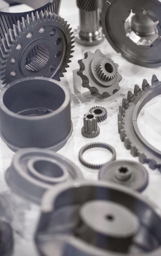
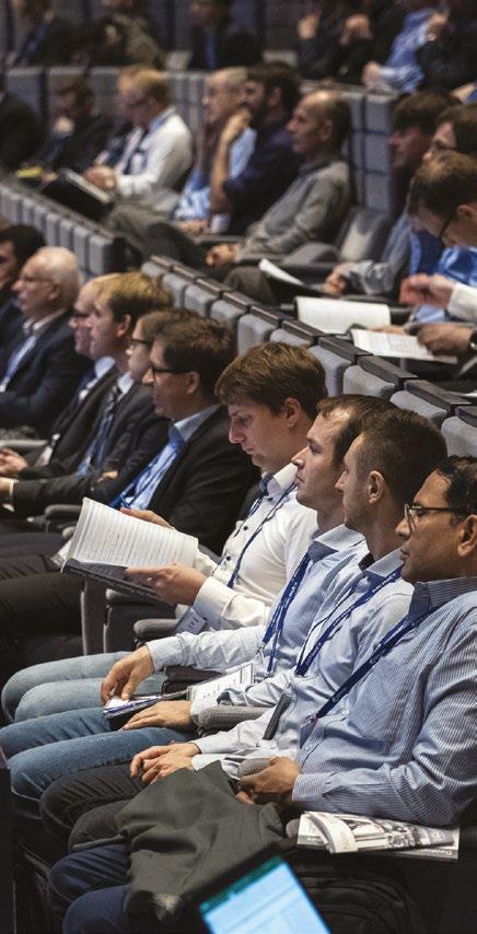


Congress & Exhibition europm2023.com 1 - 4 October 2023 Lisbon, Portugal EURO POWDER METALLURGY Reserve Your Exhibition Stand
LOW-CONSUMPTION HIGHLY VERSATILE IDEAL FOR ROUTINE TASKS


OPERATES ELECTRICALLY

PERFORMS WELL
SAVES MONEY AND GIVES EVERYTHING IS FAST


Your entry into the world of electric injection moulding: the GOLDEN ELECTRIC combines the unbeatable quality of our hydraulic GOLDEN EDITION with the efficiency of the electric drive. To the benefit of your customers and your controller.
www.arburg.com/info/pim