

Publisher & Editorial Offices
Inovar Communications Ltd

11 Park Plaza
Battlefield Enterprise Park
Shrewsbury SY1 3AF United Kingdom
Tel: +44 (0)1743 469909 www.metal-am.com
Managing Director and Editor
Nick Williams nick@inovar-communications.com
Group News Editor
Paul Whittaker paul@inovar-communications.com
Deputy Editor
Emily-Jo Hopson-VandenBos emily-jo@inovar-communications.com
Editor
Assistant
Charlie Hopson-VandenBos charlie@inovar-communications.com
Advertising
Jon Craxford
Sales Director
Tel: +44 (0)207 1939 749 jon@inovar-communications.com
Digital Marketer
Swetha Akshita swetha@inovar-communications.com
Production Manager
Hugo Ribeiro hugo@inovar-communications.com
Subscriptions
Metal Additive Manufacturing is published on a quarterly basis as either a free digital publication or via a paid print subscription. The annual print subscription charge for four issues is £150.00 including shipping. Rates in € and US$ are available on application.
Accuracy of contents
Whilst every effort has been made to ensure the accuracy of the information in this publication, the publisher accepts no responsibility for errors or omissions or for any consequences arising there from. Inovar Communications Ltd cannot be held responsible for views or claims expressed by contributors or advertisers, which are not necessarily those of the publisher.
Advertisements
Although all advertising material is expected to conform to ethical standards, inclusion in this publication does not constitute a guarantee or endorsement of the quality or value of such product or of the claims made by its manufacturer.
Reproduction, storage and usage
Single photocopies of articles may be made for personal use in accordance with national copyright laws. All rights reserved. Except as outlined above, no part of this publication may be reproduced, modified or extracted in any form or by any means without prior permission of the publisher and copyright owner.
Design and production
Inovar Communications Ltd.

ISSN 2050-9693 (Print edition)
ISSN 2050-9707 (Online edition)
This magazine is also available for free download from www.metal-am.com
© 2022 Inovar Communications Ltd
METAL ADDITIVE MANUFACTURING
Binder Jetting: AM’s second wave
When the Additive Manufacturing world left Euromold behind and Formnext rose from the ashes, the metals side of AM consisted almost entirely of Laser Beam Powder Bed Fusion (PBF-LB). The imposing exhibition pavilions of EOS, SLM Solutions, Concept Laser, Trumpf, Renishaw, 3D Systems and the like at the inaugural Formnext made a strong statement: PBF-LB technology is here, to be explored and to be developed. Few understood where the applications would be coming from nearly a decade later, but the very fact that there was a strong field of machine providers instilled a confidence that simply would not have existed had there just been one player.
These companies formed metal AM’s first wave, and around it was built an ecosystem of software, materials and postprocessing innovations. Core applications emerged, from conformally cooled tooling to motorsport, aviation and space applications.
At Formnext 2022 it very much felt that metal AM’s second wave was rising: Binder Jetting. The same fundamental necessity exists today – a field of players that together can make the clear statement that BJT technology is here and ready. Whilst ExOne, Desktop Metal and Digital Metal have been on the scene for some time - and should be credited with whetting the appetite of industry for BJT - the opening of sales for HP’s and GE Additive’s machines changes the perception of the technology significantly.
So, the question is how quickly will this wave rise? BJT benefits from materials developments from both Metal Injection Moulding (MIM) and PBF-LB. There are also MIM producers worldwide with the sintering expertise and customer bases to fast track the commercialisation of new applications. I’ve never been much of a gambler, but I think we might see some big surprises from BJT over the next two years.
Nick Williams Managing Director
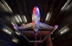
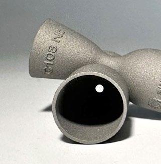
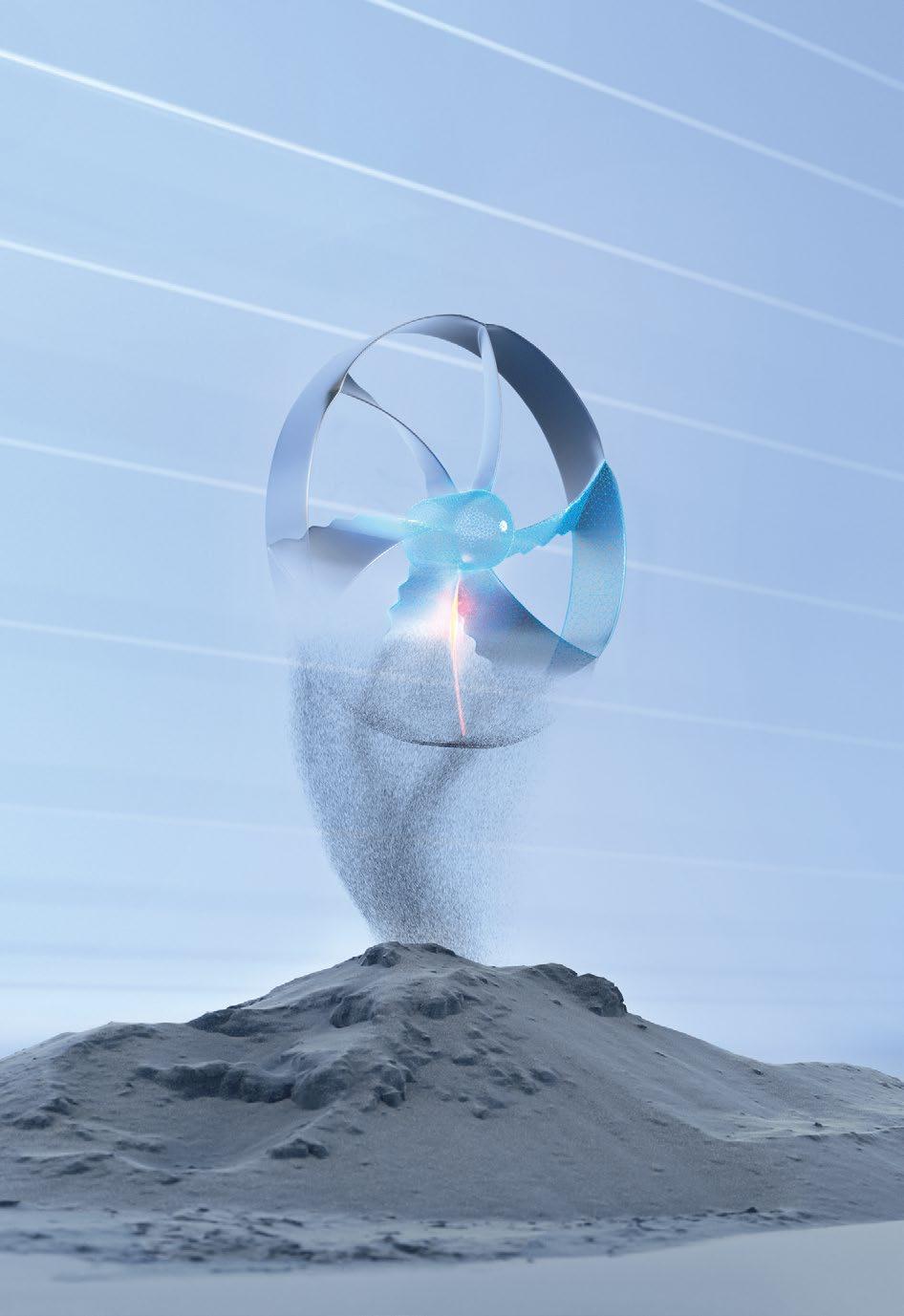
Cover image
A 2319 aluminium wind tunnel model featuring a nose cone produced by WAAM3D for the UK’s Aircraft Research Association (Courtesy WAAM3D)
GETPDF 3
Metal Additive Manufacturing | Winter 2022


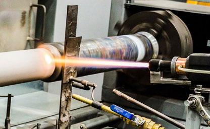
87 What happens when you take the powder out of AM? Charting the rise of wire-based DED with WAAM3D
While most people associate the advantages of AM with small- to medium-sized, complex parts, wire-based Directed Energy Deposition (DED) makes it possible to achieve geometric complexity on a huge scale.
Although the adoption rate for wire-based DED does not come close to that of the more widely known metal AM processes, this unique technology has advanced dramatically over recent years, and promises major advantages in a volatile global manufacturing landscape. Dr Filomeno Martina, CEO and co-founder of WAAM3D, explains more. >>>
99 Smart sensor-integrated parts by AM: A look at a novel possibility with industrial applications
Additive Manufacturing processes offer a high degree of design freedom. The Laser Beam Powder Bed Fusion of metals (PBF-LB/M), in particular, has established itself for series applications of complex-shaped parts in numerous industries.
In this article, Prof Dr-Ing Christian Seidel considers the next major step in PBF-LB, which could offer designers unknown potential: the production of sensor-integrated AM parts. Methods and solutions for the manufacturing of sensor-integrated AM parts are presented and industry-relevant case studies showcased, illustrating the potential offered by sensor-integrated ‘smart parts.’ >>>
GETPDF Metal Additive Manufacturing | Winter 2022 5 Vol. 8 No. 4 © 2022 Inovar Communications Ltd 14 91 128 117 40 Vol. 8 No. 3 © 2022 Inovar Communications Ltd
Contents Regular features... 11 Industry news >>> 164 Events guide >>> 167 Advertisers’ index & buyer’s guide >>>


© 2022 by 3D Systems, Inc. All rights reserved. Specifications subject to change without notice. 3D Systems and the 3D Systems logo are registered trademarks of 3D Systems, Inc. Make the existing better. Make the new possible. Repeatable, Reliable, and Scalable Additive Manufacturing Solutions Accelerate and de-risk your AM development • Function-Led Design for better optimized fluid flow and heat transfer • Speed to Market and Supply Chain Integration for a drastic reduction in lead time • Additive Manufacturing Expertise and Capability to rapidly progress from concept to successful production
107 Tailored materials for AM: How a ‘powder kit’ can achieve greater material diversity with fewer resources in PBF-LB
The use of metal AM is ramping up, and so, as a result, is the demand for metal powders. However, the variety of materials available remains relatively small. This is due, among other things, to the exacting requirements for the powders used, and the method of production. In addition, the production of smaller quantities of powder can be uneconomical.
In a project funded by the AiF, the IWM at Germany’s RWTH Aachen University and Fraunhofer IFAM have developed a sustainable ‘powder kit’ for the individual and robust production of metal powder mixtures with subsequent alloying during PBF-LB processing. The partners share their progress. >>>
117 QuesTek’s ICMD: Faster, cheaper, and better alloy development for Additive Manufacturing
Alloy development has evolved dramatically throughout history, from what was a game of ‘trial and error’ to a systematic approach driven by Design of Experiments and specialist software.
Now, the adoption of Integrated Computational Materials Engineering (ICME) is once again changing the way new materials are developed and deployed in today’s advanced manufacturing technologies.
QuesTek’s Keith Fritz, Director of Solutions Architecture, details how the company’s ICMD® platform is enabling faster, cheaper and more successful development of new alloys for metal Additive Manufacturing, as well as the build parameters to process them. >>>
125 NanoAL: Alloy development on an open parameter PBF-LB machine, from installation
through to Rapid Alloy Screening
When NanoAL, LLC, a company with a decade of aluminium alloy development experience, decided to speed up its development of alloys for AM, it turned to SLM Solutions’ SLM®125 PBF-LB machine. As NanoAL’s Matthew Simmers explains, the company needed a workhorse machine that fulfilled a number of requirements, from open parameters and material flexibility to specifications and build quality that closely mirrored larger, production-focused machines.
This article explores machine choice, installation, and operation in supporting NanoAL’s Rapid Alloy Screening (RAS) process. >>>
135
Using the Six Sigma method to optimise metal powder spreading in PBF-LB
In Laser Beam Powder Bed Fusion (PBF-LB), powder is applied to the build platform by a recoater unit performing a horizontal movement. Though not often the focus of research, the quality of powder layers has a significant influence on the quality of the final part, making the powder application process highly relevant to PBF-LB’s productivity and reliability.
A collaborative project between the Chair of Hybrid Additive Manufacturing (HAM) at the Ruhr University Bochum and the consulting firm MTS Consulting Partner has shown how the Six Sigma method can be used to improve the process of metal powder application in the PBF-LB process. >>>
GETPDF Metal Additive Manufacturing | Winter 2022 7 Vol. 8 No. 4 © 2022 Inovar Communications Ltd


Contact us TEKNA.COM AM METAL POWDER MANUFACTURER Plasma Quality Powder Traceability Industrial Capacity AS9100 and ISO 9001 CHARACTERISTICS Additive Manufacturing Metal Injection Molding Hot and Cold Isostatic Pressing Thermal and Cold Spray APPLICATIONS Subscribe to our mailing list www.tekna.com/webinars
145 Insights from R&D to part production: How CT analysis can advance metal Binder Jetting
In the race to optimise AM technologies for the creation of both breakthrough designs and direct part replacements, it is more necessary than ever that companies have access to the deep insights and data needed to advance part designs and processing at every phase of product development. Thanks to its ability to provide these insights non-destructively and in great detail, CT analysis provides an invaluable tool for the advancement of AM processes and their adoption.
Philip Sperling, Product Manager AM at Volume Graphics, explains how CT analysis can advance the development and adoption of metal Binder Jetting (BJT). >>>
151 Corrosion and wear resistance of materials processed by beam-based AM technologies
A technical session at the World PM2022 Congress & Exhibition, organised by the European Powder Metallurgy Association (EPMA) and held in Lyon, France, October 9-13, 2022, focused on the corrosion and wear resistance of materials processed using beam-based Additive Manufacturing. This session comprised three papers which looked at ways to improve these properties – both particular pain points for AM’s wider adoption – by way of chemicalmechanical surface polishing, adjusted laser power, and the development of new, wearresistant alloys for AM. Dr David Whittaker reviews the presented papers. >>>
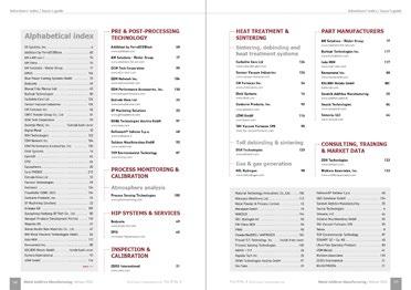
Advertisers’ index & buyer’s guide
Our advertisers’ index serves as a convenient guide to suppliers of AM machines, materials, part manufacturing services, software and associated production equipment.
In the digital edition of Metal AM magazine, available at www.metal-am.com, or via the Metal Additive Manufacturing app, simply click on a company name to view its advert, or on the weblink to go directly to its website. >>>

GETPDF Metal Additive Manufacturing | Winter 2022 9 Vol. 8 No. 4 © 2022 Inovar Communications Ltd
Regular features... 11 Industry news >>> 164 Events guide >>>
167


Metal Additive Manufacturing | Summer 2021 10 © 2021 Inovar Communications Ltd Vol. 7 No. 2 The future has arrived The DMP/PRO is here: a fast, accurate and versatile 3D printer that uses binder jetting technology, enabling volume production of everything from industrial components to medical and consumer products. Digital Metal® – a Markforged Group company •Groundbreaking 3D printhead 70,400 print nozzles ejecting 2 pL droplets, delivering speed and precision. •Repeatable and reliable Linear motors, air bearings stable, and robust diabase platform for high accuracy and tight tolerances. •High productivity Capable of printing 1,000 cm3 per hour and managed via a custom-built software platform, the DMP/PRO is designed for unbeatable productivity. Check out all the benefits at digitalmetal.tech/dmppro
Industry news
ALD announces large-format industrial PBF-EB machine
ALD Vacuum Technologies, GmbH, Hanau, Germany, has introduced a new large-format Electron Beam Powder Bed Fusion (PBF-EB) Additive Manufacturing machine, EBuild® 850. Said to be the largest PBF-EB system in the world, in its basic configuration the EBuild 850 is designed to produce metal parts with dimensions up to 850 x 850 x 1,000 mm.
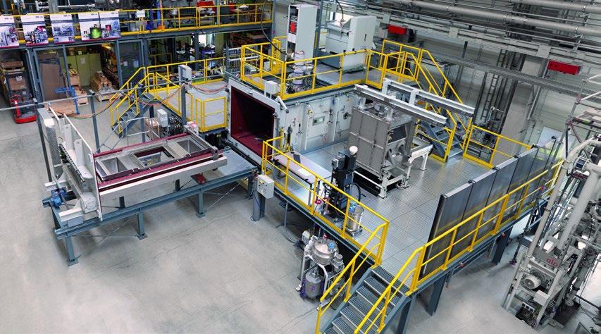
The system includes a retractable build chamber and a process chamber connected to an advanced powder application system, as well as mobile withdrawal and extraction units. A second build chamber may be added to this setup in order to perform the melt and cool down processes in one chamber while extracting the parts and powder from the second one and prepare it for the next build. The machine is designed to be completely vacuum-tight, enabling metal parts to be additively manufactured in vacuum or a controlled inert gas atmosphere.
“In order to overcome the limitations in component size, we have deliberately worked to expand the chamber design to many times the usual dimensions without sacrificing process quality,” stated Dr Fuad Osmanlic, VP – Additive Manufacturing at ALD. “Therefore, the high-precision withdrawal unit can position a powder bed weighing up to 15 t with an accuracy of approx. 0.01 mm and a total build height of approx. 1,000 mm.”
In order to apply the base material, the powder application system – which can also handle powders with low flowability – fills the build area ensuring a uniform powder distribution. The feeder platform is raised exactly by the height defined by the operator, ensuring that the powder fed to the rake remains constant. To prevent the high process
temperatures during melting from affecting the powder distribution, the application system is water-cooled.
“It was important to us that our powder application system can also handle powders with low flowability to increase the powder yield, which both saves resources and lowers the price per kilogram,” Dr Osmanlic added.
All chamber walls and components exposed to high temperatures are equipped with heat shields to keep energy consumption moderate during melting and avoid heat loss. All valves exposed to powder and metal dust have also been equipped with specific protection devices to ensure reliable functionality.
In order to meet the demands of industrial series production, the system has a high level of automation, as well as in-depth process monitoring, closed loop control, data logging, status indication, fault and alarm annunciation, along with safety interlocks to enable safe and efficient operation. A key feature is said to be the back-scattered electron imaging, as this offers the possibility to enable
automatic fault detection through high contrast layer imaging as well as constructing a digital twin as a 3D model. The entire process preparation, control and monitoring can be carried out via a PC or the built-in interface. This means that all relevant functions are visualised, in an effort to make the learning curve for the machine less steep. In addition, several local control panels installed in the operating area allow specific system functions to be executed locally. “Even with a high amount of automation we value operational flexibility and control where needed,” Dr Osmanlic explains.
Working with the buyer, the EBuild system can be tailored to equip the user with a turn-key system including process and production support. “Switching to new technologies in one’s production can be daunting and overwhelming without exploiting the full potential. Therefore, the EBuild® 850 is not an off-the-shelf plant, but specifically tailored to fully access the greater design freedom as well as enabling to produce what is needed, when it is needed,” he concluded.
An EBuild Pilot System is now available for customer process developments and trials.
www.ald-vt.com
| contents | news | events | advertisers | print sub | e-newsletter | GETPDF Metal Additive Manufacturing | Winter 2022 11 Vol. 8 No. 4 © 2022 Inovar Communications Ltd
ALD has begun operation of its large-format EBuild 850 (Courtesy ALD Vacuum Technologies)
Quality,


107 Commerce Road | Cedar Grove, NJ 07009 USA | +1 973.239.6066 | elnik.com
products. We offer: First Stage Debind Equipment (Catalytic, Solvent, Water) Debind & Sinter Furnaces (All Metal or Graphite) Elnik’s experienced team is driven to be the only partner you need for all your MIM and Metal AM equipment for 2022 and beyond.
Elnik’s innovations and experiences in all areas of temperature and atmosphere management have led us to become the leaders for the Batch-based Debind and Sinter equipment industry. We have applied these core competencies across a wide variety of industries through our 50 year history and look forward to the emergence of new technologies that will continue to drive demand for new innovative
Customer
We are driven by these values.
Experience and
Relationships
HP showcases Metal Jet S100 at Formnext

HP Inc, Palo Alto, California, USA, showcased its new Metal Jet Additive Manufacturing solution, post-processing capabilities, expanded Digital Manufacturing Network (DMN), new materials & recycling programme, and a variety of industrial production applications at this year’s Formnext exhibition.
Launched in September, HP’s Metal Jet S100 is reported to be enabling industrial customers, such as Domin Digital Motion, Lumenium, and Schneider Electric, achieve better productivity, low part cost, and highquality components.
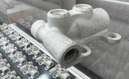
To demonstrate this, HP displayed a number of parts, including those built for John Deere, the global manufacturing leader of agricultural
and construction equipment. John Deere is using binder jetted valves, developed with GKN Additive, in its agricultural machinery. In addition to reported productivity gains and environmental benefits, the part is functional in extreme weather conditions. John Deere is also leveraging HP’s Multi Jet Fusion technology to optimise its production process, using AM prototypes to test and finetune components and parts such as windshield holders, reducing preassembly from thirty days to ten, delivery times by up to ten weeks, and overall production costs by between 20-25%.
“Our focus on innovation and sustainability is at the core of everything we do for our customers,”
stated Dr Jochen Müller, Manager Global Digital Engineering at John Deere. “We are proud to be among the first in the agricultural industry to leverage the benefits of 3D printing for both prototyping and final parts production. Leveraging industrial 3D printing platforms for polymers and metals, we are discovering opportunities to deliver more efficient, reliable, and sustainable equipment.” www.hp.com
Aubert & Duval announces new metal powder brand and relocation of Irun production site
Aubert & Duval, a subsidiary of the High Performance Alloys Division of the Eramet Group, based in Paris, France, has launched Stellar®, a new metal powder brand dedicated to Additive Manufacturing and announced plans for the relocation of its Irun, Spain, production site.
“These two announcements reflect our belief in the growth potential of the metal Additive Manufacturing market,” stated Eric Caridroit, president of Aubert & Duval Irun.
The Stellar brand is intended to embody all of Aubert & Duval’s
ambitions in the AM field, boosting its offer in a fast-growing market, with the rise of space applications and challenges of decarbonisation. The new range of high-temperature alloys Stellar ABD®-900AM, Stellar MHA3300®, Stellar AD730® are intended to represent a solution to enable the space, aeronautics and energy industries to develop new generations of turbines offering better energy and environmental performance.
Aubert & Duval is also moving to a new stage of its growth with a
relocation project of its metal powder production factory, scheduled for summer 2023. The new industrial site, with a planned 50% capacity increase, will be located in Oiartzun, Spain, 6 km away from its Irun factory. With this new industrial base, Aubert & Duval plans to increase its metal powder production to develop and produce customised AM alloys.
Adeline Riou, Global Sales Manager for metal powders at Aubert & Duval, concluded, “Through the combination of freedom of design and innovative materials, this technology offers great opportunities for weight reduction and high temperature performance. This value proposition is at the heart of our new Stellar brand.”
www.aubertduval.com
Metal Additive Manufacturing | Winter 2022 13 Vol. 8 No. 4 © 2022 Inovar Communications Ltd | contents | news | events | advertisers | print sub | e-newsletter | GETPDF Industry News
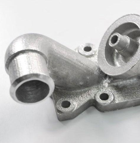
AM valves for John Deere’s tractor fuel system (Metal AM Magazine)
HP displayed its range of Additive Manufacturing solutions at Formnext (Courtesy HP Inc)
GE Additive introduces its highly anticipated Binder Jetting solution
GE Additive has announced more details of its much-anticipated Binder Jet Line and Series 3 Additive Manufacturing machine. With production deliveries expected to begin in the second half of 2023, the release of the system follows a four-year phase of customer collaboration and testing in an effort to ensure that the techology is ready for high-volume, serial production environments.
“In addition to a tangible business model, customers in fast-paced, highvolume manufacturing environments who are considering industrial-scale additive deployments also need to demonstrate positive financial and productivity impact, as quickly as possible. Customers shouldn’t have to reconfigure and tweak machines once they have been installed on their shop floor,” stated Josh Mook, chief engineer and innovation leader at GE Additive.
“We remain focused on only bringing technology solutions to market when they are ready, and can help our customers demonstrate return on investment and total cost of ownership. That is certainly the case with our new Binder Jet Line and the Series 3, which is reliable, safe, and meets their needs today and tomorrow,” he added.
According to the company, the Binder Jet Line Series 3 is capable of producing small or large complex
parts repeatably and reliably using Binder Jetting (BJT), with material properties that exceed casting equivalents. The Series 3 has a build envelope of 500 x 500 x 500 mm and a print speed of up to 9,000 cm 3/hr at 100 μm layers. It will process a wide range of metals, including stainless steels 316L, 304L, 17-4 PH & 441, copper and tungsten carbide.
Using GE’s proprietary binder systems, the Binder Jet Line is said to enable the user to depowder intricate parts without damaging fine features. Parts are also sintered within desired tolerances, thanks in part to GE Additive’s Amp™ software which can predict distortion.
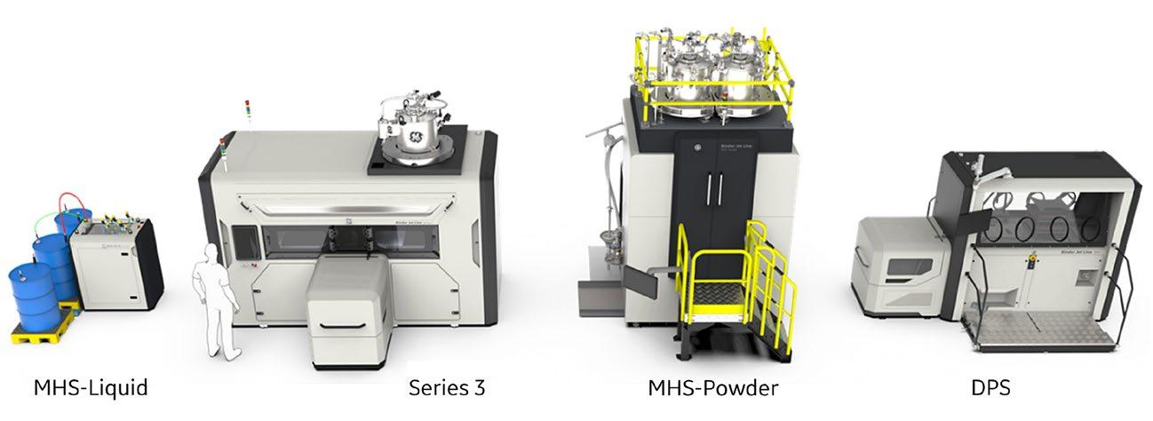
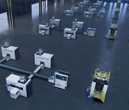
During the Binder Jet Line’s four-year development period, a group of strategic customer partners have contributed to the advancement of GE Additive’s BJT technology. Based on this input, a focus of the design has been to enable the eventual deployment of installations comprising fleets of forty to fifty to 100+ machines. This scalability will drive repeatable process quality, while minimising operator contact with equipment and materials.
The Binder Jet Line will be UL-listed and CE-certified, has a 100% inert and sealed environment, a fully closed-loop powder-free exposure, and is designed for compatibility with reactive and flammable powder and
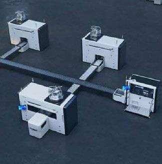
The Binder Jet Line offers scalability as a key advantage, and GE Additive envisages installations of forty to fifty to 100+ machines (Courtesy GE Additive)
binders. Other safety benefits include a fully independent and real-time safety system on board, constantly monitoring machine conditions, and real-time OPC UA data streaming for integration into factory MES and safety systems.
“During the Series 3 and Binder Jet Line’s development phase, we sought out customers who could give us honest, real-world insights from their high-volume manufacturing environments. We have taken their insights to complement our hands-on knowledge and experience of scaling additive production,” added Brian Birkmeyer, product line leader for Binder Jet at GE Additive. “The result is a modern, modular industrialised additive system – developed by additive users, for additive users – that delivers quality parts, at cost, at scale, and safely.” www.ge.com/additive
Metal Additive Manufacturing | Winter 2022 14 © 2022 Inovar Communications Ltd Vol. 8 No. 4 | contents | news | events | advertisers | print sub | e-newsletter | Industry News
GE Additive has released further details of its Binder Jet Line Additive Manufacturing machine (Courtesy GE Additive)
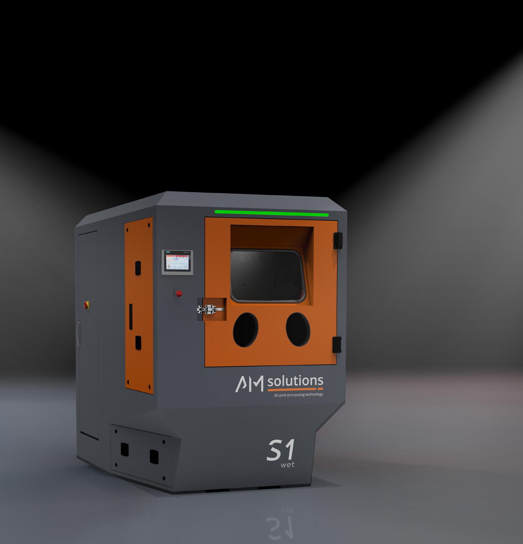
Surface finishing Metal Polymers Cleaning S1 WET – THE VERSATILE WET BLAST SOLUTION FOR CLEANING AND SURFACE FINISHING www.solutions-for-am.com 80 years of experience in surface finishing | Made in Germany 400 m² best in class test lab | Worldwide offices & service A brand of the Rösler Group READY FOR INDUSTRY 4.0
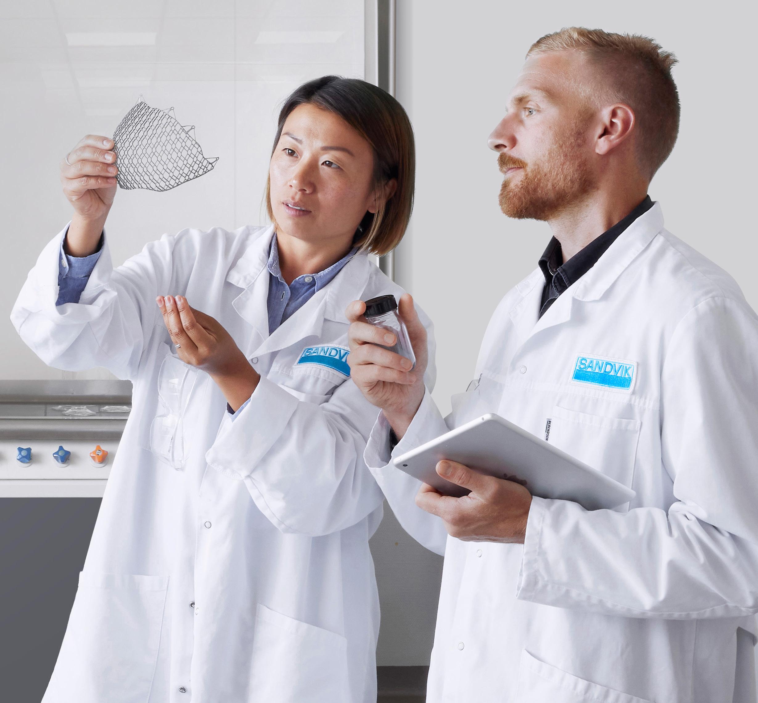
Sandvik to offer online metal powder ordering from Q1 2023
Sweden’s Sandvik has pre-launched a new online ordering ‘webshop’ for its range of Additive Manufacturing metal powders. Announced at Formnext 2022, Osprey® Online is expected to be fully launched in Q1 2023, and plans to offer a forty-eight-hour turnaround service as well as 24/7 technical support.
With more than 160 years of materials expertise and forty-five years of experience in powder atomisation, Sandvik is a leading provider of gas atomised metal powders for Additive Manufacturing and other metal powder-based processes. The company offers a wide range of alloys.
By registering interest via the Osprey site, customers can receive a 5% discount on their first order.
www.additive.sandvik.com
Tritone Technologies establishes

North American base
Tritone Technologies, Rosh Ha’ayin, Israel, has announced that it will be opening a US-based subsidiary to meet the needs of North American customers. Tritone Technologies North America is said to be a key step for Tritone’s global expansion, building on North American interest generated from the company’s participation in Rapid + TCT 2022, and comes following the APG’s installation of a Tritone Dominant machine.
The company has appointed Gal Barak as General Manager, Tritone Americas, who will join Ben Arnold, VP Business Development, NA. In his role, Barak will lead Tritone Technologies North America’s operation, addressing the company’s expanding global presence and helping to ensure superior service for customers in the NA region. Based in Florida, Barak has experience in sales and business development from global companies including Scitex, HP, and Stratasys. Tritone Technologies North America will be fully supported by Tritone Technologies, headquartered in Israel.
“At Tritone we see a growing demand for our products in NA,” stated Ofer Ben-Zur, CEO, Tritone Technologies. “Tritone made the decision to expand its global reach to address market needs. Tritone Technologies North America Inc will help to achieve our goals and reach our objectives. I wish Gal tremendous success in his mission to make Tritone a household name when seeking Additive Manufacturing solutions in the North America region.”
www.tritoneam.com

© 2022 Inovar Communications Ltd Vol. 8 No. 4 | contents | news | events | advertisers | print sub | e-newsletter | Examples in our copper portfolio: CU-OF: > 99.9% pure Cu YOUR PARTNER FOR HIGH QUALITY METAL POWDER www.metalpine.at THE ART OF SPHERICAL POWDER 29 Cu QUALITY MANAGEMENT SYSTEM EN 9100 incl. product design incl. requirements of ISO 9001
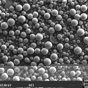
Equispheres introduces NExP-1 non-explosible aluminium feedstock
Equispheres, Inc, Ottawa, Ontario, Canada, has announced its development of a non-explosible aluminium alloy feedstock for Additive Manufacturing that reduces the hazards associated with the day-to-day handling of metal powders. Known as NExP-1, the material is designed for the production of additively manufactured aluminium parts.
The company explains that NExP-1 maintains the ability to produce high-quality builds at high throughput rates, but, unlike other metal powders for Additive Manufacturing, it is dust-free and characterised as non-explosible as per ASTM E1226, Standard Test Method for Explosibility of Dust Clouds. The material is also non-combustible as per the UN Manual of Tests and Criteria, Part 3, Subsection 33.2.1. for flammable solids.
“We have achieved these key safety properties without altering the quality of our material nor the chemical composition. In printing, this material performs just as well as our other aluminium powders, but it has the added benefit of being non-explosible and non-combustible,” stated Evan Butler-Jones, vice president – Product & Strategy for Equispheres. “It would almost be inaccurate to even call this a powder. It is almost totally free of dust; it flows like water and it is easy to clean off of equipment surfaces. It is a completely unique printing media for production Additive Manufacturing.”

The NExP-1 material is currently available in AlSi10Mg and the company has developed recommended parameters for additively manufacturing the new material, targeting several end-use applications.
Kevin Nicholds, CEO of Equispheres, commented, “We
are applying our technology to empower innovation in Additive Manufacturing. We anticipate this new safer aluminium material will be embraced by companies using AM in a production setting. This new breakthrough is a result of our ongoing efforts to make 3D printing more accessible and competitive with other manufacturing methods.”
Equispheres has a core team of metallurgists actively engaged in R&D and continues to develop processes and products to advance the technology of AM. The company’s Performance and Precision lines of aluminium powder demonstrate marked improvement in build speed and part quality, resulting in lower per-part costs. NExP-1, an addition to Equispheres’ Production product line relies on a technological breakthrough to address the handling properties of AM powders. www.equispheres.com
From Powder to Performance
Metal Additive Manufacturing | Winter 2022 17 Vol. 8 No. 4 © 2022 Inovar Communications Ltd | contents | news | events | advertisers | print sub | e-newsletter | GETPDF
ZEISS Additive Manufacturing Solutions is a holistic quality assurance solution that provides a comprehensive understanding of component quality and causes of failure, drives sustainable process improvements, and sets standards for future series production. www.zeiss.com/metrology/solutions/additive-manufacturing.html
ZEISS Additive Manufacturing Solutions
Industry News

MELD unveils 3PO hybrid additive and subtractive machine
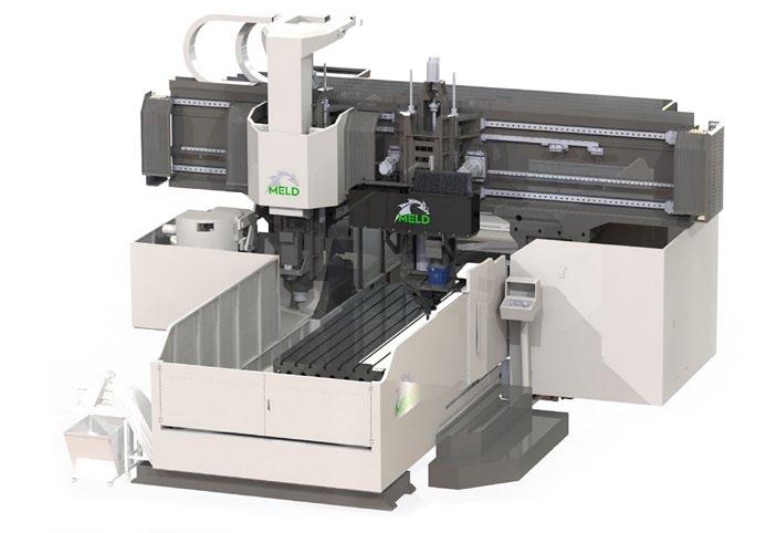
MELD Manufacturing Corporation, Christiansburg, Virginia, USA, announced its newest machine, 3PO, at Formnext 2022. The machine features a MELD Additive Manufacturing system with an integrated subtractive head. It has a large build capacity of 4 m x 2.7 m x 1 m (10.8 m 3) and eliminates the need for a separate subtractive machine.
3PO, named after Star Wars droids like the other MELD AM machines, offers a continuous Additive Manufacturing capability for large-scale parts. The subtractive capabilities include a standard 3-axis head, with an optional 5-axis head at a maximum travel speed of 12 m/minute.
MELD uses a patented Additive Manufacturing technology based on a process similar to friction welding, and can be used for the building and repair of metal components using off-the-shelf solid-state materials or powder. The process is capable of additively manufacturing large metal parts due to the fact that it is an open-atmosphere process and not sensitive to the operating environment or material surface condition.
The MELD process can utilise various materials, such as aluminium, titanium, steel and nickel-base superalloys, and is reputedly well suited to address several challenges facing the defence sector, along with other industries.
“In response to customer demand, we’ve increased the size of
parts possible with MELD, and added subtractive functionality to machine in features throughout the build,” stated Nanci Hardwick, CEO.
While 3PO is MELD’s first commercial off-the-shelf hybrid machine, it’s not the first machine that the company has been involved in that includes subtractive capabilities. The MELD technology is being deployed in a machine incorporating additive and subtractive technology for the US Army’s Jointless Hull Program.
www.meldmanufacturing.com
3PO from MELD features independent additive and subtractive manufacturing capabilities (Courtesy MELD)
MolyWorks opens sustainable AM powder production facility in Singapore
MolyWorks Materials Corporation, Los Gatos, California, USA, is expanding its global footprint with the establishment of a new metal foundry in Singapore to support the production of low-carbon metal powders and the development of new alloys, reports Singapore Times
Founded in 2015, MolyWorks Materials has developed a patented, compact recycling foundry and technology that recycles waste metals into raw materials for high-purity, sustainable powders suitable for Additive Manufacturing. To date, the company has successfully upcycled over twenty-five alloys.
The Singapore-based facility will serve as the company’s Asia-Pacific R&D and production hub, offering a wide range of metal powders, including small batches for custom alloys and R&D, and high-volume production for large-scale industrial applications. The facility is equipped with laboratories to support powder characterisation and testing services. “MolyWorks is very pleased to have found its own metal upcycled foundry in Singapore to provide a first source of sustainable metal powders for local businesses and the entire region,” stated Phil Ward, CEO of MolyWorks. “With strong interest and support from industry and the
Singapore government, this new local capability will help reduce metal waste while reducing carbon and improving the sustainability of the country’s metal parts production over time. We expect it to play an increasingly important role over time.”
Lionel Lim, VP of Technical Hardware and Equipment at the Singapore Economic Development Board, added, “MolyWorks’ move to use Singapore as a location to enhance its sustainable metal powder production for the region shows how a company can combine growth and environmental protection goals. Molyworks is excited about the new foundry’s role in partnering with the local Additive Manufacturing ecosystem to develop raw metal alloys for industrial use. This is timely, as we have a lot of work to do.”
www.molyworks.co
Metal Additive Manufacturing | Winter 2022 19 Vol. 8 No. 4 © 2022 Inovar Communications Ltd | contents | news | events | advertisers | print sub | e-newsletter | GETPDF Industry News
The
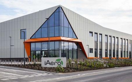
Markforged joins UK consortium at iAero


Markforged Inc, Boston, Massachusetts, USA, and its British reseller Mark3D have joined with aerospace supplier Leonardo UK, Yeovil College and the Somerset County Council to open and fully support a state-of-the-art Additive Manufacturing centre within the iAero Centre in Yeovil, Somerset, UK.

“One of the main aims of iAero is to provide an environment where new products and highvalue design and engineering solutions can be developed in collaboration with key industrial partners,” stated Austin Chick, head of iAero. “Engineers from all over the west of England will be able to use this first-class facility to further develop groundbreaking ideas and turn them into reality.”
Located on land owned by Leonardo and situated next to its UK end-to-end helicopter facility, the new iAero Innovation Centre provides a purpose-built research, design and innovation facility to support the growing aerospace sector in the region. As an anchor tenant and collaboration partner, Leonardo is currently utilising the centre with a number of projects already planned for the new capability.
The centre will be equipped with the full portfolio of Additive Manufacturing machines from Markforged, capable of processing an expanding range of engineering metals such as tool steels, copper and Inconel.
“The joint investment we see here today is further proof that the Aerospace and Defence industry in the South West of England is buoyant and ready to develop new products to support the world market,” stated Kevin Murphy, Markforged UK Territory Manager. “Markforged is delighted to be
The iAero Centre will open and fully support an AM centre (Courtesy Mark3D)
involved with this project and we look forward to helping both today’s engineer and the engineers of the future learn how Additive Manufacturing can turn ideas into reality.”

The iAero project also enables students from Yeovil College to use the facility. Students will be able to work side by side with people from industry, gaining valuable contextual experience in project-related applications. Students can also take advantage of the Markforged University Programme, adding online courses in AM to their list of qualifications and skills. As a partner of Leonardo, the Yeovil College team consider that understanding Additive Manufacturing solutions within practical scenarios is an invaluable experience for today’s young engineers.
Ian Weston, MD at Mark3D, concluded, “We expect this equipment to be utilised fully and it is important that the materials, consumables and spares are immediately available to the team. Our role is to facilitate a smooth running environment, provide advice with manufacturing decisions during the design process and help people in their learning phase. Additive is a really exciting place to be at the moment. This system offers the ability to design and manufacture in ways not possible a few years ago. This will enable companies in the region to upskill and become more competitive in their respective specialisms.”
www.markforged.com
Metal Additive Manufacturing | Winter 2022 20 © 2022 Inovar Communications Ltd Vol. 8 No. 4 | contents | news | events | advertisers | print sub | e-newsletter | Industry News Nickel Aluminium Additive Manufacturing MIM HIP Magnesium Silicon Aerospace Medical Automotive Cobalt Superalloys Titanium Nickel Aluminium Additive Manufacturing MIM HIP Magnesium Silicon Aerospace Medical Automotive Cobalt Superalloys MPP Ltd Metal Powder & Process Limited Tel: +44 (0)1323 404 844 info@metalpowderprocess.co.uk www.metalpowderprocess.co.uk PM Solutions by Design Ÿ Powders optimised for A M and other major processes Ÿ S pherical, free flowing, low oxygen content powders Ÿ We can arrange trials from R&D to pilot to production M P P Ltd manufactures both large and small lots, delivering powders in quantities as low as 5kg through to multi-tonnage orders. HERMIGA - Vacuum Inert Gas Atomiser (VIGA) supplied by PSI Ltd www.psiltd.co.uk Technical support to meet your powder requirements Ÿ A utomotive Ÿ A erospace Ÿ E nergy Storage Ÿ E nergy Generation Ÿ M edical Application of M P P Powders
Comprehensive
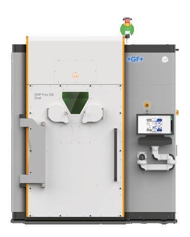
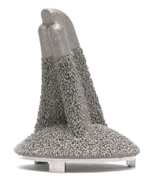
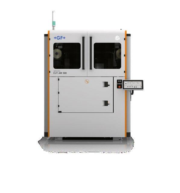
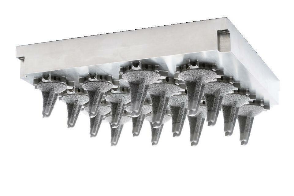
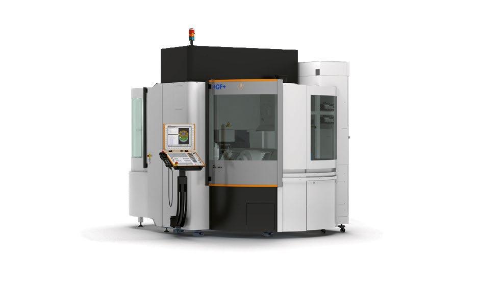
GF Machining Solutions AM Ecosystem From part design to finished product. 3DXpertTM All-in-one software Optimized print parameters database System 3R Tooling for AM Global Centers of Competences
solutions for 24/7 additive part production
production capacity and throughput
industry’s
conventional
part design
together
Increase your
with the
leading turnkey solution for additive manufacturing. Easy to integrate with
manufacturing equipment and capable of handling everything from
to serial production, GF Machining Solutions’ additive ecosystem works
seamlessly for cost-effective additive part production.
Machining operations MILL S 400 U Wire-EDM parts separation CUT AM 500 Laser Powder Bed Fusion DMP Flex 350 Dual
Learn more at www.gfms.com
Eplus3D adds EP-M1250 nine-laser metal AM machine
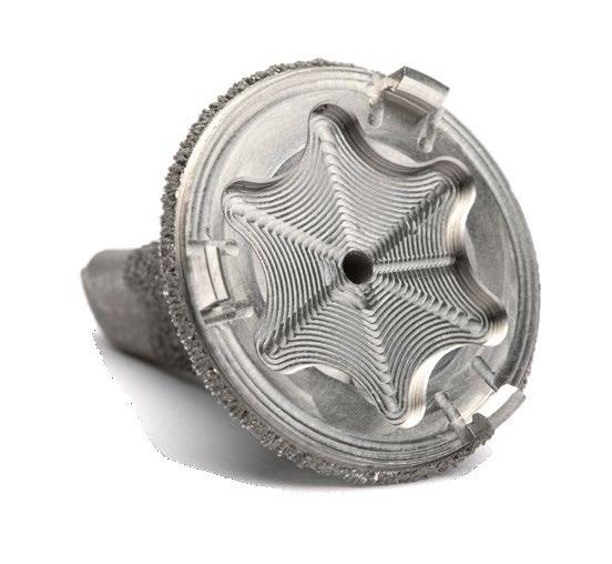
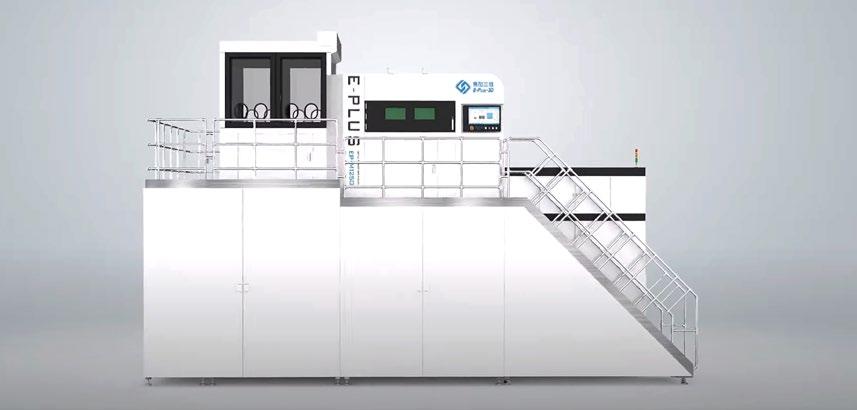
Eplus3D, headquartered in Hanzhou, China, has launched the EP-M1250, a large-format, multi-laser metal Additive Manufacturing machine. Featuring a 1258 x 1258 x 1350 mm build chamber and nine lasers, the new machine is expected to increase the development of multi-metre metal additively manufactured parts, whilst offering high productivity and reliability.
The EP-M1250 can operate with various metal powders, including titanium, aluminium and nickel-base alloys, maraging steel, stainless
steel, chrome cobalt alloys and other metals. The build rate for the new machine is reported to be up to 240 cm 3/h, producing parts with a density >99.9% and <5% deviation in mechanical properties.
To achieve homogeneous part properties across the build platform, the gas flow has been optimised and redesigned. The integrated process software also offers the ability to divide the build model into different sections, for which process parameters can be individually applied.
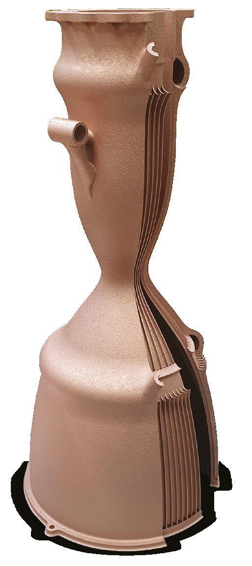
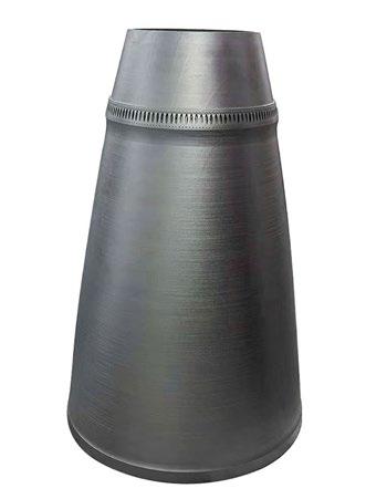
A rocket engine component produced on the new EP-M1250 metal AM machine (Courtesy Eplus3D)
Eplus3D has introduced the EP-M1250, its new large format, nine-laser metal AM machine (Courtesy Eplus3D)
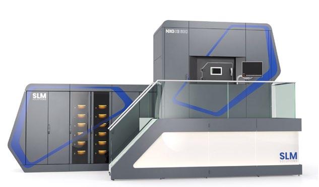
SLM Solutions announces its large-scale metal AM machine concept
SLM Solutions, Lübeck, Germany, has announced an Additive Manufacturing machine concept that will enable the production of large, high-quality
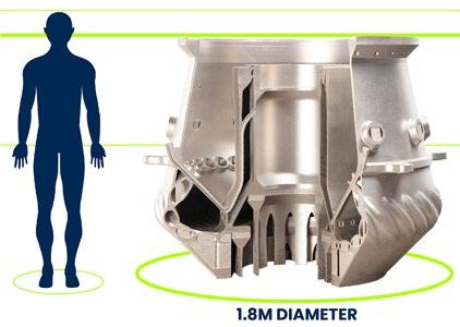
metal parts up to 3 m in length. The flexible system is reported to solve the problem of current build chamber constraints, allowing the production of either cylindrical parts with a diameter of 1.8 m and a height of 1.6 m or, alternatively, long parts with a dimension of up to 3 x 1.2 x 1.2 m.
Eplus3D states that its new EP-M1250 is suitable for the direct manufacturing of large, highprecision and high-performance parts in the aerospace, aviation, automotive and machinery sectors. To highlight its capability, the nine-laser metal AM machine has been used to produce a number of additively manufactured parts for the aerospace industry. These include a stainless steel rocket engine nozzle expansion section coming in at 1050 x 160 mm and an In718 rocket compartment at the size of 630 x 630 x 1100 mm (pictured above). www.eplus3d.com
seen in today’s systems. The new AM machine will offer a build rate of up to 330 cm 3/h.
SLM Solutions’ AM machine concept will enable a build rate of up to 330 cm 3/h (Courtesy SLM Solutions)
The large part machine concept contains a core unit and a build envelope that, being flexible in size, allows the manufacture of components in individual dimensions. Coupled with the advantages of SLM’s Additive Manufacturing technology, the machine will reportedly offer its users the possibility of tailored production without the limits
“This is yet another piece of game-changing technology that opens up new possibilities to transition applications to AM, by removing previously accepted geometrical restrictions,” explained Sam O’Leary, CEO of SLM Solutions. ”Every piece of technology we develop is testament to our incredible team of relentless innovators, who solve our customers’ manufacturing challenges and change the future of manufacturing forever.”
“It is not only a simple addition to SLM Solutions machine portfolio. It is a real revolution of manufacturing. We can’t wait to show the giant and massive metal parts. It’s almost unbelievable, but convince yourself” www.slm-solutions.com
Metal Additive Manufacturing | Winter 2022 22 © 2022 Inovar Communications Ltd Vol. 8 No. 4 | contents | news | events | advertisers | print sub | e-newsletter | Industry News
TO INDUSTRIALIZE ADDITIVE MANUFACTURING THE RIGHT PARTNER IS EVERYTHING
Our journey with additive manufacturing started 160 years ago... we just didn't know it then. But the material- and process knowledge we've been gathering since, is crucial to control the additive value chain. Through our joint forces with the BEAMIT Group, including 3T Additive Manufacturing, our offering includes the widest range of Osprey® metal powders on the market, leading expertise in post processing and metal cutting, and all relevant print technologies for metals – all under one roof. Together, we drive the shift toward sustainable manufacturing.
DISCOVER OSPREY® ONLINE – THE METAL POWDER WEBSHOP
Imagine being able to access premium metal powders for additive manufacturing directly from the source, from any device, at any time. Introducing Osprey® Online – the metal powder webshop stocked with powders and expertise. Just add to cart and we'll ship your order within 48 hours! Scan the QR code to register today, and enjoy 5% off your first order with us!

F o r m ore information visit MET ALP OWD ER .SANDVIK /WEB SHOP
Print today. Parts tomorrow. Make metal with the Rapidia System. 1201 Franklin St. Vancouver, BC V6A 1L2 Canada +1 604 267-0199 info@rapidia.com Office-friendly No loose powder or solvents, small footprint Design freedom Fast sintering of thick parts with or without infill. Evaporative support and water bonding, unlimited geometry Rapid turnaround Printer to sinter, no debinding www.rapidia.com
Elementum 3D partners with SLM Solutions for aerospace material development


SLM Solutions, Lübeck, Germany, and Elementum 3D, Erie, Colorado, USA, have entered a material development agreement to bring Elementum 3D’s range of high-performance alloys for aerospace and space applications to SLM’s customers. The agreement has also seen Elementum 3D acquire a twelve-laser NXG XII 600 Additive Manufacturing machine from SLM Solutions.


Through this partnership, the companies are collaborating to develop exclusive aluminium alloys 2024 and 6061 or aerospace-grade 7050 and 7075 for SLM technology. In this way, both companies are teaming up to further enhance material offerings on the twelve-laser technology used to build end-use parts travelling to space. Elementum 3D’s RAM technology is said to ensure safe processing and the successful outcome of additively manufactured parts with these difficult-to-use materials, and therefore opens completely new possibilities in terms of component size, processing speeds, and material properties.

“This strong partnership will enable our goal of empowering our customers to achieve theirs,” stated Sam O’Leary, CEO of SLM Solutions. “It will pave a path for an enhanced material portfolio enabling better performing applications and new business cases. We look forward to this partnership achieving new heights in AM and accelerating idea-to-production platform for our customers.”
Jacob Nuechterlein, president and founder of Elementum 3D, added, “We are pleased to announce this working agreement with SLM Solutions. With Elementum 3D’s ground-breaking materials and SLM Solutions leadership in production-sized printers for aluminiums, we can offer a full solution to organisations ready to take their ideas to production.”
www.slm-solutions.com www.elementum3d.com


Metal Additive Manufacturing | Winter 2022 25 Vol. 8 No. 4 © 2022 Inovar Communications Ltd | contents | news | events | advertisers | print sub | e-newsletter | GETPDF Industry News
medical industrial dental CoCr-Alloys Performance in Laser Powder Bed Fusion Convince yourself! S&S Scheftner GmbH Dekan-Laist-Straße 52 D-55129 Mainz +49 (0) 61 31-94 71 40 sales@scheftner.dental www.scheftner.dental
Elementum 3D and SLM Solutions intend to rapidly expand material selection for the NXG XII 600 (Courtesy SLM Solutions)
Sintertek launches Sinterjet M60 compact metal Binder Jetting machine
Sintertek, based in Istanbul, Turkey, has launched its latest metal Binder Jetting (BJT) Additive Manufacturing machine: the Sinterjet M60. With a build volume of 160 x 60 x 60 mm, and a print resolution of 1200 x 1200 dpi, the compact machine is said to enable the production of
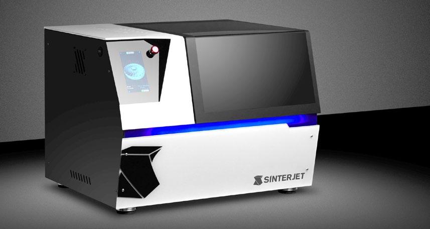
complex metal parts at a fraction of the cost of its competitors.
Measuring 550 x 350 x 450 mm, the Sinterjet M60 is small enough to fit on a table top and requires no dedicated electrical connections or gas supplies to operate. Capable of working with a wide selection of
materials, powders and binders, the BJT machine is said to be well suited to small workshops, R&D laboratories and academic institutes.
To enable minimal effort in handling powder, the Sinterjet M60 has a removable build box. This machine reportedly enables a new build – or changing of material at the end of a build – to be completed in seconds, increasing production throughput and reducing time to market.
Once the build process is complete, the additively manufactured parts within the powder will be removed from the machine with the build box and placed inside a curing oven. This will activate the binder and harden the part, readying it to be removed from the powder bed. From there, the cleaned parts are placed inside a sintering furnace to produce fully dense metal parts.
Sintertek has also developed an affordable sintering furnace to partner with the Sinterjet M60. This is expected to be available in 2023. www.sinterjet.com
GKN Aerospace acquires AM machine supplier Permanova Lasersystem
GKN Aerospace has acquired Permanova Lasersystem AB, Gothenburg, Sweden, a provider of advanced laser technology solutions and Additive Manufacturing machines. The acquisition is reported to be part of GKN Aerospace’s Engines business aim to transform its supply chain and offer more sustainable and advanced material solutions.
Permanova Lasersystem is a supplier of laser welding and Directed Energy Deposition (DED)
Additive Manufacturing machines to GKN Aerospace. The company states that the acquisition will strengthen its Additive Manufacturing offering, accelerate large-scale AM industrialisation and enable significant business growth.
GKN Aerospace also notes that this is a major milestone in its
sustainability journey, with Additive Manufacturing reducing material and energy usage by up to 80% compared to traditional manufacturing techniques. The widespread adoption of AM will be an important aspect of the aerospace industry’s commitment to achieving net zero emissions by 2050.
“Permanova represents a perfect strategic fit for us. Additive Manufacturing success requires three core capabilities: product know-how, process control and systems design,” stated Joakim Andersson, Engines president. “This acquisition gives us strategic control of the systems design element so that we now have deep expertise in all three areas. That is a game-changer for GKN Aerospace as it will enable us to accelerate the deployment
of AM at scale. Ultimately, that will help us grow our shares in existing and future Engine platforms and deliver a more sustainable future for aviation. We have an exciting journey ahead and I am delighted to welcome Permanova to the GKN Aerospace family.”
Håkan Grubb, CEO of Permanova Lasersystem, stated, “We are very excited to join the GKN Aerospace family. It is a company we have worked with for many years and have always had a strong partnership with and I am excited to work closely together to bring additive solutions to the market. Permanova Laser system is well recognised for its laser technology and integration expertise and together with GKN Aerospace we look forward to boosting the development of efficient and green fabrication solutions, powering the future of sustainable flight.”
www.gknaerospace.com www.permanova.se
Metal Additive Manufacturing | Winter 2022 26 © 2022 Inovar Communications Ltd Vol. 8 No. 4 | contents | news | events | advertisers | print sub | e-newsletter | Industry News
The new Sinterjet M60 metal Binder Jetting AM machine is small enough to fit on a table top (Courtesy Sintertek)

WWW.CNPCPOWDER.COM ©2022 CNPC Powder Group Co., Ltd. High Sphericity and Fluidity Low Oxygen and Low Nitrogen Levels High Eff iciency for Targeted Particle Sizing Higher Production Output with a much Shorter Production Cycle FROM THE STONE AGE TO THE SPACE AGE COPPER AND COPPER ALLOYS Specialized in Metal Powder
Kymera acquires CASL Surface Technologies Corp
Kymera International, a speciality materials company headquartered in Research Triangle Park, North Carolina, USA, has acquired CASL Surface Technologies Corp (CASL), headquartered in Alberta, Canada, a manufacturer of wear-resistant metallic and ceramic alloy coatings.

CASL develops and commercialises metallic coating process, alloy and capital equipment intellectual property purposed towards mitigating the impact of extreme wear on mission-critical industrial components. The company has two manufacturing facilities in Alberta and a production site in Houston, Texas. The acquisition is expected to enhance Kymera’s coatings and surface technologies product offerings.
“CASL’s leadership team has built a tremendous company of
talented people with industry-leading knowledge in thermal spray applications. This acquisition will allow us to accelerate our coatings initiatives both organically and through M&A,” stated Barton White, CEO of Kymera. “Combining the unique wear-resistant speciality materials Kymera has organically developed in-house, with the innovative alloys and application expertise of CASL, will give our customers end-to-end performance and value.”
Scott McLaughlan, president & CEO of CASL, commented, “CASL is thrilled to join the Kymera family where we expect the combination of our highly successful materials science-oriented teams, coupled with Kymera’s new product development focus and its global reach, will unlock the potential in CASL IP and generate extraordinary results.”
CASL is a manufacturer of wearresistant metallic and ceramic alloy coatings (Courtesy CASL Surface Technologies Corp)
Adam Shebitz, a partner at Palladium, added, “The acquisition of CASL, Kymera’s sixth under Palladium’s ownership, is aligned with the company’s value creation plan to become a leading speciality materials manufacturer and solutions provider. CASL’s offering complements the investments Kymera has made in its organic new product development capabilities, and unlocks exciting new growth opportunities.” www.kymerainternational.com www.caslsurftech.com
Continuous high temperature pusher furnaces for high volume 3D printed metal parts
Metal Additive Manufacturing | Winter 2022 28 © 2022 Inovar Communications Ltd Vol. 8 No. 4 | contents | news | events | advertisers | print sub | e-newsletter | Industry News The furnaces have both debind and sinter capabilities 103 Dewey Street Bloomfield, NJ 07003-4237 | Tel: 973-338-6500 | Fax: 973-338-1625 www.cmfurnaces.com info@cmfurnaces.com
Formnext 2022 attendance back to pre-pandemic numbers


Over the course of four days, Formnext 2022 once again brought the global Additive Manufacturing industry to Frankfurt, Germany. With attendees from ninety-six countries, the high proportion of international visitors (51%) and exhibitors (58%) demonstrated its status as the leading international trade fair for industrial Additive Manufacturing and advanced production technologies.
Now in its eighth year, the event included 802 exhibitors, up from 606 in the previous year, and over 51,000 m 2 of booked exhibition space. With attendance reported to be 29,581, up by 65.6% compared to 2021 (17,859), Formnext 2022 was virtually on par with pre-COVID levels.


“We are proud of the fact that Formnext has returned to its impressive pre-Covid level,” stated Sascha F Wenzler, VP – Formnext event organiser Mesago Messe Frankfurt GmbH. “We have once again demonstrated the importance of Formnext as the world’s premiere AM platform and the vital role of face-to-face interaction at Formnext for the further development of this highly innovative sector.”
The numerous world premieres and developments included novel AM technologies and new and improved AM machines, as well as new materials ranging from wood to ceramics, software solutions, service offerings, post-processing solutions, and much more. The programme of supporting events at Formnext 2022 was broader and more varied than before, leading visitors through the world of innovative startups, additively manufactured houses, and cutting-edge applications in medical technology. Recurring themes included the implementation of decentralised AM, the promotion of sustainable manufacturing solutions, and the growing maturity of industrial AM.
For the eighth time, the international Formnext Start-up Challenge recognised young companies from the world of AM for their business ideas
and technical developments. Visitors once again enjoyed the Pitchnext event, where start-ups competed for the attention of investors. The purmundus challenge competition celebrated its tenth anniversary, with a reception and a showcase of winners from the past ten years.
The Discover3Dprinting seminars were another popular event

during the exhibition, especially for newcomers to AM. The seminars are set to continue at various locations throughout 2023.
On November 14, the day before the start of the exhibition, the ASTM Standards Forum focused on the importance of standards and standardisation for Additive Manufacturing. On the same day, the Wohlers Report LIVE at Formnext 2022 event celebrated its debut.


Next year’s Formnext is scheduled to take place on November 7–10, 2023. www.formnext.com
Metal Additive Manufacturing | Winter 2022 29 Vol. 8 No. 4 © 2022 Inovar Communications Ltd | contents | news | events | advertisers | print sub | e-newsletter | GETPDF Industry News
GKN Aerospace to establish AM centre of excellence in Texas
GKN Aerospace has announced plans for a new North American Additive Manufacturing centre of excellence to be located in the Lone Star Commerce Center in Fort Worth, Texas, USA. The 9,300 m 2 facility will initially house research and development of AM technology for large-scale titanium aerostructures.
Existing equipment and personnel will be transferred from Oak Ridge National Laboratory’s Manufacturing Demonstration Facility in Tennessee to the new site in Texas. Plans are in place for an additional larger AM cell and, when at full capacity, the centre will house up to 100 personnel.
“We are very excited to bring our additive technology research to Fort Worth. With proximity to many of our major customers in Texas and across the US, this is the right place

for GKN Aerospace,” stated Shawn Black, GKN Aerospace’s president of Defense. “Along with a partnership with local government, we look forward to expanding our titanium Additive Manufacturing capabilities and pushing the boundaries of this technology for our customers and the aerospace industry.”
Over the next few years, GKN Aerospace expects to transform the facility into its fourth Global Technology Center to complement existing centres in Sweden, the Netherlands, and the UK.
GKN Aerospace has decades of experience in advanced aero-engine component development and large aerostructure expertise, with AM components currently flying on platforms across the civil, engines and space markets. The company is
an expert in the use of Laser Metal Deposition with wire (LMD-w), a Directed Energy Deposition (DED) technology, and recently completed its largest titanium AM demonstration part to date, with the production of a component measuring 2.5 metres and processed from approximately 45 kg of titanium wire.
www.gknaerospace.com
Metal Additive Manufacturing | Winter 2022 30 © 2022 Inovar Communications Ltd Vol. 8 No. 4 | contents | news | events | advertisers | print sub | e-newsletter | Industry News
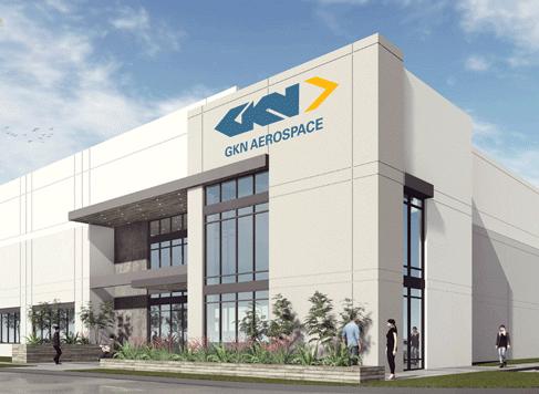
A rendering of the GKN Aerospace facility at Lone Star Commerce Center, Fort Worth, Texas (Courtesy GKN Aerospace)
Titomic launches D623 medium-pressure Cold Spray AM machine
Titomic Limited, Brisbane, Australia, has developed the Titomic D623 medium-pressure Cold Spray Additive Manufacturing machine. The company announced it has already received two orders for these, totalling AU$270,000.
The D623 is capable of depositing harder metals than the company’s D523 low pressure system, building on the earlier machine’s capabilities such as wear-resistant coatings and restoration of high-wear parts, among other updates.
The first sale was made to material science company Neue Materialien Bayreuth GmbH, Germany, which has extensive experience in additive and traditional manufacturing methods. This D623 has been built and delivered to Neue Materialien, with Titomic having
recognised this revenue. Neue Materialien intends to use the D623 to restore metal coatings & parts for their client base and for research & development.
The second D623 System has been sold to Universidad Rey Juan Carlos in Madrid, Spain, and is planned for delivery in the near future. The machine is intended to be used to add capabilities to the company’s current AM range, and will also be used extensively for research & development.
“It’s exciting to have received two commercial orders from two innovative and leading organisations. These sales further demonstrate the growing trust and demand for our technology that’s building in key markets, such as Europe,” stated Herbert Koeck, Managing Director,
The new D623 can be used for wear-resistant coatings and restoration of high-wear parts, among other applications (Courtesy Titomic)
Titomic. “The development of this system adds strength to our product portfolio, and further cements the company as a leading Cold Spray and advanced manufacturing provider. Titomic now has a significantly varied Cold Spray offering, enabling us to add value to a broad range of industries and manufacturers.” www.titomic.com

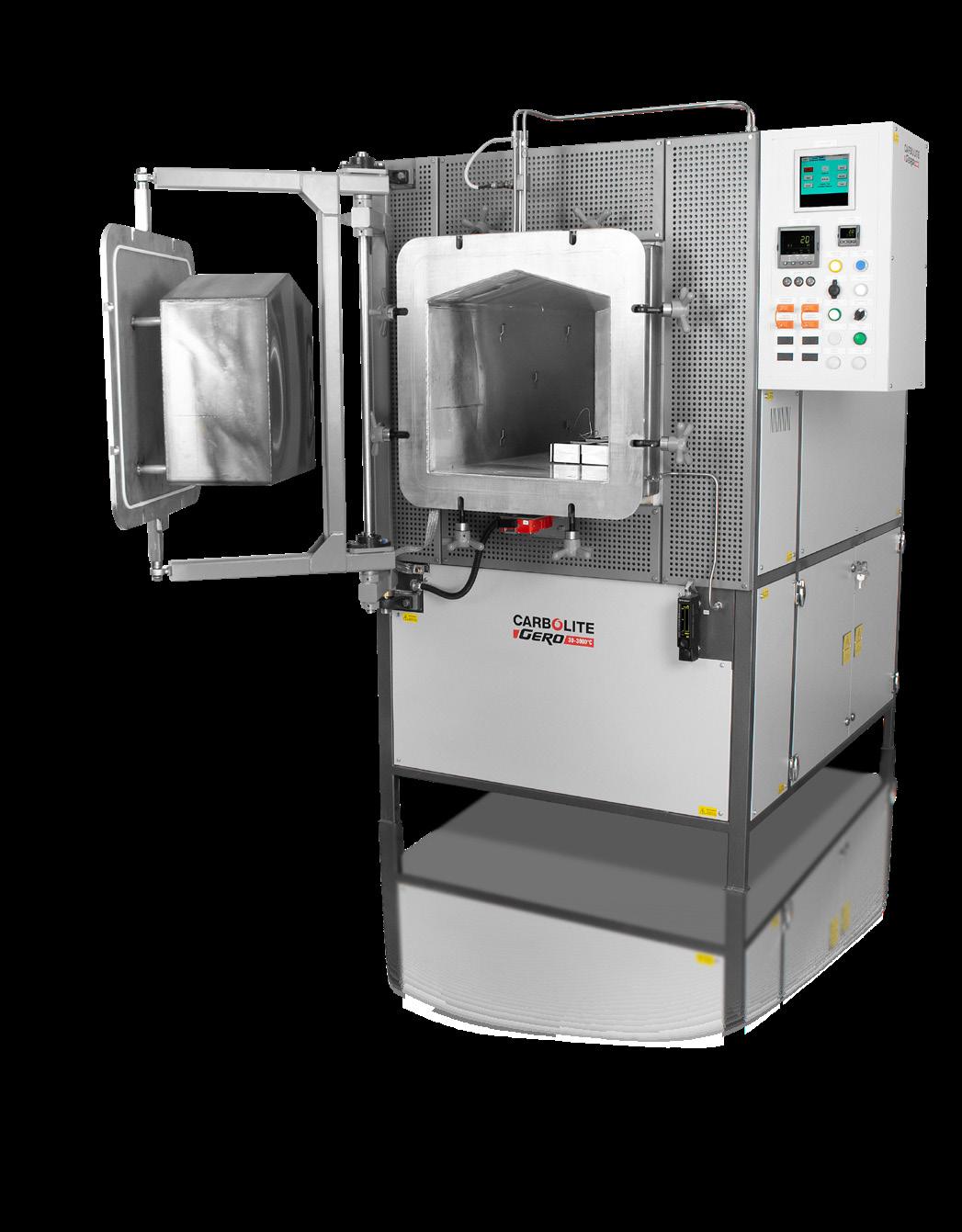
Metal Additive Manufacturing | Winter 2022 31 Vol. 8 No. 4 © 2022 Inovar Communications Ltd | contents | news | events | advertisers | print sub | e-newsletter | GETPDF Industry News www.carbolite-gero.com GPCMA – MODIFIED ATMOSPHERE CHAMBER FURNACE DEBINDING, PYROLYSIS & STRESS RELIEVING 3D PRINTED ADDITIVE MANUFACTURED PARTS Carbolite-Gero-Advert-GB-175x120.indd 1 04.06.2020 08:57:19
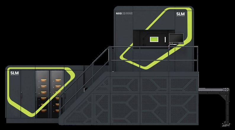
SLM Solutions announces NXG XII 600E featuring extended build envelope
SLM Solutions Group AG, Lübeck, Germany, has announced its latest Laser Beam Powder Bed Fusion (PBF-LB) Additive Manufacturing machine: the NXG XII 600E. Based on the NXG XII 600, the NXG XII 600E features an extended 1.5 m build envelope in the Z-axis, reportedly exceeding the size of its nearest competitor’s Z-build envelope by 50%. The company has accepted its first order for the new machine from Concurrent Technologies Corporation (CTC), the prime contractor for a US Air Force Research Laboratory (AFRL) project.
Customers who already have an NXG XII 600 AM machine installed, or are about to install one, have the option to upgrade their original AM machine to expand the Z-build envelope. Delivery of the NXG XII 600E is expected in 2023.
SLM Solutions states that customers are demanding larger metal AM parts, with serial production of complex geometries completed in hours or days rather than weeks and months. To meet these industry expectations, the NXG XII 600E is said to feature an end-to-end production workflow including external cool down unpacking to maximise machine uptime allowing job-to-job turnover under one hour versus the days reported on competing technology.
In addition, the NXG platform features SLM Open Architecture allowing maximum flexibility to tailor process parameters to optimise application results with maximum productivity using 90 μ m layer thickness and beyond in commonly qualified materials that can be processed including IN718, AlSi10Mg, TiAl6V4 & copper alloys. Support-free
AM with Free Float capability offers maximum freedom in design, and reduces the need for both support structures and post-processing time by up to 90%. SLM.Quality performs efficient and robust quality assurance with documentation, process qualification, and part certification with the ability to generate a quality report in a reported two clicks, and fully document process data & validate part quality.
“We are pleased to continue our long-term partnership with SLM,” stated Edward J Sheehan, Jr, CTC president and CEO. “SLM is clearly a leader in the Additive Manufacturing equipment arena, and we look forward to collaborating and expanding the possibilities of Additive Manufacturing for defence applications in this exciting opportunity in support of critical AFRL mission requirements.”
SLM
Parmatech receives aerospace AS9100 certification
Parmatech, an ATW Company, headquartered in Petaluma, California, USA, has announced the addition of AS9100 certification to its ISO 9001 quality system for the manufacturing of metal components. Included in this certification
is metal Additive Manufacturing, Metal Injection Moulding, secondary machining operations and special processes.
AS9100 certification, equivalent to EN 9100 and JIS Q9100, is designed to meet the needs of any supplier,
Sam O’Leary, CEO for SLM Solutions, commented, “These are the partnerships that are a testament to SLM Solutions’ ethos; it is only in close collaboration with them that we can push the limits of innovation. To take a market leader like that of the NXG XII 600 as a blueprint, extend the envelope to 1.5 m, coupled with the precision and reliability of our systems, and our hands-on support allow our customer to develop with agility–almost at the Mach-speed that we are designing this system to build parts for. We are especially pleased to be teamed with CTC, a highly regarded premier research and development organisation with an outstanding record of securing technology transition successes.”
www.slm-solutions.com
manufacturer or service provider at any level of the supply chain in the aerospace industry.
Parmatech uses Metal Injection Moulding to manufacture components for a wide range of customers in the healthcare, aerospace, telecommunications, defence and industrial markets.
www.atwcompanies.com/ parmatech
Metal Additive Manufacturing | Winter 2022 32 © 2022 Inovar Communications Ltd Vol. 8 No. 4 | contents | news | events | advertisers | print sub | e-newsletter | Industry News
Solutions has announced the NXG XII 600E which is based on the NXG XII 600 metal AM machine and features an extended 1.5 m build envelope in the Z-axis (Courtesy SLM Solutions)
Outstanding performance


Special stainless steels, nickel and cobalt alloys produced by VDM Metals are used in many of today‘s key technologies for the safe and reliable handling of corrosive and high-temperature processes and procedures. In addition to exceptional materials, available as powder for additive manufacturing in a wide range of particle fractions, we o er you various first class services.
Materials for the future. vdm@vdm-metals.com www.vdm-metals.com


6K Additive to increase AM metal powder production capacity; partners with Incodema3D for metal powder and recycling
6K Additive, a division of 6K, North Andover, Massachusetts, USA, has announced its intention to significantly increase metal powder production capacity at its Burgettstown, Pensylvania, facility. The expansion includes adding four new UniMelt microwave plasma systems for powder production, as well as the addition of a new material feedstock preparation building. 6K also announced a powder supply agreement and recycling partnership with Incodema3D, Freeville, New York.
The capacity increase is in response to a reported growth in demand for the company’s nickel, titanium and refractory powders. The additions are expected to help 6K meet its customers’ needs for the coming twelve to thirty-six months.
“Global unrest has shed a major spotlight on our nation’s supply chain vulnerability for critical materials,” stated Frank Roberts, 6K Additive’s president. “This, in combination with our consistent product quality, sustainability benefits, and the fact that we are a domestic supplier, have contributed to increased commercial activity with key strategic customers. This expansion will help us meet customer demands in the coming years and ensure efficiencies in current and future operations.”
The addition of the feedstock preparation facility is expected to provide the company with vertical integration of feedstock sizing for nickel and titanium in the same location. This will help to streamline operations and provide faster delivery, and ultimate control and quality of the powder produced.
The Burgettstown plant currently produces a full range of powders including nickel 718 & 625, titanium-64, stainless steel and copper, as well as capabilities to produce aluminium alloys. 6K Additive also runs two dedicated UniMelt production systems co-located in the company’s parent headquarters in North Andover producing tungsten, rhenium and niobium-based alloys for hypersonic, defence, and rocket applications.
Eric Martin, Chief Operating Officer for 6K Additive, commented, “The ability to meet the demands of our customers in both quality and delivery is paramount for our organisation. The addition of a feedstock preparation facility and the added UniMelt production capacity will help to create a consistent operational flow to meet this demand. However, I am equally excited to be able to bring on more talent to the organisation with as many as thirty-five additional employees planned. It’s
great for our organisation as well as the tri-state area.”
6K Additive’s mission is to provide a solution for global decarbonisation in producing performance materials that are critical to production in markets such as aerospace, defence, medical and industrial applications. The company recently released results from a life cycle assessment conducted by Foresight Management comparing the environmental impact of 6K’s UniMelt microwave plasma technology to current atomisation technologies in the production of metal powders. The results showed upwards of a 91% reduction in energy use and a 91.5% reduction in carbon emissions when using the 6K UniMelt process.
Partners with Incodema3D for metal powder and recycling
A strategic AM powder supply agreement and recycling partnership with Incodema3D has also been announced.
Following increased demand and larger volume orders, predominantly from aerospace and defence customers, Incodema3D sought to secure a domestic metal powder supply that met strict quality standards, as well as a solution for recycling its used powder and parts. 6K Additive, through its UniMelt plasma microwave powder production system, is able to provide high volumes of domestically manufactured powder and a route to sustainably recycle Incodema3D’s used metals through its Powder Buy Back programme.
“We are talking to clients now about projects for 2023 that will require ten tons of metal powder per month,” stated Kevin Engel, Incodema3D director of Additive Manufacturing and metrology operations. “When you’re going through that volume of powder, recycling becomes imperative, and sustainability is key to our business. By recycling our used powder with 6K Additive we have been able to drive down our contribution costs for material by 15% already.”
www.6kinc.com/6k-additive/ www.incodema3d.com
Metal Additive Manufacturing | Winter 2022 34 © 2022 Inovar Communications Ltd Vol. 8 No. 4 | contents | news | events | advertisers | print sub | e-newsletter | Industry News
6K Additive has announced plans to increase metal powder production capacity at its Burgettstown, Pensylvania, facility (Courtesy 6K Additive)
3D printing of large pure copper parts
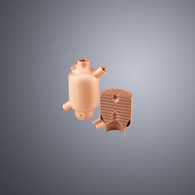
TruPrint 5000 Green Edition: The unique combination of our green laser and additive manufacturing system - now also for large 3D printed parts. Benefit from outstanding thermal properties and electrical conductivity ( >100 %IACS) as well as highest quality and productivity of printed pure copper and copper alloys.
More information www.trumpf.com/s/additivemanufacturing
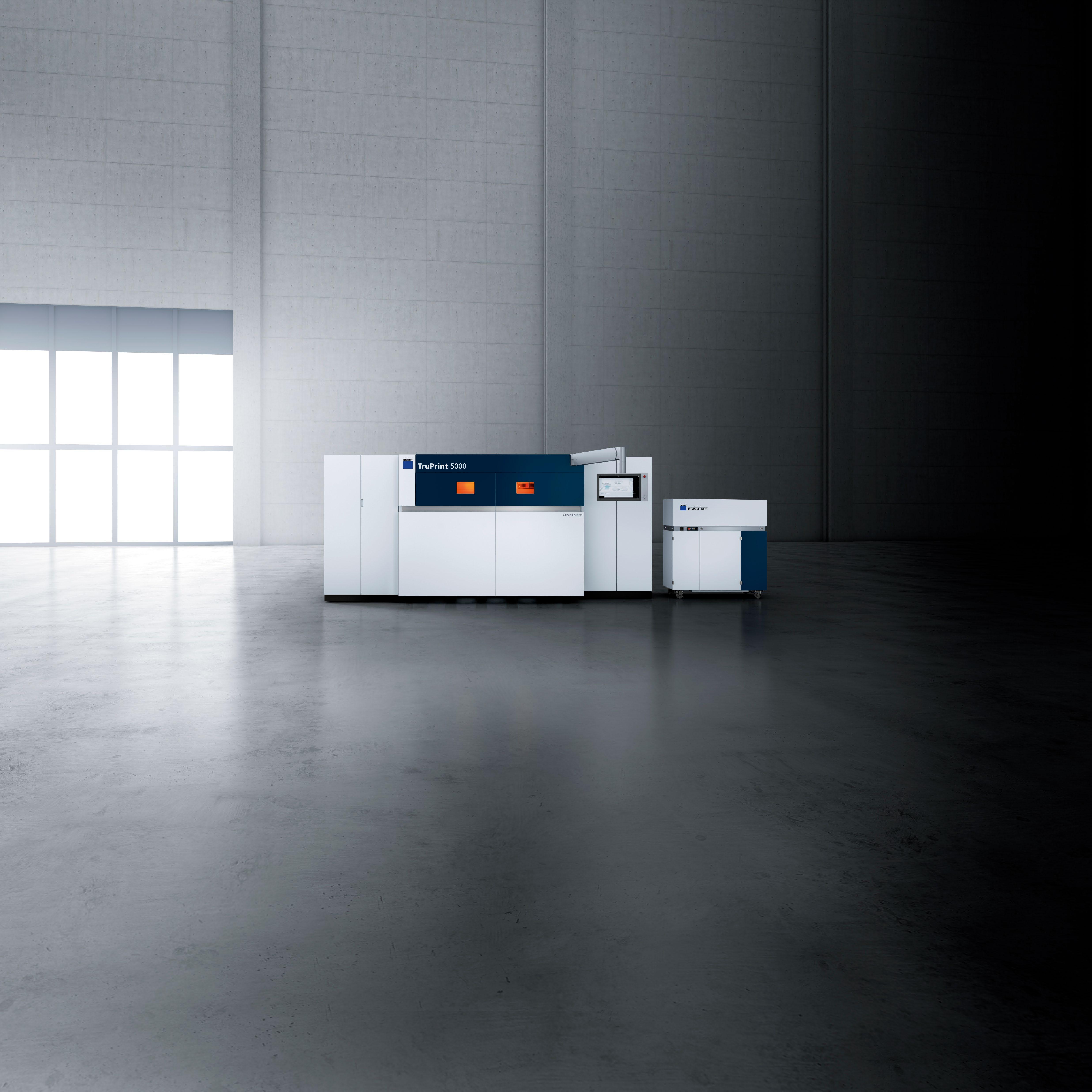
with the TruPrint 5000 Green Edition
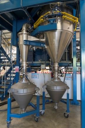
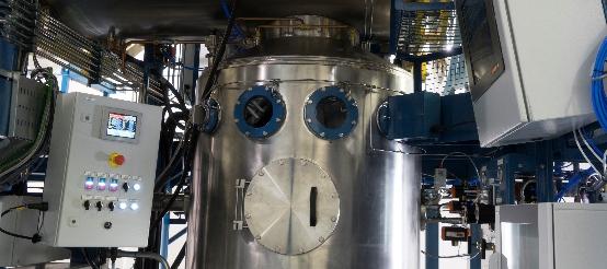
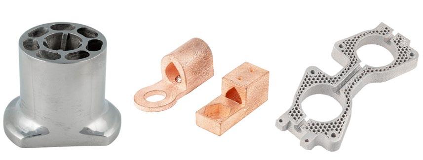
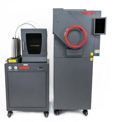
Rapidia showcases its two-step metal AM process to European market
Exhibiting at this year’s Formnext for the first time was Canada’s Rapidia, bringing its two-step metal extrusion Additive Manufacturing technology to the European market and launching its Advanced Vacuum Sintering Furnace.
Established in 2016, Rapidia has developed what it claims is a simple, fast, and accessible method of Additive Manufacturing metal, centred on a water-based feedstock. In 2020, the company partnered with ExOne to establish the Metal Designlab, complementing ExOne’s Binder Jetting product line. Following ExOne’s acquisition by Desktop Metal in late 2021, that partnership ended and Rapidia has returned to independent distribution of their hardware and feedstock.
Rapidia’s two-step AM technology, first revealed in 2019 and since refined, sees water-bound metal and ceramic parts go directly from the build stage into a furnace, without a debinding stage. The process is made possible by HydroFuse, a water-based paste containing metal or ceramic powders, which does not require debinding before final sintering.
Along with the AM machine and feedstock, the company has also launched its Advanced Vacuum Sintering Furnace. This furnace offers partial pressure sintering in
argon and is said to yield excellent metallurgy. Non-flammable forming gas mixtures are also compatible.
Parts can be sintered directly from the AM machine in approximately twelve hours, meaning components can be available within sixteen to twenty-four hours from the beginning of a build.
Leveraging the open architecture of the technology, research partners have formulated specialised pastes with Rapidia materials and have developed their own sintering cycles for the furnace, the company has stated. The research community has said that the straightforward system allows them to focus on these new materials and techniques.
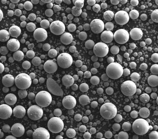
Off-the-shelf materials from Rapidia include stainless steels 316L and 17-4 PH, offering corrosion resistance and strength, along with Inconel 625 for high-temperature
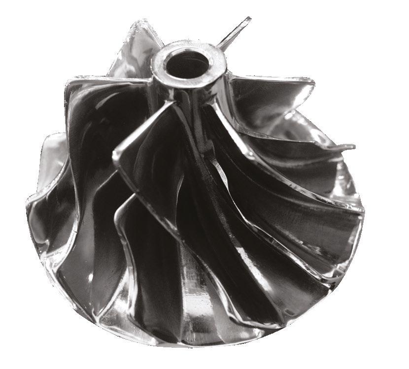
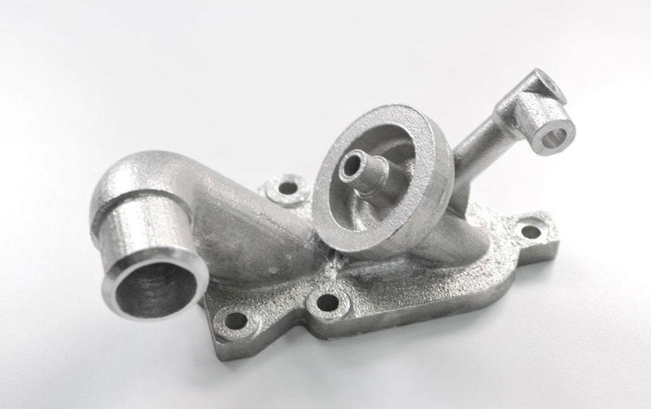
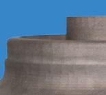
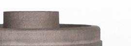
Rapidia uses a two-step metal extrusion Additive Manufacturing technology and recently launched its Advanced Vacuum Sintering Furnace (Courtesy Rapidia)
performance and enhanced corrosion resistance.
The team is currently engaging with European customers to bring the first system to the market in Q1 of 2023.
www.rapidia.com
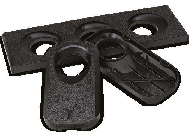
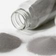
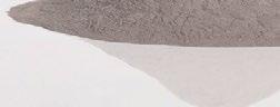
Rapidia can process a wide range of metals (Courtesy Rapidia)
Hawk Ridge acquires Access Manufacturing Systems
Hawk Ridge Systems, based in Mountain View, California, USA, a provider of end-to-end Additive Manufacturing services, has acquired service and manufacturing solutions provider Access Manufacturing Systems Inc, Salem, New Hampshire, USA. This move is said to be part of a strategic initiative to expand Hawk Ridge’s nationwide services and solutions.
“Our goal has always been to help customers enhance their manufacturing efforts,” stated David Dulong, president of Access Manufacturing Systems. “Hawk Ridge Systems shares that same commitment and now our customers will have access to a wealth of resources from an industry leader.”
Dale Ford, president and CEO of Hawk Ridge Systems, added, “For decades, we have had a passion for
putting our customers first. That is a passion we share with the team at Access Manufacturing Systems, Inc. We’re excited to welcome their customers and serve them with the tools, training, and resources that Hawk Ridge Systems is known for.”
Hawk Ridge Systems’ product line includes Markforged and HP Additive Manufacturing equipment. Access Manufacturing Systems offers services using manufacturing software including CAMWorks and SolidWorks, as well as equipment from Markforged and Rize.
www.hawkridgesys.com
Metal Additive Manufacturing | Winter 2022 37 Vol. 8 No. 4 © 2022 Inovar Communications Ltd | contents | news | events | advertisers | print sub | e-newsletter | GETPDF Industry News
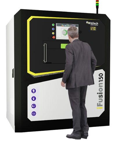
Intech Additive Solutions updates iFusion150 and launches iFusion325
Intech Additive Solutions Pvt Ltd., Bangalore, India, has launched the second-generation of its iFusion150 (formerly known as iFusion SF1) metal AM machine, along with the new, larger, iFusion325.
The iFusion150 is a small-format Laser Beam Powder Bed Fusion (PBF-LB) metal AM machine with a build volume of 150 (diameter) x 180 mm (height). The 500 W laser – which can be upgraded to 700 or 1000 W – enables users to manufacture at higher build rates and layer thicknesses, enabling nesting and stacking of more parts per build.
“With the launch of the new second-generation iFusion150, we hope to expand in international markets like those in Asia Pacific and Europe, and we look forward to collaborating with relevant distributors in these regions,” stated Pradeep Nair, VP – Sales.
The new iFusion325 is a mid-size PBF-LB machine with a build volume of 325 x 325 x 420 mm, said to be one of the largest in its class. It is available with either single or multi-laser configurations and offers full-field scanning. The machine brings high levels of automation to increase operational efficiency, including auto -
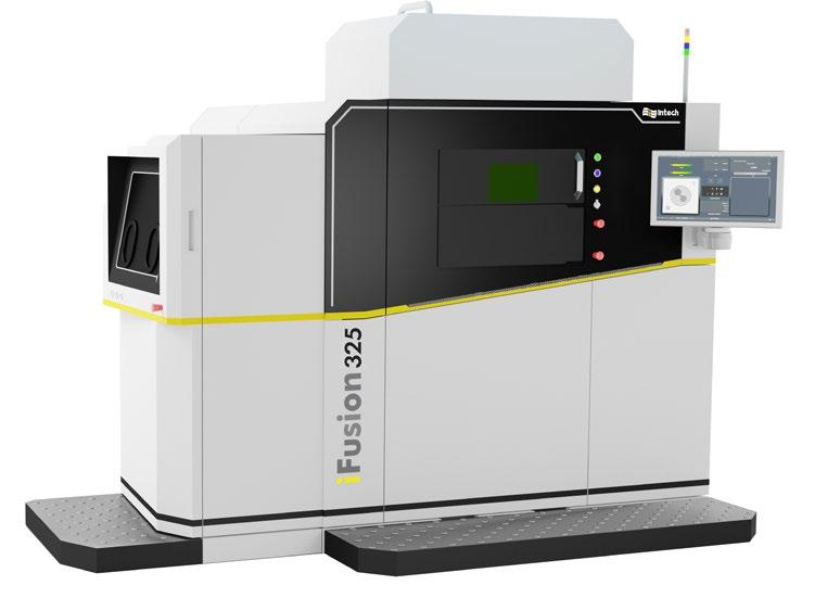
mated powder handling, part removal and powder sieving. It is equipped to produce parts from a wide range of materials and metal alloy powders, including aluminium, titanium, copper, stainless steel and Inconel.
“Following the successful launch of iFusion150 2nd gen, we are excited to showcase the iFusion325... This solution will cater to diverse AM requirements, which is ideal for various industry verticals,” added Sridhar Balram, founder and CEO of Intech Additive Solutions. “We anticipate this machine to be one of the bestselling products from our portfolio in the future.”
Both machines include Intech’s AMBuilder, an integrated pre-build design software for Powder Bed Fusion-based Additive Manufacturing. www.intechadditive.com
Incus and Micro MIM sign reseller agreement
At Formnext 2022, Incus GmbH, Vienna, Austria, and Micro MIM Japan Holdings Inc., headquartered in Osaka, Japan, signed a sales representative agreement which will expand Incus’s offering into Japan. With a detailed knowledge of the debinding and sintering process, Micro MIM is ideally positioned to support customers of Incus’ sinter-based Additive Manufacturing machines.
Incus provides solutions for the Additive Manufacturing of high-performance metals via a lithography-based metal manufacturing (LMM) technology, defined as a Vat Photopolymerisation process (VPP) by ISO/ASTM. This process is said to produce parts with high surface aesthetics and similar material properties found in Metal Injection Moulding.
Micro MIM Japan Holdings Inc is a MIM parts manufacturer specialising in the mass production of metal parts up to 30 mm in all dimensions.
In 2021, the companies entered into a partnership which provided an Incus Hammer Lab35 metal Additive Manufacturing machine to enable Micro MIM to produce functional prototypes and offer small runs of parts to its customers.
www.incus3d.com www.micro-mim.eu
Metal Additive Manufacturing | Winter 2022 38 © 2022 Inovar Communications Ltd Vol. 8 No. 4 | contents | news | events | advertisers | print sub | e-newsletter | Industry News
Intech Additive Solutions has launched its iFusion325 PBF-LB metal Additive Manufacturing machine (Courtesy Intech Additive Solutions Pvt Ltd)
The second Generation iFusion150 (Courtesy Intech Additive Solutions)
For improved sustainability, variety and performance, choose forAM®
In the world of metal powders, Höganäs is always at the forefront of innovation. From more sustainable production processes to new and patented powder compositions, we are dedicated to offering you the optimal solutions while reducing environmental impact. With forAM ®, our range of metal powders designed for additive manufacturing, we can offer powders designed for any application.
The forAM ® range includes nickel, iron, cobalt, copper, titanium and aluminium powders in a variety of grades and compositions. Combining optimal powder performance with improved sustainability is a priority for Höganäs. In addition to our material innovations, we have also committed to Science Based Targets and are founding members of the Additive Manufacturing Green Trade Association, demonstrating our ongoing committing to leading sustainable transformation in our industry.
3203HOG www.hoganas.com
—
Sintavia develops proprietary niobium AM material parameters
Sintavia, LLC, Hollywood, Florida, USA, has developed proprietary material parameters for alloy C103, a high-performance niobium alloy suited for rocket, jet and satellite
propulsion applications. The refractory metal, which can be difficult to additively manufacture, was developed on an M290 AM machine from EOS, and marks the twenty-ninth proprietary material developed by Sintavia for use by its aerospace, defence and space OEM customers.
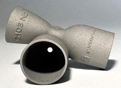
industry-leading mechanical properties. When combined with Sintavia’s equally best-in-class design and additive production capability, our C103 parameters offer our customers a high-quality and reliable industrial solution for extreme temperature applications.”
Sintavia has developed parameters for alloy C103 for rocket, jet and satellite propulsion (Courtesy Sintavia)
“Due to its extremely high melting point, niobium is widely recognised as an excellent material for space propulsion applications, specifically reaction control thrusters and attitude control thrusters,” stated Pavlo Earle, Sintavia’s VP of Technology Engineering. “With this development, Sintavia is able to offer its space customers components that embody
Rio Tinto partners
Rio Tinto, Sorel-Tracy, Québec, Canada, has partnered with the government of Canada to invest up to US$537 million over the next eight years in an effort to decarbonise its Rio Tinto Fer et Titane (RTFT) operations and to position the business as a centre of excellence for critical minerals processing. The partnership is intended to support technological innovations that represent a first step towards reducing greenhouse gas emissions from RTFT’s titanium dioxide, steel and metal powders business by up to 70%. It is also expected to progress initiatives to diversify RTFT’s product portfolio.
The Government of Canada will invest up to $162 million to support these initiatives through its Strategic Innovation Fund (SIF), which supports large-scale, transformative, and collaborative projects that will help position Canada to prosper in the global knowledge-based economy. The partnership will support projects including BlueSmelting, increasing scandium production and adding titanium metal to Rio Tinto’s portfolio.
BlueSmelting
The BlueSmelting project is an ilmenite smelting technology that could generate 95% less greenhouse gas emissions than RTFT’s current reduction process, enabling the production of high-grade titanium dioxide feedstock, steel and metal powders with a reduced carbon footprint. A demonstration plant is currently under construction at the RTFT metallurgical complex in Sorel-Tracy to test and validate this technology developed by scientists from Rio Tinto’s Critical Minerals and Technology Centre. Construction of the demonstration plant – which is expected to have the capacity to process up to 40,000 tonnes of ilmenite ore per year – is expected to be completed in the first half of 2023.
If fully implemented, the BlueSmelting project will reportedly have the potential to deliver a reduction of up to 70% in RTFT’s overall greenhouse gas emissions, a decrease of approximately 670,000 tCO 2e compared to 2021 – the equivalent of removing 145,000 cars from the road.
The mechanical properties of Sintavia’s C103 include an as-built density of 99.94% and a Z-direction elongation of 32% after a standard stress relief cycle. Full performance data for Sintavia’s C103 parameter set can be found on the company’s website.
Earle added that Sintavia is currently developing proprietary standards for other refractory materials for use across the aerospace, defense and Space industry. www.sintavia.com
Increasing scandium production
Rio Tinto also announced plans to quadruple its production capacity to reach up to 12 tonnes of scandium oxide per year. New modules will be added to the existing plant, which uses a new process to extract high purity scandium oxide from the waste streams of titanium dioxide production, without the need for any additional mining. The $22-26 million project is expected to start producing scandium oxide in 2024.
Adding titanium metal Rio Tinto is partnering with other titanium industry participants to advance the development of a new process for extracting and refining titanium. The company is setting up a pilot plant at the RTFT metallurgical complex to validate this low-cost process, which reputedly requires no harmful chemicals and does not generate direct greenhouse gas emissions. The plant is expected to be completed by the end of 2023.
This project has the potential to increase the production of raw titanium metal in North America, while strengthening the security of supply for this critical mineral for Canadian and US manufacturers. www.riotinto.com
Metal Additive Manufacturing | Winter 2022 40 © 2022 Inovar Communications Ltd Vol. 8 No. 4 | contents | news | events | advertisers | print sub | e-newsletter | Industry News
with Canadian government in $537 million decarbonisation investment
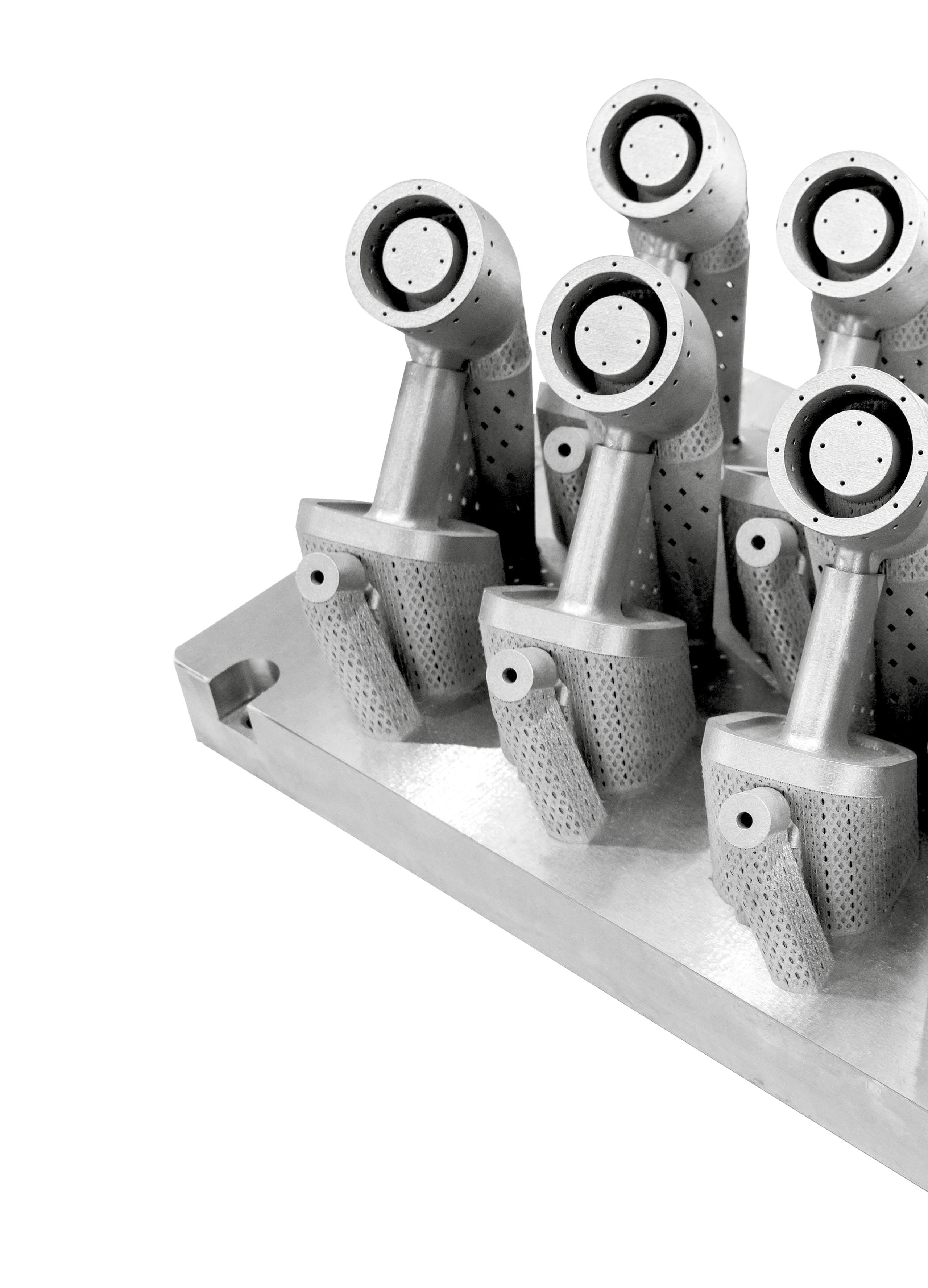
www.bodycote.com Bodycote provides a complete service solution for metal parts built by the additive manufacturing process, including stress relief to minimise distortion and residual stress, EDM to prepare the component for hot isostatic pressing (HIP), heat treatment or HIP to remove microporosity, and associated quality assurance testing. Reduction in rejection rates and inspection costs Fatigue properties on par with wrought material Significant improvement in fatigue strength, fracture toughness, and tensile ductility 100% reduction in porosity possible Improved machined surfaces and consistency in properties Improved microstructure
VALUE TO ADDITIVE MANUFACTURING the partner of choice for additive manufacturing heat treatment | metal joining | hot isostatic pressing | surface technology
ADDING
Additive Manufacturing Services to Help You Scale
While the world is busy imagining the future of additive manufacturing, Burloak is busy living it.
We have the facilities, the network and the logistics to scale your production and help you realize the efficiencies and advantages of additive manufacturing.
Learn what sets us apart at burloaktech.com
Industry News
Manufacturing execution system provider AMFG receives $8.5M funding
AMFG Corp, Austin, Texas, USA, a provider of manufacturing execution system (MES) and workflow automation software for Additive Manufacturing, has secured $8.5 million in funding, led by Intel Capital.
With this new funding, AMFG states that it will continue to help companies scale and streamline their AM processes as well as strengthen AMFG’s position as a provider of autonomous manufacturing. In addition, as part of the recent funding, Intel Capital investors Jennifer Ard and Alexandra Farmer are joining AMFG’s Board of Directors.
“Additive Manufacturing is at an inflection point, shifting from
rapid prototyping to large-scale part production and penetrating nearly every major manufacturing-centric industry, including automotive, industrial & consumer goods, healthcare, as well as aerospace and defence,” stated Jennifer Ard, Managing Director and Head of Investment Operations at Intel Capital. “AMFG has become the go-to solution to help companies unlock the full potential of Additive Manufacturing to keep up with increasing demand. We’re excited to be part of Keyvan Karimi and his team’s journey.”
This funding round follows a year of milestones for AMFG. These include expanding into the US by establishing a global headquarters in Austin, Texas, which places the
Daido Steel releases new die steel-based powder for Additive Manufacturing
Daido Steel Co., Ltd., headquartered in Nagoya, Japan, has announced the availability of DAPTM-AM LTX die steel-based metal powder for Additive Manufacturing, the second product in its DAPTM-AM (Daido Alloy Powder – for Additive Manufacturing) series of metal AM powders. The gas atomised powder offers low oxygen content and high flowability, and is particularly suitable for large-sized products.
Developed specifically for Laser Beam Powder Bed Fusion (PBF-LB) Additive Manufacturing, DAPTM-AM LTX is based on SKD61 (JIS steel), which is widely used for dies and moulds. The new alloy enables the production of components which have been historically difficult with conventional die steel-based powders. Unlike maraging steel powders, DAPTM-AM LTX does not contain cobalt, and tests show that once additively manufactured, the material
company in direct contact with the region’s dramatically shifting manufacturing scene, and making several strategic hires to the growing AMFG team. With this funding, AMFG will advance its vision to pioneer a path into the future of autonomous manufacturing.
The company explains that HP Inc is partnering with AMFG to improve workflow and management capabilities in its Additive Manufacturing business. Ryan Palmer, Global Head of Software, Data and Automation, and HP Personalization & Industrial Business, commented, “Efficient connectivity and easy access to systems data is key to accelerating the journey towards digital AM production. We’re excited to partner with AMFG to help our customers bring more control, automation and visibility into their AM operations.” www.amfg.ai
has the same performance as moulds made from traditional SKD61 steel.
In April 2021, Daido launched DAPTM-AM HTC, a high thermal conductivity metal powder and the first product in the DAPTM-AM range. DAPTM-AM HTC is a cobalt-free die steel-based powder that suppresses cracking and enables highperformance moulds to be additively manufactured. However, DAPTTM-AM HTC is only suitable for additively manufacturing moulds up to 150 mm square, any larger than this is more suited to DAPTM-AM LTX, being ideal for parts exceeding 150 x 150 mm. www.daido.co.jp
Tempering hardness of DAPTM-AM LTX compared to H13 (Courtesy Daido Steel)
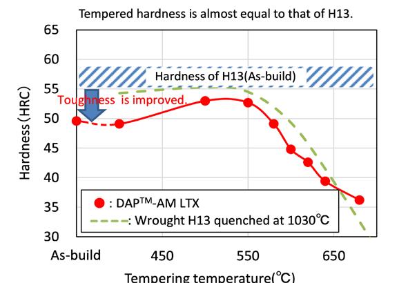
Thermal conductivity of DAPTM-AM LTX compared to H13 and maraging steel (Courtesy Daido Steel)
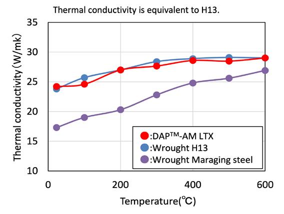
Metal Additive Manufacturing | Winter 2022 43 Vol. 8 No. 4 © 2022 Inovar Communications Ltd | contents | news | events | advertisers | print sub | e-newsletter | GETPDF Industry News
3D Systems adds two highperformance metals to range
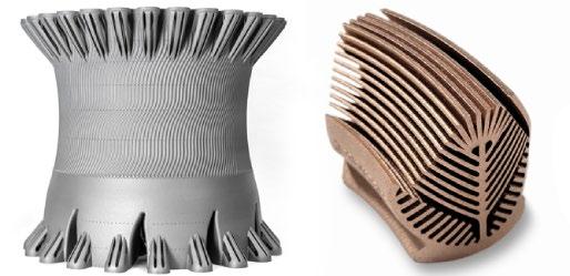
3D Systems, Rock Hill, South Carolina, USA, has announced the addition of Certified HX and Certified CuCr2.4 to its materials portfolio. Both materials are certified for use with the company’s DMP Flex and DMP Factory 350 Additive Manufacturing machines; HX is also certified for the DMP Factory 500 in an effort to address applications requiring high strength and corrosion-resistance in industries such as energy, industrial gas turbines, aerospace, defence and automotive.
Certified HX is a high-performance nickel alloy that contains a higher percentage of molybdenum (up to 9.5%) than other nickel alloys, enhancing its strength and resistance to corrosion, creep deformation, cracking, and oxidation in hot zone environments. This material is suited to applications with a service temperature of up to 1200°C and is said to be ideal for producing tall, large parts with integrated cooling and flow channels in optimal orientation in demanding industries. Possible applications include hot zone stator blades and integrated stators, impellers, turbine vanes, drilling tools, and combustion components that benefit from the high service temperature of the
HX material. The material’s parameters were developed in collaboration with GF Machining Solutions before they underwent testing and optimisation by GF Casting Solutions using real-world applications.
“The DMP Factory 500 together with the new printing parameters for the HX nickel alloy allows us to scale our Additive Manufacturing services by delivering large cross-section parts such as combustion chamber casings, stators, and impellers,” stated Marco Salvisberg, Business Development Manager, Additive Manufacturing, GF Casting Solutions. “The high heat deflection temperature of the HX material combined with the surface smoothness, part accuracy, narrow tolerances, and high repeatability of the DMP Factory 500 printing process addresses the essential performance requirements of these parts and critical features such as cooling channels. With direct metal printing technology, we can outperform our competitors when it comes to the quality of metal series components. Our customers rate DMP part quality as the best in the industry today.”
The Certified CuCr2.4 is a high-strength, corrosionresistant copper alloy that is said to be significantly stronger than pure copper and easier to additively manufacture. Its high part density (typically 99.9%) and conductivity after heat treatment make CuCr2.4 suitable for heat management and cooling systems in the high-tech, consumer goods, automotive, and aerospace & defence industries, especially when strength is also a requirement.
“Our Application Innovation Group (AIG) works alongside our customers to design the best Additive Manufacturing solution to address their application challenges,” said Dr David Leigh, EVP and CTO for Additive Manufacturing, 3D Systems. “Defining the right solution starts with our team collaborating with customers to select the best material to meet the part’s required performance and mechanical properties. Continued investment in our materials portfolio will help increase the number of applications available to help our customers’ demands — enabling them to accelerate their innovation and maintain their competitive advantage. The addition of Certified HX and Certified CuCr2.4 bolster our metals materials portfolio in support of our customers’ evolving application needs.” www.3dsystems.com www.gfms.com
Metal Additive Manufacturing | Winter 2022 44 © 2022 Inovar Communications Ltd Vol. 8 No. 4 | contents | news | events | advertisers | print sub | e-newsletter | Industry News
3D Systems has added Certified HX and Certified CuCr2.4 to its materials portfolio (Courtesy 3D Systems)


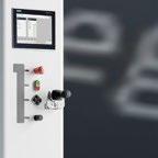


solukon.de NEW For SFM-AT800-S and SFM-AT1000-S SPRPATHFINDER® Depowdering Software SPR-Path nder® Automatic calculation of part motion without any human programming
Kymera International awarded 2022 EcoVadis silver for sustainability
Kymera International, a speciality materials company headquartered in Raleigh, North Carolina, USA, has been awarded a silver, meaning the company has ranked in the top 25% of sustainable organisations according to EcoVadis.
“Kymera is committed to ESG and this tremendous accomplishment is proof that, even in a challenging manufacturing environment, sustainability is possible. Well done team,” stated Barton White, CEO of Kymera International.
EcoVadis provides a platform through which companies can have their sustainability performance independently assessed. Customers can access this evaluation and then take it into account in their purchasing decisions. In recent years, the EcoVadis platform has
developed into an international standard, with global supply chains, financial institutions and public organisations using the organisation to monitor and improve the sustainability performance of business and trading partners.
The EcoVadis Rating covers a broad range of non-financial management systems including Environmental, Labour & Human Rights, Ethics and Sustainable Procurement impacts. Each company is rated on the material issues as they pertain to their company’s size, location, and industry.
These evidence-based assessments are refined into scorecards, providing zero to one hundred (0-100) scores, and medals (bronze, silver, gold), when applicable.
Additionally, the scorecards provide guidance on strengths and improvement areas, which Kymera has stated that it intends to use to continue making improvements across all its sites globally.
“The EcoVadis Silver award is a testament to the culture at Kymera. We are driving continuous improvement in our environmental and social impact as well as governance, just as we drive continuous improvement in our operational or financial results. We are proud of our achievements to date and excited for the future improvements we have planned,” said Michael O’Laughlin, COO of Kymera. “As a global organisation with operations in North America, Europe and Asia, we are extremely proud of this achievement as it shows that all Kymera Locations hold a very high standard of ESG performance.” www.kymerainternational.com www.ecovadis.com
Metal 3D Printing Copper
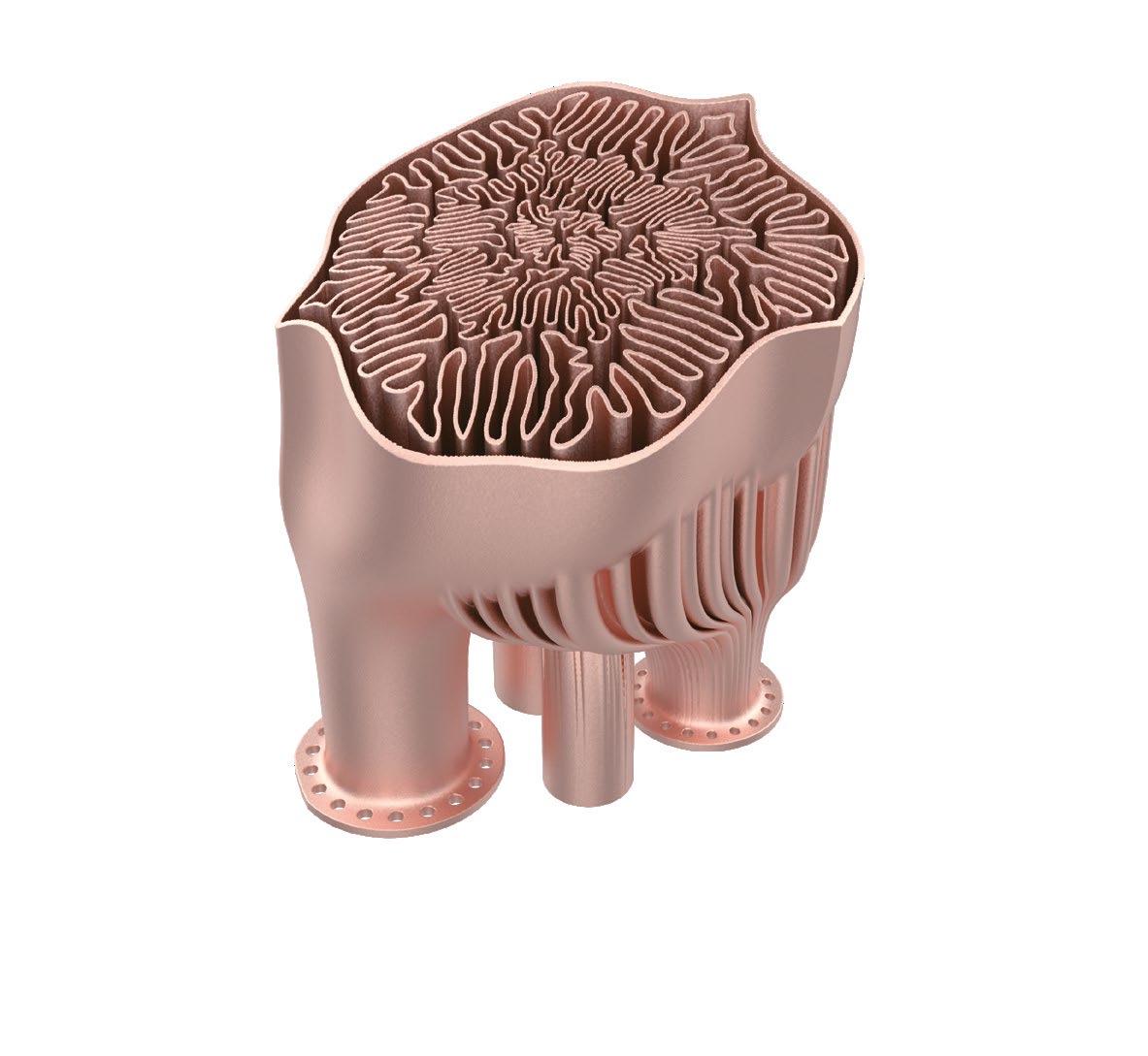

Vol. 8 No. 4 | contents | news | events | advertisers | print sub | e-newsletter | Industry News
UIT-Dresden and Intech collaborate to develop new materials for metal AM
Intech Additive Solutions, Bangalore, India, has collaborated with Umweltund Ingenieurtechnik GmbH Dresden (UIT), a subsidiary of General Atomics Europe/General Atomics (USA), to develop and optimise new materials for metal Additive Manufacturing using AMOptoMet Ultimate version 2.0, Intech’s parameter optimisation software for metal Laser Beam Powder Bed Fusion (PBF-LB).
“AMOptoMet is a parameter optimisation software that provides the right process parameters to achieve better surface finish and desirable mechanical properties in metal 3D printed parts,” stated Sridhar Balaram, CEO & founder of Intech Additive Solutions. “The software helps in printing parts right first time, and reduces the time taken for the Design of Experiments
(DOE) when developing parameters to print new materials. UIT-Dresden’s use of AMOptoMet in their research projects further validates the software and gives us invaluable feedback to incorporate features to address new and emerging applications and materials in metal 3D printing. We look forward to our collaboration with UIT-Dresden.”
The research and development at UIT-Dresden in advanced materials and material characterisation for use in metal AM, along with fundamental multi-physics simulations of the metal AM process – complements the parameter prediction and optimisation capabilities of the AMOptoMet software. Specific projects for deeper collaboration will be identified with definite objectives – to benefit both UIT-Dresden’s research
programmes and the development and validation of Intech’s AMOptoMet software.
“Intech’s AMOptoMet has been of great help in our R&D activities,” commented Dr Horst Maerten, Director for Science and Technology at UITDresden. “Our initial studies indicate that the software can be used by UIT-Dresden as a reference against UIT-Dresden’s theoretical studies and simulation efforts coupled with the test data obtained from experiments on DMG MORI 3D printers at UIT’s affiliates within the General Atomics group of companies. UIT’s research efforts will contribute to the further validation of the AMOptoMet software for specific applications and materials, like superalloys and nano-functionalised alloy powders for advanced AM processing, and provide useful feedback based on our experience of using the software.” www.intechadditive.com www.uit-gmbh.de

Metal Additive Manufacturing | Winter 2022 47 Vol. 8 No. 4 © 2022 Inovar Communications Ltd | contents | news | events | advertisers | print sub | e-newsletter | GETPDF Industry News
Aluminum Alloy Powders for Additive Manufacturing
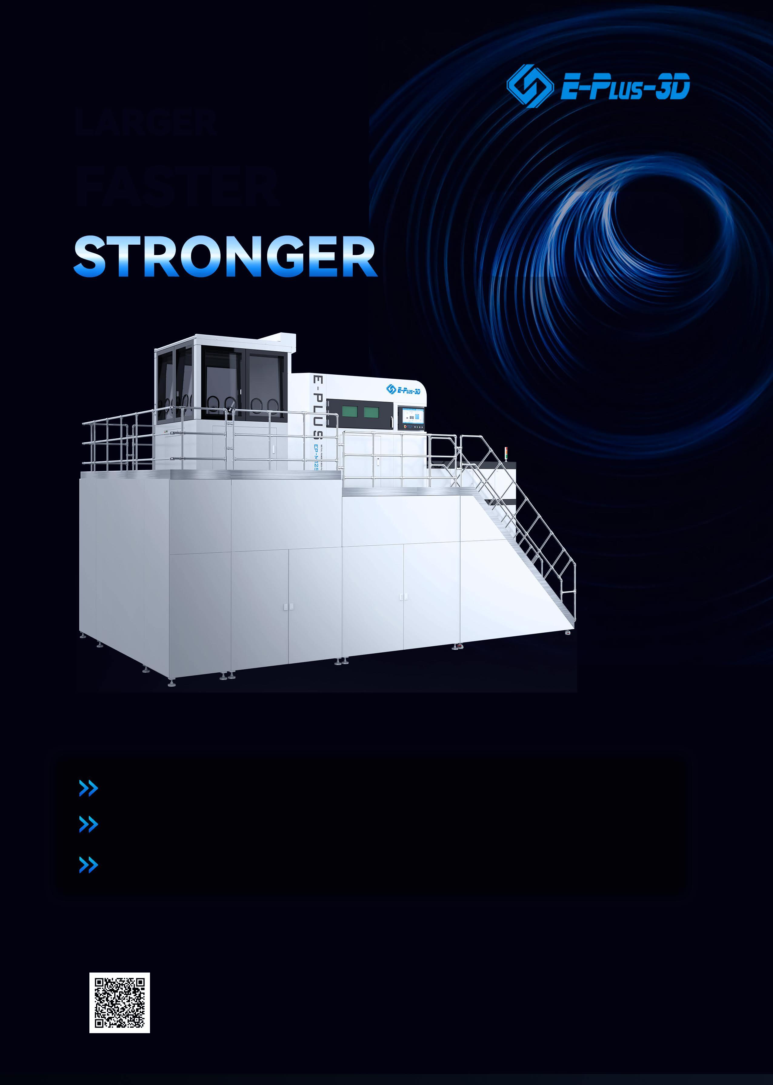

Farsoon expands FS621M line with three large-format AM machines
Farsoon Technologies, headquartered in Changsha, China, has announced three new Laser Beam Powder Bed Fusion (PBF-LB) Additive Manufacturing machines for the AMEA and US markets: the FS621M Pro Platform, consisting of the FS621M Pro-4 & FS621M Pro-6, and the FS621M-U-4. These machines are targeted for the high-speed production of high-quality, large-scale Additive Manufacturing.
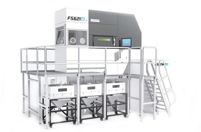
The large-frame FS621M features a build volume of 620 x 620 x 1100 mm. Taking the feedback from the industrial user base and application requirements from aerospace, oil & gas and energy sectors, Farsoon developed the FS621M Pro and FS621M-U-4 machines for larger build volumes and batch production capabilities with materials such as titanium alloys, aluminium alloys, nickel-base superalloys, stainless steels and maraging steels.
The FS621M Pro features a build volume of 620 x 808 x 1200 mm, representing a 30% extension in the Y direction compared to the standard FS621M; it can be equipped with four or six 500 W lasers.
With a build platform size of 620 x 620 mm and a vertical axis of 1.7 m, a 54% increase in the Z height compared to the standard FS621M. The FS621MU-4 features a build volume of 653 l – reputedly one of the largest in the metal laser sintering market – and four 500 W lasers.
The advanced multi-laser scanning strategy enables high calibration accuracy in the overlapping area in an effort to enable uniform mechanical properties and surface finish of the parts throughout the build platform.
In addition, build process control, real-time recording & monitoring capabilities enable good build quality.
The FS621M Pros and FS621M-U-4 can be equipped with a permanent filter module, allowing long-term operation for extremely large builds. The powder handling processes of the two 621M machines share a common powder container design, offering continuous powder feeding to the build and the ability to more easily exchange and monitor powder quality.
Farsoon has announced that it plans on the future release of an FS621M Pro-8 (eight laser) and an FS621M-U-6 (six laser). www.farsoon.com
Norsk Titanium AS, Hønefoss, Norway, has marked its expansion into the industrial manufacturing market with the serial production of an additively manufactured 80 kg Ti-6Al-4V component. This recurring production purchase order comes from Norsk Titanium partner Hittech Group, based in Den Haag, the Netherlands.
Development of the component was completed earlier this year in accordance with industrial material specifications. Production of the components commenced at the Norsk Titanium’s development centre
Farsoon has released two larger iterations of its FS621M AM machine intended for larger build volumes and batch production (Courtesy Farsoon)
in Hønefoss before moving to its Plattsburgh Production Center in New York, USA.
With its proprietary Rapid Plasma Deposition® (RPD®) technology and 700 MT of production capacity, Norsk Titanium offers Additive Manufacturing value-added metal parts to a large addressable market. Parts additively manufactured with RPD are already used on commercial aircraft and the company is said to have gained significant traction with many defence and industrial customers.
“RPD is uniquely suited for this application,” stated Nicholas Mayer,
VP Commercial, Norsk Titanium. “The high deposition and near-net shape part that our process delivers allows our customer to reduce their raw material costs and improve their productivity. This effectively increases their capacity without any capital investment.”
“This is an important milestone for Norsk Titanium,” Mayer continued. “Entry into the industrial market is key to our long-term growth. This production milestone is one of our primary goals for this year, along with expansion of our commercial aerospace customer base and penetration of the US defence market.”
www.norsktitanium.com
Metal Additive Manufacturing | Winter 2022 49 Vol. 8 No. 4 © 2022 Inovar Communications Ltd | contents | news | events | advertisers | print sub | e-newsletter | GETPDF Industry News
Norsk Titanium enters into industrial manufacturing with Hittech order
AddUp and Dassault Aviation aim to automate serial AM in aerospace sector
AddUp, headquartered in Cébazat, France, and Dassault Aviation are collaborating to bring automated metal Additive Manufacturing processes into the aerospace sector. With the aerospace industry facing challenges to maintain and increase its competitiveness, the use of metal Additive Manufacturing, under industrial-scale production conditions, is expected to offer a solution.
It is in this context that the collaborative R&D project Aeroprint, coordinated by Dassault Aviation, was set up, with the help of numerous partners, research centres, universities, and industries, of which AddUp is a part. Structured over five years, this project aims to develop, qualify and implement a competitive pre-industrial demonstrator of multi-material metal AM (Ti and Al), to manufacture complex aeronautical parts certified in classes 2 and 3. The Dassault Aviation site in Argonay in the Auvergne-Rhône-Alpes region of France has been identified as a
pilot for the implementation of this process.
AddUp will be in charge of developing a new production system based on interoperability and robotisation of processes. The automated workshop will allow, thanks to AM, series production as well as multi material part production for aviation. The objective is to pool the equipment while ensuring the separation and proper circulation of the two materials chosen. AddUp’s team is working on a new type of closed enclosure that allows the powder to enter on one side and a tray of metal parts to exit on the other. This future workshop will be composed of two production units of four FormUp® 350 machines based on Laser Beam Powder Bed Fusion (PBF-LB) AM technology, as well as the necessary finishing needs.
After a phase of joint research and development to explore all the project’s requirements, AddUp is now working on the full-size model
Avimetal AM enters Additive Manufacturing machine market
Avimetal AM, a subsidiary of Jingcheng Electromechanical, Beijing, China, has added four new Laser Beam Powder Bed Fusion (PBF-LB) Additive Manufacturing machines to its portfolio: the MT280, MT330, MT450, and the MT650.
The company has reported that the first of these models, a MT280, was recently delivered to a Chinese university, strengthening
the company’s existing relationship with university researchers focussed on AM. The cooperation between the company and the university is expected to enable the research & development of new alloy powders and to boost the AM industry in China.
The MT280 AM machine is aimed at the needs of both scientific research (small batch production) and multi-application fields. The core parameters of the equipment are all open source and compatible with titanium and its alloys, superalloys, aluminium alloys and a variety of refractory metals.
In August of this year, one month before the first successful delivery, the equipment development team conducted strict AM testing on MT280 and successively carried out the
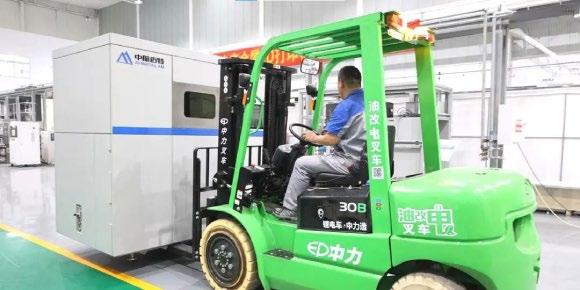
to verify and validate the principles retained, from mechanical design to autonomy. AddUp Manager, equipped with an ultra-fast trajectory generation engine, allows the preparation of production files by accessing more than 250 modifiable variables and customisable fusion strategies. Monitoring, a key issue for such a project, will be carried out using the already available AddUp Dashboards software and enhanced by bricks developed for this purpose.
AddUp Dashboards allows users to view production data in real-time, monitor the shop floor, and quickly analyse machine events. Among the pre-configured views offered in the software is a customisable map that shows real-time progress, remaining production time, and current status. Users can thus access data from a production run made a few months earlier and follow production in progress via the same tool.
Once complete, this precursor automated workshop will be the basis of a ready-to-use industrial solution for the deployment of Additive Manufacturing in existing production facilities.
www.addupsolutions.com
verification of typical materials such as titanium alloys, high-temperature alloys, aluminium alloys and refractory metals. The density of these additively manufactured materials was said to be above 99.9%, and the full-format consistency, build accuracy, mechanical properties and stability between different batches were all reported to meet the needs of users.
Relying on over a decade of material research and development, Avimetal AM has accumulated a solid foundation of knowledge on PBF-LB Additive Manufacturing. Currently, Avimetal AM is putting more machines into production and making deliveries to organisations in both research and industry. In the future, the company hopes to produce a combined material and process database, as well as bringing Additive Manufacturing to a variety of industries.
www.en.avimetal.com
Metal Additive Manufacturing | Winter 2022 50 © 2022 Inovar Communications Ltd Vol. 8 No. 4 | contents | news | events | advertisers | print sub | e-newsletter | Industry News
Avimetal AM has successfully entered into the AM equipment market (Courtesy Avimetal AM)
● GAS OR ULTRASONIC ATOMIZATION FOR SPHERICAL POWDERS WITHOUT ANY SATELLITES
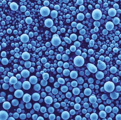
Ideal for LPBF, MIM and other Additive Manufacturing applications with the need for high quality powders with high purity, sphericity and wide range of reproducible particle size distribution.

● WATER ATOMIZATION FOR MORE IRREGULAR POWDERS Ideal for recycling/refining process, press & sinter process and others.
● MAXIMUM PURITY BY OXIDATION-FREE PROCESSING in the closed-chamber machine by means of de-gassing, vacuum and protective gas features
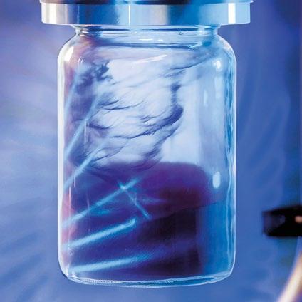
● FOR A WIDE RANGE OF METALS AND FOR SMALL TO MEDIUM AMOUNTS AUG series HTC+ gas atomizers with temp. max. up to 2100° C Also versions for high-reactive metals as aluminium or magnesium available!
● AIR CLASSIFIER AC SERIES FOR PRECISE SEPARATION OF METAL POWDERS into fine and coarse powder fractions especially in the range < 25 µm, where conventional sieving operations fail.
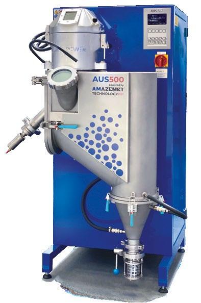
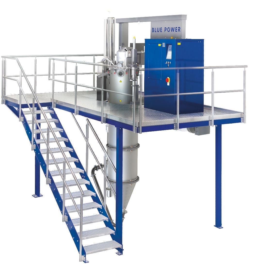
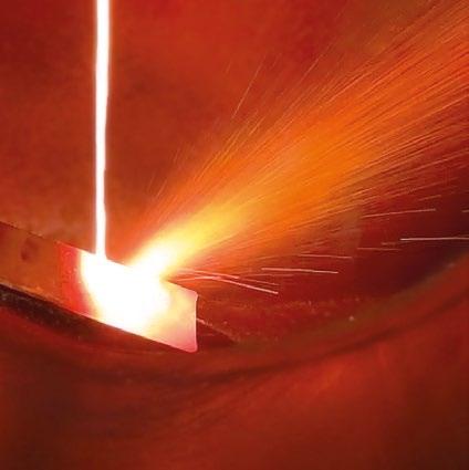
● ALL UNITS DESIGNED FOR EASY HANDLING AND CLEANING, QUICK ALLOY CHANGE WITH MINIMUM CROSS CONTAMINATION
www.bluepower-casting.com
POWDER ATOMIZATION PLANTS · AIR CLASSIFIERS · VACUUM PRESSURE CASTING SYSTEMS CONTINUOUS CASTING SYSTEMS · MELTING MACHINES · GRANULATION SYSTEMS 75045 Walzbachtal · Germany · Phone +49 7203 9218-0 · E-mail: info@bluepower-casting.com
DIFFERENT ATOMIZATION AND SEPARATION TECHNOLOGIES TO MEET YOUR NEEDS:
Inert gas air classification on AC 1000 G Ultrasonic atomization
Gas atomized Ag-based solder alloy powder Gas Atomization Unit AUG 3000 BLUE POWER EQUIPMENT & EXPERTISE FOR YOUR METAL POWDER PRODUCTION
Ultrasonic
Atomizer
AUS 500 powered by AMAZEMET
PyroGenesis passes annual metal powder quality audits
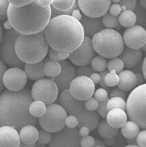
PyroGenesis Canada, Inc., Montreal, Québec, Canada, has announced that it has passed its annual quality audit for two key international standards: ISO 9001:2015 and AS9100D, the latter being a quality management specific to the aerospace industry. The audits encompassed all of PyroGenesis’ facilities for the purpose of meeting compliance with the existing quality management designations. The company reported zero NonConformances Reports (NCR) and, as a result of this audit, PyroGenesis’ newest facility located in LaSalle, Quebec, was officially added to the ISO 9001:2015 certification.
“I would like to thank all those who participated in this audit, not only for their support, effort, and teamwork, but also for their continued adherence to maintaining the company’s high standards
as process owners of the quality system,” commented P Peter Pascali, CEO and chair of PyroGenesis. “Along with a superior product, a robust and efficient value-added Quality Management System is essential to meeting our objective of becoming a globally competitive company in the Additive Manufacturing and 3D printing sector. This is even more important given the backdrop of recent developments where potential clients complete their own audit process with the goal to qualifying PyroGenesis as a powder supplier.”
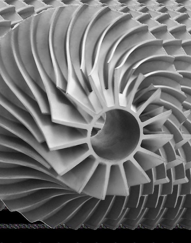
In addition to its current qualifications, PyroGenesis aims to become ISO 13485:2016 certified, a Quality Management System designation required by most manufacturers within the medical devices and related services industry. Once obtained, the company’s metal powder offerings
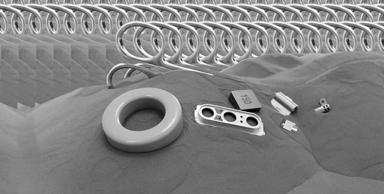
will be available to medical device makers as well.
The company has also announced an update regarding the completed in-house audit of its NexGen powder production facility by a global aerospace company. As part of the audit, the aerospace company suggested modifications and adjustments in order to proceed with the delivery of final samples of titanium powder for chemical and mechanical testing. PyroGenesis states that it has met over 90% of the suggestions and is working on completing the remaining 10% before the end of the year.
Massimo Dattilo, VP, PyroGenesis Additive, stated, “Validating our process, our system, and ultimately our product, to the most stringent and challenging standards has been critical to our strategy to produce the highest quality titanium metal powders. We continue to be on track for a Q4 2022/Q1 2023 target for final submission and approval.” www.pyrogenesis.com
Metal Additive Manufacturing | Winter 2022 © 2022 Inovar Communications Ltd Vol. 8 No. 4 | contents | news | events | advertisers | print sub | e-newsletter | Industry News
Oqton partners with DigiFabster for an AM e-commerce solution
Oqton, Ghent, Belgium, has entered into a partnership with Software as a Service (SaaS) provider DigiFabster, headquartered in Pasadena, California, USA, to deliver an e-commerce solution combining Oqton’s manufacturing operating capabilities with DigiFabster’s instant quoting, e-commerce interface and billing functions. The partnership is hoped to lead to a complete solution to help manufacturers automate their entire production workflow, including additive and subtractive technologies.
Precision-engineered parts are often expensive to manufacture and purchase. As a result, these parts are not often kept in inventory, but are produced on demand when needed. Companies frequently have strict requirements, including obtaining multiple quotes for review and approval – along with balancing the lowest possible price and shortest lead times with high production standards. The manufacturers of these parts are then expected to manage their production capacities with complex intertwined dynamics, including accounting for material management and machine time, factoring in experts’ working hours to run the systems, and certifications for defined quality-assurance schemas. The partnership between Oqton and DigiFabster overcomes all of these challenges by delivering an integrated, purpose-built order, payment, and production automation solution for manufacturers, and a convenient purchasing experience for buyers.
“E-commerce continues to be a disruptive force — transforming consumer behaviour and our expectations for easyto-use services,” stated Dr Ben Schrauwen, SVP & General Manager, Oqton. “We saw a real opportunity to bring together
Oqton’s advanced manufacturing capabilities with DigiFabster’s e-commerce solution to transform the entire process. Through the combination of a convenient, modern front end experience with streamlined back end processes such as digital inventory management, and automated fulfilment and logistics, we’ve automated the entire production workflow to
provide a more efficient experience for manufacturers and purchasers.”


DigiFabster is a complete e-commerce and quoting automation solution that is designed for quick custom implementation and ease of use. The insights gained from this process are hoped to offer customers to make reliable predictions and measurable optimisation. Manufacturers who make use of this solution can be up and running within a few hours. www.oqton.com www.digifabster.com
Metal Additive Manufacturing | Winter 2022 53 Vol. 8 No. 4 © 2022 Inovar Communications Ltd | contents | news | events | advertisers | print sub | e-newsletter | GETPDF Industry News
PERFECT HEAT
ADDITIVE
TAV VACUUM FURNACES SPA Via dell’Industria, 11 - 24043 Caravaggio (BG) - ITALY ph. +39 0363 355711 - info@tav-vacuumfurnaces.com www.tav-vacuumfurnaces.com
standard
customized VACUUM
for INDUSTRY
R&D
Vacuum thermal
- DEBINDING & SINTERING - SOLUTION TREATMENT - STRESS RELIEVING
BINDER JETTING, DMLS, SLS, SLM, WFMD
2
H2
THE
TREATMENT SOLUTION FOR
MANUFACTURED PARTS
Wide range of
and
FURNACES
and
LABORATORIES.
processes:
Used in the most AM technologies:
Process gas: Ar, N
,
Vacuum level: from atmosphere to 10-6 mbar Temperature range: up to 2300 °C METAL or GRAPHITE chamber
Orbex secures over £40M in Series C funding
Spaceflight company Orbex, headquartered in Forres, Scotland, UK, has secured £40.4 million for its Series C funding round, led by new investor the Scottish National Investment Bank. The new round of funding is anticipated to allow the company to scale up its resources as it counts down to the first vertical launch in the UK, as well as unlocking additional funding for future projects.
Orbex recently revealed the final form of its Prime rocket, a 19 m long, two-stage rocket designed to transport small satellites (up to 180 kg) into low-Earth orbit. The rocket features additively manufactured critical parts built in single pieces, eliminating weaknesses which can arise from welding.
The Prime rocket will launch from the Space Hub Sutherland spaceport near Tongue, on the North coast of mainland Scotland, which is expected to be the UK’s first operational spaceport. Orbex applied for a space launch licence from the UK’s Civil Aviation Authority in early 2022.
This latest funding round saw a renewed commitment from existing investors BGF, Heartcore Capital,
COMPLETE
SOLUTIONS
High-Tech Gründerfonds, and Octopus Ventures. New investors include:
• The Scottish National Investment Bank
• Jacobs, a provider of professional services including consulting, technical, scientific and project delivery for the government and private sector. Jacobs is NASA’s largest service provider, delivering solutions and lifecycle aerospace capabilities
• The Danish Green Future Fund, a special investment fund designed to support the transition to green solutions locally and globally through sustainable technology
• Verve Ventures, a network- and technology-driven venture capital firm headquartered in Switzerland
• British entrepreneurs Phillip and James Chambers, founders of Peakon and Hazport respectively
The Prime rocket is anticipated to be the first orbital rocket to be powered by a renewable bio-fuel – Calor’s Futuria Liquid Gas, a form of bio-propane which may play a part in reducing the carbon footprint of space launches by up to 96% when compared with similarly-sized launch vehicles powered by fossil fuels. The sustainability credentials extend to the company’s ‘home’ spaceport of Space Hub Sutherland, which aims to become the world’s first carbon-neutral spaceport.
Orbex is currently performing a wide variety of integration tests, including the testing of the main propellant tanks and engines, as well as testing launch procedures including rollout, strongback erection, and fuelling procedures in advance of the first launch, which will carry a payload developed by Surrey Satellite Technology Limited, reputedly one of the world’s largest small satellite developers.
“We’re delighted to have closed this new funding round led by the Scottish National Investment Bank,” stated Chris Larmour, CEO, Orbex. “Orbex has made significant progress to get to this point, with the invention of ground-breaking, innovative technology, the rapid development and testing of the launch vehicle, the expansion of our manufacturing footprint in the UK and Denmark, the creation of the UK´s first orbital spaceport in mainland Scotland, and the growth in customers from the UK, Europe and America signing up to launch dedicated payloads with Orbex.”
Larmour concluded, “These results have only been made possible by the maturity and dedication of the entire Orbex team, who bring a huge amount of skill and experience to their tasks from a wide variety of industries, launch systems, and spacecraft. This significant new funding round is testament to the work of that team and will allow us to continue to build Orbex towards our long-term goal of establishing a reliable, economically successful, and environmentally sustainable European space launch business.”
www.orbex.space
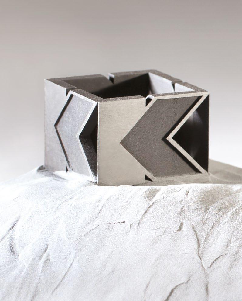
Metal Additive Manufacturing | Winter 2022 54 © 2022 Inovar Communications Ltd Vol. 8 No. 4 | contents | news | events | advertisers | print sub | e-newsletter | Industry News www.kennametal.com/am
Kennametal brings deep expertise to every layer of the AM process — from powder to finished part — unlocking the full value of 3D printing for demanding wear, erosion, corrosion and high-temperature applications.
|
|
ADDITIVE
METAL POWDERS
PRINTED COMPONENTS
SERIES PRODUCTION
Unique inert gas atomizing technology produces highly specified, spherical metal powders for MIM and AM applications. Team with history of developing and producing fine gas atomized powders since 1990.


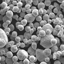
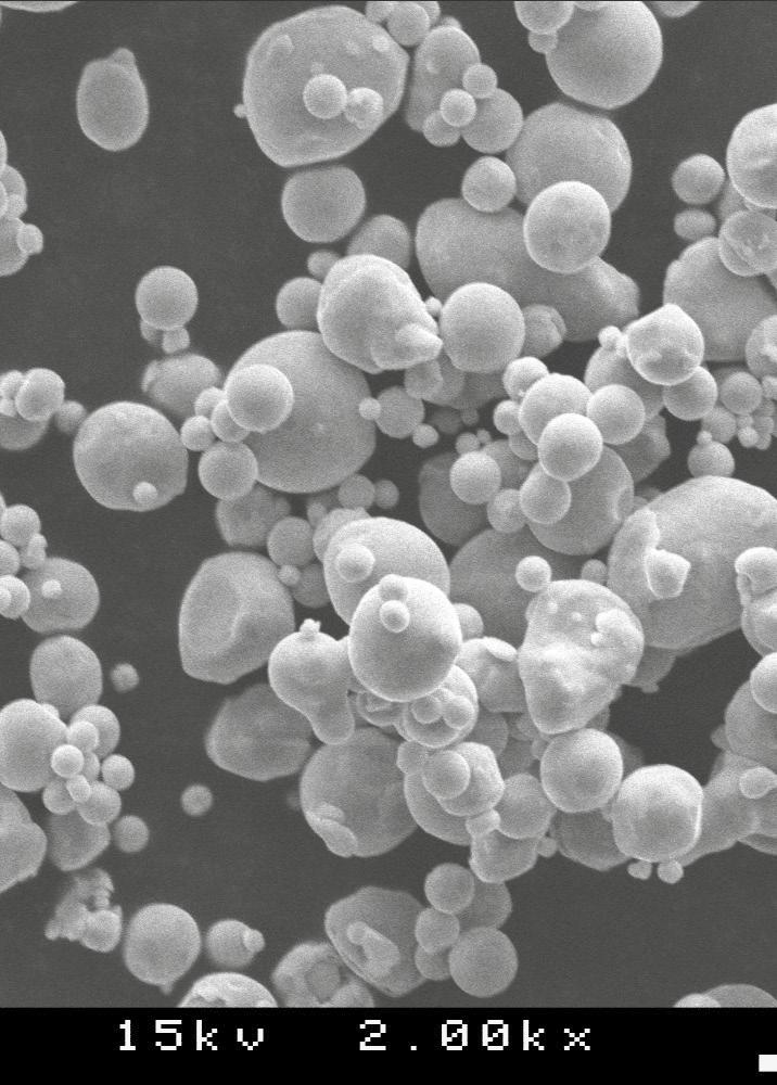
Specializing in sub 30 micron powders, Ultra Fine has the technical capability to work with you to develop and produce the powder to suit your application. Ultra Fine offers flexibility and quick turn-around times.
With partner Novamet Specialty Products Corp., Ultra Fine provides various after treatments, coatings and other capabilities using Ultra Fine’s high quality powders.

500 Park East Drive | Woonsocket, RI 02895 USA 1420 Toshiba Drive, Suite E Lebanon, TN 37087 USA www.novametcorp.com MIM & BINDER-JET AM METAL AS9100:2016 CERTIFIED POWDERS
Providing Quality Metal Powders Since 1976 ww finepowder.com ISO9001:2015 CERTIFIED ISO9001:2015CERTIFIED
More companies join ColdMetalFusion Alliance as turnkey JobShop and LabSystem solutions announced
The ColdMetalFusion Alliance has announced that a number of companies have now joined, offering a range of services to users of the technology. The alliance also announced two turnkey solutions are now available for those looking to establish either an Additive Manufacturing production line or bring AM product development and small-series production in-house.
The ColdMetalFusion Alliance is a consortium of companies with experience in the fields of sintering, Additive Manufacturing, and tradditional industrial manufacturing. Together, the alliance’s members provide services, equipment, material, software, and expertise to customers in the metal manufacturing industry.
The ColdMetalFusion process is built around well-established and robust technologies, including polymer-based Laser Beam Powder Bed Fusion (PBF-LB/P), solvent debinding, sintering and postprocessing. By integrating metal powder into a highly functional binder system, all metals used in Powder Metallurgy are available. The part is additively manufactured at low temperature (< 80°C) on standard PBF-LB/P machines, melting just the plastic-binder. No support structures are necessary in the build process itself, which also enables the parts to be placed freely in the build box. After a de-powdering stage, the high strength of the bound green part enables mechanical post
processing, such as turning, milling, etc, before the sintering stage. The final steps follow the MIM process, with a debinding and sintering stage resulting in the final part.
Members of the ColdMetalFusion Alliance contribute on the specifications of their area of expertise, to increase the overall quality for all users. Including those joining over the last few months, the list of members now includes:
• Lömi
• MIMplus
• element 22
• headmade materials
• Bernstein
• Miba
• Pres-X
• Farsoon Technologies AM Solutions Carbolite Gero Nippon Gases
• Sintratec
JobShop and LabSystem
Both the CMF JobShop and CMF LabSystem include the necessary machines to produce additively manufactured components from a wide range of metals.
The CMF JobShop is aimed at production centres and machine shops. The solution is compatible with 316L Stainless, Ti-6Al-4V grade 5, 17-4 PH stainless and M2 tool steel. The JobShop consists of:
• HT252P production-level Laser Beam Powder Bed Fusion
machine from Farsoon, with a 60 W CO 2 laser in a 250 x 250 x 320 mm build envelope.
• A fully automated, closed-loop 50 litre debinding station from Lömi, featuring an integrated solvent debinding, drying and solvent recycling station. It is optimised for CMF binder-component extraction with solvent
• A high-temperature sintering furnace optimised for ColdMetalFusion from Carbolite Gero. The chamber measures 240 x 240 x 400 mm, operates at a maximum temperature of 1600°C and enables 100% hydrogen processing
The CMF LabSystem is intended for fast application and process development. This solution is compatible with 17-4 PH stainless, M2 tool steel, H13 tool steel and Inconel 625. The LabSystem consists of:
• Sintratec S2 modular PBF-LB machine from Sintratec, with a cylindrical build space of 160 mm (diameter) x 400 mm. The starter cell can be expanded as needed and includes a material handling station for depowdering.
• A 30 litre debinding machine from Lömi features an integrated solvent debinding and solvent recycling station.
• Tube sintering furnace optimised for ColdMetalFusion from Carbolite Gero. The furnace has two heating zones and is equipped with additional heat shielding. The tube measures 300 mm x 180 mm (diameter) and operates at a maximum temperature of 1300°C
www.coldmetalfusion.am
Metal Additive Manufacturing | Winter 2022 56 © 2022 Inovar Communications Ltd Vol. 8 No. 4 | contents | news | events | advertisers | print sub | e-newsletter | Industry News
Powder Removal & Cleaning
SLS Additive Manufacturing Green Part Processing Solvent Debinding Sintering Finishing
The ColdMetalFusion process is built around well-established and robust technologies. The resulting parts share the properties of those manufactured by Metal Injection Moulding (Courtesy ColdMetalFusion Alliance)


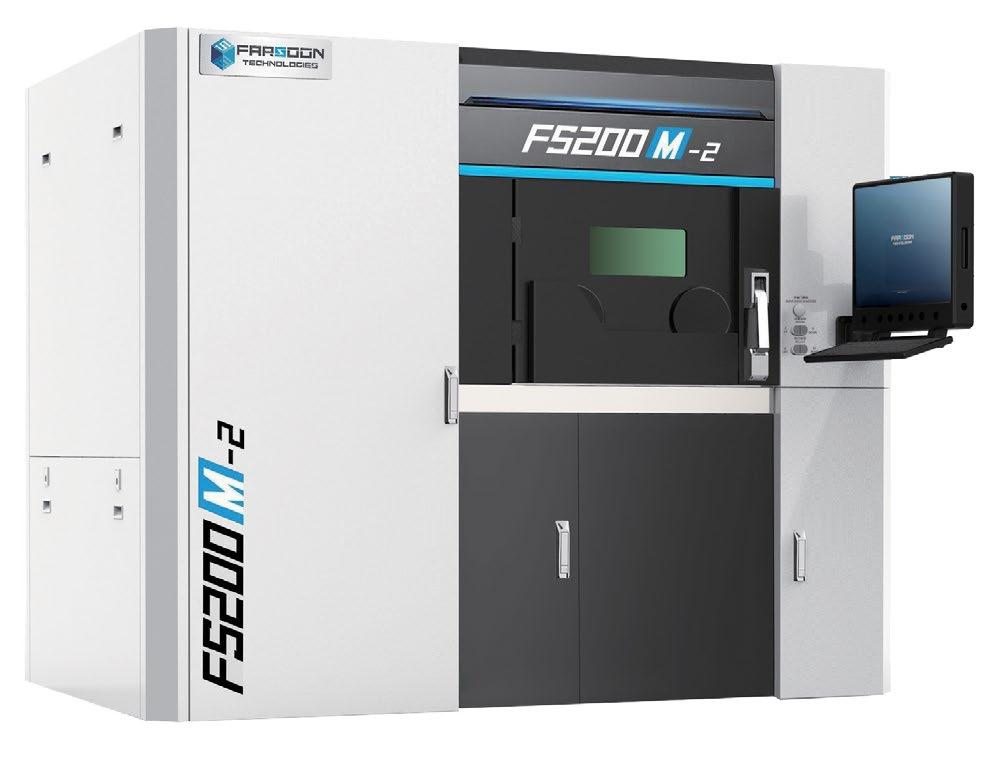
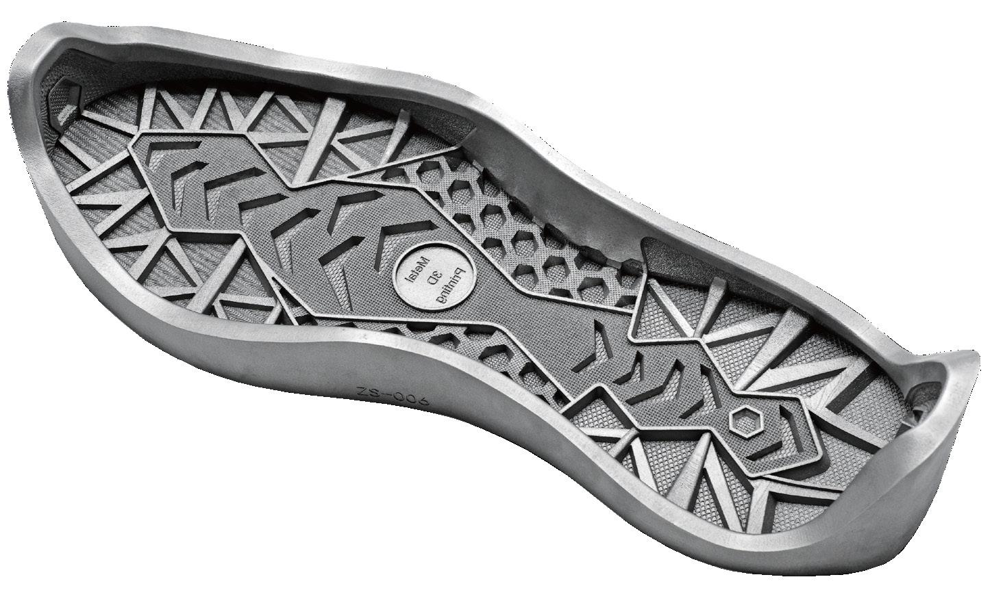
A High-value Proposition Metal System ready for Series Production. FS200M-2 Metal Laser Powderbed Fusion Technology www.farsoon-gl.com Learn your full benefits, contact us: globalinfo@farsoon.com Booth 2224 May 2-4, 2023 Chicago, IL Booth P18 Mar 19-23, 2023 Hilton Chicago Metal • 425×230×300mm envelope • 2×500-watt fiber lasers • Reduced manufacturing cost • Fast machine turn-over • Ease of operation Shoe Mold System: FS200-2 Material: 316L
Liberty Powder Metals improves metal AM powder yield
Liberty Powder Metals (LPM), part of GFG Alliance’s Liberty Steel Group, has identified a process configuration which increases the yield for atomised Additive Manufacturing powders.
The DANDY 2 project, funded by Innovate UK, successfully linked the modelling of the atomisation process via computation fluid dynamics (CFD) and experimental modelling (EM) with the plant operations to increase the yield of Additive Manufacturing powders, with a particle size distribution of 15-45 μm, by over 40% via an iterative design optimisation of the step change liquid atomiser nozzle and powder production process changes. This involved collaborative R&D with the Materials Processing Institute, Middlesborough, North Yorkshire, UK.
During the year-long project, the CFD simulated gas flows, orifice plate, new nozzle designs, gas input temperature link to atomisation velocity, gas input pressure link to aspiration pressure (cross-validated by plant measurement), gasket thickness changed both atomisation velocity and aspiration pressure. EM provided confidence in machine security, enabled further modelling on gasket thickness and changes in nozzle design. CFD combined with the EM on nozzle design development, including high-speed videoing at 115,000 frames per second, providing cross-validation between model flows and against nozzle performance.
LPM completed 193 atomiser melts of 316L and Alloy718, with
individual trials on nozzle design and material, orifice plate, gasket thickness, gas input temperature, gas input pressure (both dynamic and steady state). Each parameter has influenced Additive Manufacturing, which, when combined, have produced a cumulative AM yield increase to 57%. Machine learning tools were applied to this dataset by Swansea University and Materials Processing Institute independently and whilst the dataset was small in terms of ‘big data’, these tools have confirmed the findings from the plant trials and identified various parameters to investigate further.
Powder from twenty-four melts were fully characterised to assess flowability and morphological characteristics. These powders were also used to build mechanical test specimens by Additive Manufacturing. It was found that the powder from the high-yield trials was good quality, easy to manufacture with and provided good mechanical properties.
From the modelling, plant trials, machine learning and powder characterisation, a new configuration was identified to increase the yield for LPM AM powder production.
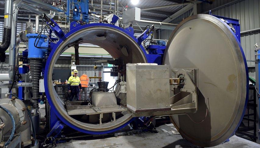
The project, funded by Innovate UK, also examined the use of audiometry and vibration monitoring tools on the atomiser to give real-time feedback and control. LPM intends to continue development of this technology.
www.libertysteelgroup.com www.mpiuk.com
Matexcel expands range of Co-base metal powders
Materials service provider Matexcel, Bohemia, New York, USA, has extended its range of cobalt-based metal powder products. The company now offers multi-functional Co alloys ranging from fine powders to nanostructured materials.
Cobalt-base alloys are commonly known as high wear-resistant materials and often used for dental
restoration and orthopaedic implants. Typically Co alloys have an FCC crystal structure and contain alloying elements like Cr, Ni, Mo and N. Cobalt alloys typically have a higher carbon content than implantable stainless steels, which can lead to the formation of carbides distributed by the material and encourages an improvement in adhesive wear
resistance. Co alloys have superior corrosion resistance compared to stainless steel, which is combined with its high wear resistance. The Co alloy powders now available from Metaxcel include:
• MET-0023 (Co-base CoCrW)
• MET-0024 (Co-base CoCrMo)
MET-0025 (Co-base CoCrMoW)
MET-0026 (Co-base GH5188)
MET-0027 (Co-base GH5605)
• MET-0028 (Co-base GH5941) www.matexcel.com
Metal Additive Manufacturing | Winter 2022 58 © 2022 Inovar Communications Ltd Vol. 8 No. 4 | contents | news | events | advertisers | print sub | e-newsletter | Industry News
Liberty Powder Metals’ Atomiser Plant in Teesside, UK (Courtesy Liberty Powder Metals)


Relativity Space announces 4th generation of its Stargate metal AM platform
Relativity Space, Long Beach, California, USA, has announced the latest iteration of its Stargate 4 th Generation metal Additive Manufacturing machines, the company’s proprietary wire-based Directed Energy Deposition (DED) platform. These AM machines support the development and rate production of Terran R, Relativity’s additively manufactured rocket capable of launching 20,000 kg to low-Earth orbit.
According to Relativity, its latest Stargate AM machine technology defies conventional AM constraints by moving horizontally as it feeds multiple wires into a single build head to additively manufacture orbital rockets. The company is developing customised software and machine learning techniques to allow these AM machines to produce more complex and significantly larger metal products, with improved build speed and reliability. Stargate 4 th Generation AM machines are also stated to simplify manufacturing supply chains, as they are capable of additively manufacturing a rocket with 100 times fewer parts in a matter of months.
The Stargate 4 th Generation AM machines will serve as the primary manufacturing infrastructure for Terran
R production. In the longer term, Stargate 4 th Generation AM machines offer the potential for other end-product use cases within the aerospace, aviation, energy, and defence industries. To date, Relativity has secured five customers across $1.2 billion in customer contracts for Terran R, including a multi-launch agreement with OneWeb and a commercial mission to Mars with Impulse Space.
“Large-scale products that are designed to fly will inevitably be 3D printed,” stated Tim Ellis, cofounder and CEO of Relativity Space. “The lighter a product is, the better it performs, and when 3D printing that product, it’s also faster and more cost-effective to produce with each successive improvement. The compounding rate of progress is high, and we are still in the early days of what printing can achieve.”
“We see 3D printing as an automation technology that has the power to change the pace of innovation in manufacturing, which is why we’ve invested in building our own proprietary tech stack from day one,” Ellis commented. “Stargate printers are designed to unlock rapid iteration, which opens up opportunities for innovation in large-scale manufacturing products. What would take traditional aerospace and space manufacturers years to develop and build, will be reduced down to months due to a highly adaptable, scalable, and automated process, made possible through software-driven manufacturing.”
THERMAL PROCESSING SYSTEMS
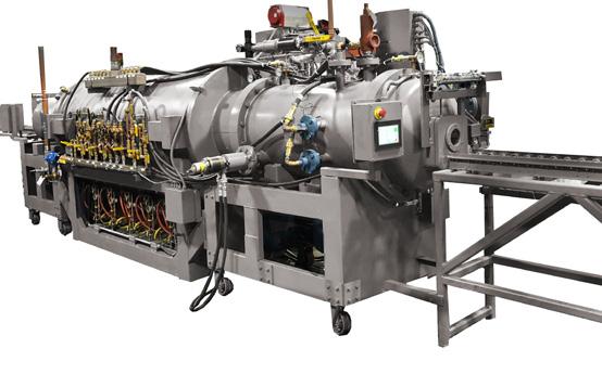
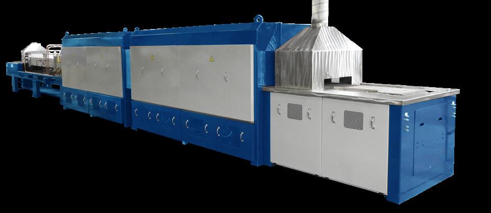
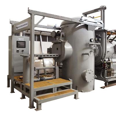
The majority of Terran R components will be additively manufactured inside Relativity’s new headquarters in Long Beach, named The Wormhole. Aeon R engines, for Terran R, will continue to be produced at the company’s other Long Beach factory, The Portal. The Wormhole, a former Boeing C-17 manufacturing plant, was secured by Relativity as its new headquarters in 2021.
Currently 33% operational, the factory has several Stargate 4 th Generation AM machines online with more than a dozen AM machines planned to be producing Terran R components in the coming months. At the full capacity forecasted run rate, each Stargate 4 th Generation AM machine is capable of producing 4 Terran R rockets per year. The remainder of The Wormhole will continue to be built out in phases, bringing more AM machines online and moving more teams into the company’s headquarters as production for Terran R scales.
Scott Van Vliet, SVP of Software Engineering, added, “Iteration empowers innovation not only in our rocket design, but also in our own Stargate printers. In its short history, Relativity has made great strides in evolving its core 3D printing technology, but Stargate 4 th Generation printers are our most innovative leap yet. We’re fundamentally changing the way our factories are designed and operating, and by flipping the script and going horizontal, we’re radically increasing our capacity for scale. Being a software-driven manufacturing company allows us to achieve unique product features, such as integrated pad-ups and domes, with radical flexibility.”
www.relativityspace.com
Metal Additive Manufacturing | Winter 2022 60 © 2022 Inovar Communications Ltd Vol. 8 No. 4 | contents | news | events | advertisers | print sub | e-newsletter | Industry News www.gasbarre.com
PILOT, SMALL, OR HIGH VOLUME PRODUCTION, GASBARRE HAS THE EXPERTISE AND EQUIPMENT FOR EACH APPLICATION
Nanoscale Additive Manufacturing offers structural protection for satellites, drones, and microelectronics
Researchers from Stanford University, California, USA, have designed a new metal/polymer composite for nanoscale Additive Manufacturing capable of absorbing twice the energy of materials with a similar density. This composite could be used to create lightweight, protective lattices for parts with fragile geometries, such as small pieces of satellites and drones, or microelectronics.
“There’s a lot of interest right now in designing different types of 3D structures for mechanical performance,” stated Wendy Gu, an assistant professor of mechanical engineering and a corresponding author on the paper. “What we’ve done on top of that is develop a material that is really good at resisting forces, so it’s not just the 3D structure, but also the material that provides very good protection.”
To design a better material for Additive Manufacturing, Gu and her fellow researchers incorporated metal nanoclusters into their feedstock. The researchers are manufacturing via two-photon lithography AM, where the feedstock is hardened through a chemical reaction initiated by laser light. Research found that the nanoclusters jump-started this hardening, resulting in a polymer/metal composite.
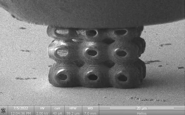
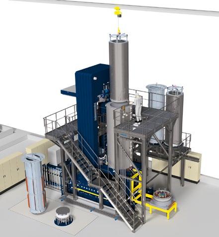
“The nanoclusters have very good properties for taking in the laser light, and then converting that to a chemical reaction,” Gu added. “And they’re able to do this with several classes of polymers, so they’re even more versatile than I expected.”
The researchers combined these metal nanoclusters with commonly used AM polymers, including acrylates, epoxies, and proteins. The nanoclusters also helped speed up the build process; by combining the nanoclusters with proteins, for example, the Stanford researchers were able to additively manufacture at a rate of 100 mm per second, about 100 times faster than had previously been achieved in nanoscale protein Additive Manufacturing.
The researchers tested their new composite with several different lattice structures, prioritising the ability to carry a heavy load in some, and the ability to absorb an impact in others. With the metal/polymer composite, all the structures reportedly demonstrated a good combination of energy absorption, strength, and recoverability.
Gu concluded, “The lattice structure certainly matters, but what we’re showing here is that if the material it’s made out of is optimised, that’s more important for performance. You don’t have to worry about exactly what the 3D structure is if you have the right materials to print with.”
The paper, ‘Mechanical nanolattices printed using nanocluster-based photoresists’, was published in Science
www.science.org www.stanford.edu
Metal Additive Manufacturing | Winter 2022 62 © 2022 Inovar Communications Ltd Vol. 8 No. 4 | contents | news | events | advertisers | print sub | e-newsletter | Industry News •Cold Isostatic Press (CIP) •Hot Isostatic Press (HIP) • Warm Isostatic Press (WIP) •Hyperbaric simulators ENGINEERED PRESSURE SYSTEMS INTERNATIONAL NV Industriezone TTS – zone Waas 2608 Walgoedstraat 19, 9140 Temse – Belgium T: +32 (0) 3 711 24 64 E: info@epsi.be https://epsi-highpressure com/ Your partner for all High-Pressure solutions
Image taken from a video showing the in-situ SEM compression of a nanocluster-polymer SP nanolattice (Courtesy Science)
SUBCONTRACTING FINISHING SERVICES

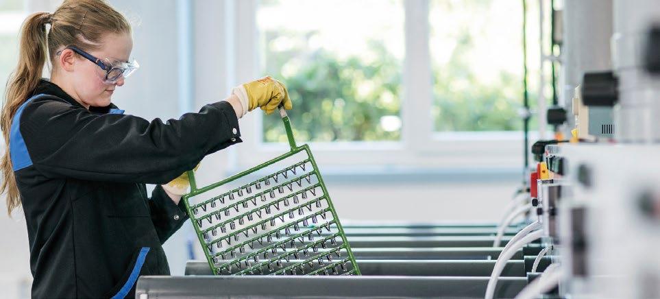
RENA Technologies offers Hirtisation® for any number of parts also as a finishing service at our site in Austria. We value every customer and are able to adjust to any specific application task. We welcome all lot sizes from single parts to large production series. As certified finishing center, processes and services follow the strict ISO9001/14001 regulations. In addition to the finishing service we, as Austria’s largest post-processing lab, offer a broad range of Quality Control testing.
HIRTISATION®
Optimum results may require adjustments of the printing process to the consecutive post processing! rena.com
THE POWER OF dynamic (Electro-)chemistry
Dyndrite and Novanta collaborate on software for laser-based metal AM
Dyndrite, headquartered in Seattle, Washington, USA, has announced a collaboration with Novanta Corporation, headquartered in Bedford, Massachusetts, USA, in support of the company’s Firefly 3D and Lightning™ II laser beam steering solutions. The companies will collaborate on a proof-of-concept that will allow Dyndrite software to
directly generate low-level scanning trajectories for Novanta hardware. This provides users of Dyndrite Additive CAM software the ability to generate very fine-resolution scanner trajectories, making full use of the advanced functions and underlying power of the laser scanner hardware. Novanta’s high-precision scanning solutions, used in a wide variety
of Laser Beam Powder Bed Fusion (PBF-LB) AM machines, are often not fully utilised by standard trajectory strategies. Novanta scanning solutions are capable of being operated at much higher levels of performance with a wider range of scan strategies than are often made available to the current open market.
Engineered as an enclosed, compact solution to enable multiheaded machine architectures with up to 100% overlap, Firefly 3D is reported to be the ideal solution for today’s serial production high-throughput AM machines. Incorporated within the design are features to simplify installation and operation including features such as precise monitoring of the AM process and synchronised process and motion data.
“High-performance scanners such as Novanta’s Firefly 3D and Lightning™ II are designed with smart technology to predict their own capabilities and limits,” stated Simon Matthias, Technical Business Development Manager, Novanta. “This informs the controlling hardware how best they can be driven to allow full use of the scanners’ complete bandwidth. We’ve seen what is possible from a materials and process standpoint with Dyndrite and knew working with them would unlock the full potential of our scanners.”
Dyndrite explains that parameter and scanning pattern development is a significant undertaking when qualifying new materials and machines. For this reason, often there is a conservatism that leads users and developers of machines, and the software that drives them, to stay within traditional approaches, relying on standardised scanning patterns such as a checkerboard or similar hatch-based approaches. The result is often a reduction in efficiency and the missed potential of realising improvements in material microstructures.
The company aims to disrupt this traditional model of parameter development by providing innovative software power, freedom and control over the scanner.
www.dyndrite.com

Metal Additive Manufacturing | Winter 2022 64 © 2022 Inovar Communications Ltd Vol. 8 No. 4 | contents | news | events | advertisers | print sub | e-newsletter | MAM Island Half Page Ad – Grow Profits – C Series.indd 1 11/27/21 6:13 PM Industry News
SPEE3D reports successful hot fire test of rocket engine prototype
SPEE3D, headquartered in Melbourne, Australia, successfully conducted the first hot fire test of a prototype rocket engine at a test site in Darwin, Australia, in September 2022. The testing occurred as part of the government-backed SPACE3D project, which aims to help support the country’s space industry as a whole, as well as the economy and job market of Australia’s Northern Territory.
SPEE3D’s laboratory prototype is the first of a series of rocket engines and components to be designed, manufactured, and tested over the next eighteen months. It was designed to utilise the company’s Cold Spray Additive Manufacturing technologies, as well as other new manufacturing processes that collectively aim to deliver reusable rocket engines within lead times
and costs significantly lower than traditional technologies.
“SPEE3D’s Cold Spray technology facilitates new ways to design and manufacture demanding space components potentially more rapidly and at a lower cost than incumbent technologies,” stated Gary Owen, Chief Space Officer for SPEE3D. “Our design, manufacturing, and test expertise, once proven by events such as successful rocket engine hot fire tests, will position us well to play an important role in the rapidly expanding space industry.”
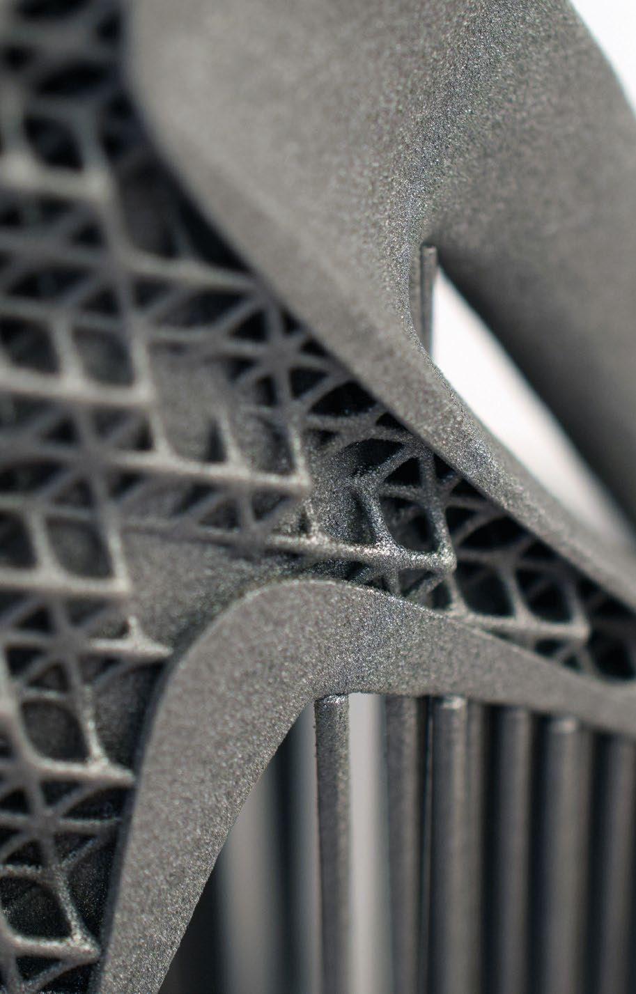
In 2021, the SPACE3D project received $1.25 million in grant funding from the Australian Federal Government’s Modern Manufacturing Initiative, with an additional $312,000 from the Northern Territory Government. Since beginning the project the team have also received
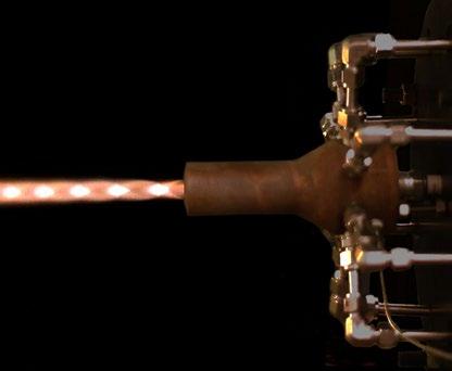
A filtered composite image of the first hot fire test taken using a high-speed camera; 500 frames per second (Courtesy SPEE3D)
in-kind support from Charles Darwin University and RMIT University.
Nicole Manison, Australia’s Minister for Advanced Manufacturing, added “We are thrilled the SPACE3D programme is helping to revolutionise the space industry in Australia, and this successful test symbolises a significant step forward.” www.spee3d.com
Metal Additive Manufacturing | Winter 2022 65 Vol. 8 No. 4 © 2022 Inovar Communications Ltd | contents | news | events | advertisers | print sub | e-newsletter | GETPDF ALUMINIUM ALLOYS FOR ADDITIVE MANUFACTURING POWDERS • PRINTED PARTS • ENGINEERING
www.granges.com/additive additive@granges.com • Lowest thermal expansion on the market • High stiffness • Available as printed • Wear resistant • Heat conductive • Available as printed • Premium quality • Available as printed and powder form • Suitable for a wide range of applications • Alloy formulation and atomization • Over 30 years of experience in powder metallurgy • Flexible powder characteristics AM S220 DISPAL® AM S260 DISPAL® AlSi10Mg CUSTOM ALLOYS Industry News
An aluminium technology company driving the development of lighter, smarter and more sustainable aluminium products.
Digital Metal introduces H13 powder for its BJT machines
Digital Metal, a Markforged company, has announced the availability of H13 metal powder for all Digital Metal Binder Jetting (BJT) Additive Manufacturing machines. The powder will go under the name DM H13 and is a hot-work tool steel that can maintain its strength and hardness when exposed to high temperatures. It also exhibits good resistance to thermal fatigue and abrasion.
H13 is commonly utilised in tools such as extrusion dies and injection moulds. Adding this metal to the company’s portfolio is intended to expand the number of mission-critical applications that can be solved on location and on demand. Highly complex H13 parts can be additively manufactured with properties tailored to application-specific requirements through post-sintering heat treatments.
While final properties vary depending on heat treatment conditions, the ultimate tensile strength of the as-sintered metal is 1350 MPa with a yield strength of 800 MPa. The as-sintered material achieves a 97% relative density at 40 HRC.

www.digitalmetal.tech

Quickparts UK becomes EN9100 certified

Quickparts UK Ltd, based in High Wycombe, UK, is expanding its European footprint and manufacturing team by establishing itself as certified EN9100. This certification is intended to provide higher assurance and confidence to the end customer, directly supporting product conformance and safety-critical applications.
“The announcement reflects our dedication to strengthening our presence within the European market to deliver high-quality products to our growing portfolio of aerospace companies,” stated Daniel Kirk, DMP Manager, Quickparts UK. “Aside from an exceptional manufacturing facility, behind our successful product is a cross-engineering team aligned to support and advise customers with suitable solutions for the required application in terms of manufacturability, material selection, and post-processing.”
The facility has capacity across six metal Additive Manufacturing machines, including a vacuum chamber equipped with DMP 350 machines and a range of speciality materials, together with maraging steel 18Ni300, stainless steel 316L, Inconel 625, and Inconel 718, as well other materials (e.g., Ti-6Al-4V and AlSi10Mg) through outsourcing. The facility supports customer programmes for prototyping, pre-production, and full-series production in various sectors such as aerospace, motorsports, energy, and automotive.
The EN9100:2018 third-party certification of the metal Additive Manufacturing process is intended to further enhance the facility’s capability to directly support the supply of parts into the aerospace and equivalent sectors where repeatability, reliability, and safety are considered highly critical.
“The EN9100:2018 certification is a key milestone that exemplifies our ambitious growth plans in Europe’s aerospace industry. We look forward to furthering our success with our extensive technical facility and recognised EN9100 materials,” added Kirk.

The decision to develop the Quality Management System to align with the requirements of EN9100:2018 is said to have enabled Quickparts to support existing customer programmes. This has expanded the services provided within the UK facility and ensured metal AM production is in line with the increasing demands for repeatability, reliability, and safety for parts used in performance-critical applications.
According to the company, during the development of the Quality Management System for EN9100:2018, it was decided to select a range of existing production parts to validate the series-production process. The production examples selected represented both medium-volume, production-part manufacture, and parts used in performance-critical applications.
www.quickparts.com
Metal Additive Manufacturing | Winter 2022 66 © 2022 Inovar Communications Ltd Vol. 8 No. 4 | contents | news | events | advertisers | print sub | e-newsletter | Industry News
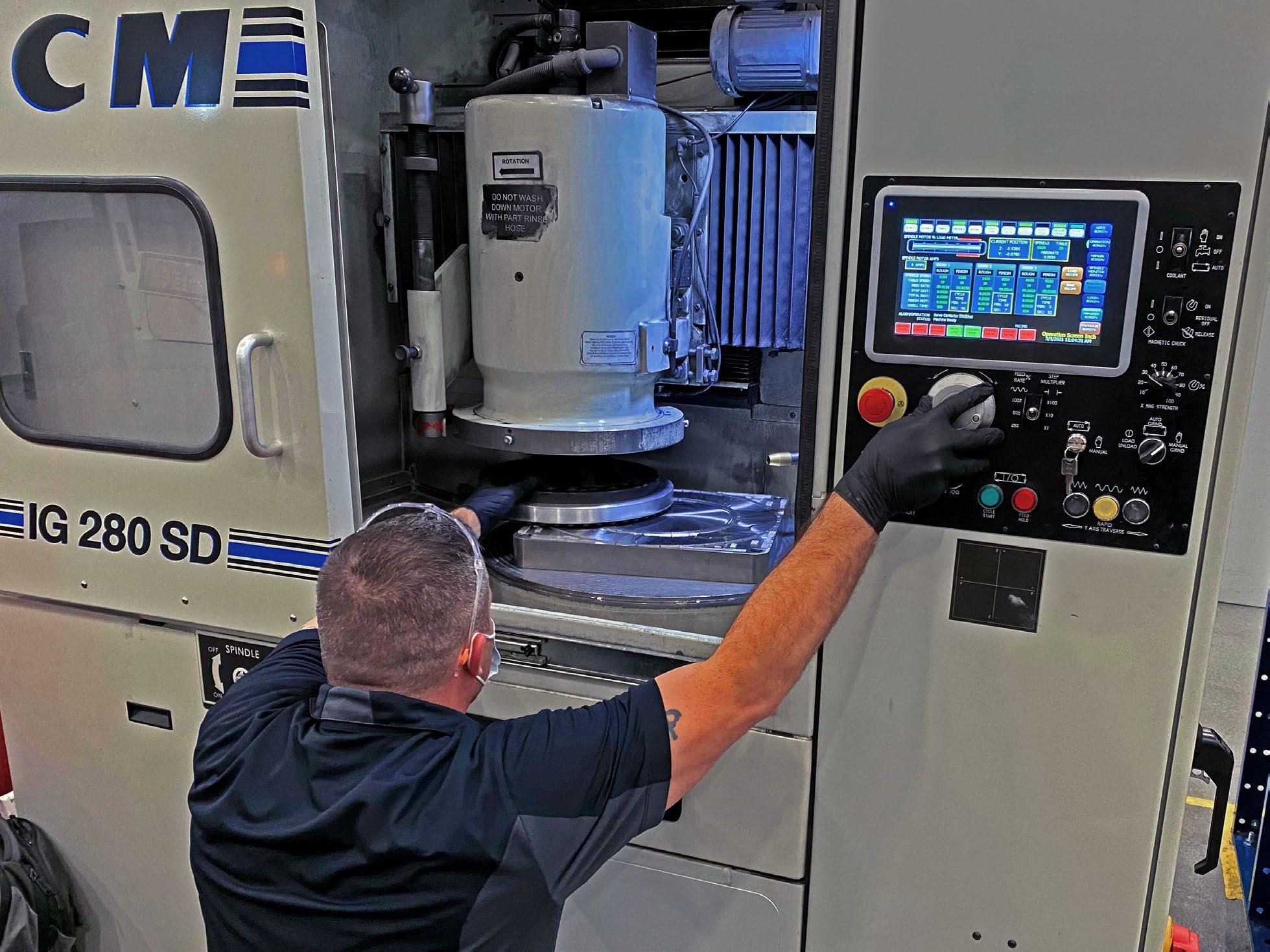
DCM SURFACE GRINDERS RESURFACE ADDITIVE BUILD PLATES FAST WITH » 12-48” MAGNETIC ROTARY TABLES » 10-50HP GRINDING MOTORS » SIMPLE TOUCHSCREEN CONTROLS » ADVANCED TECHNOLOGY www.dcm-tech.com | 800.533.5339 | 4455 Theurer Blvd. Winona, MN 55987
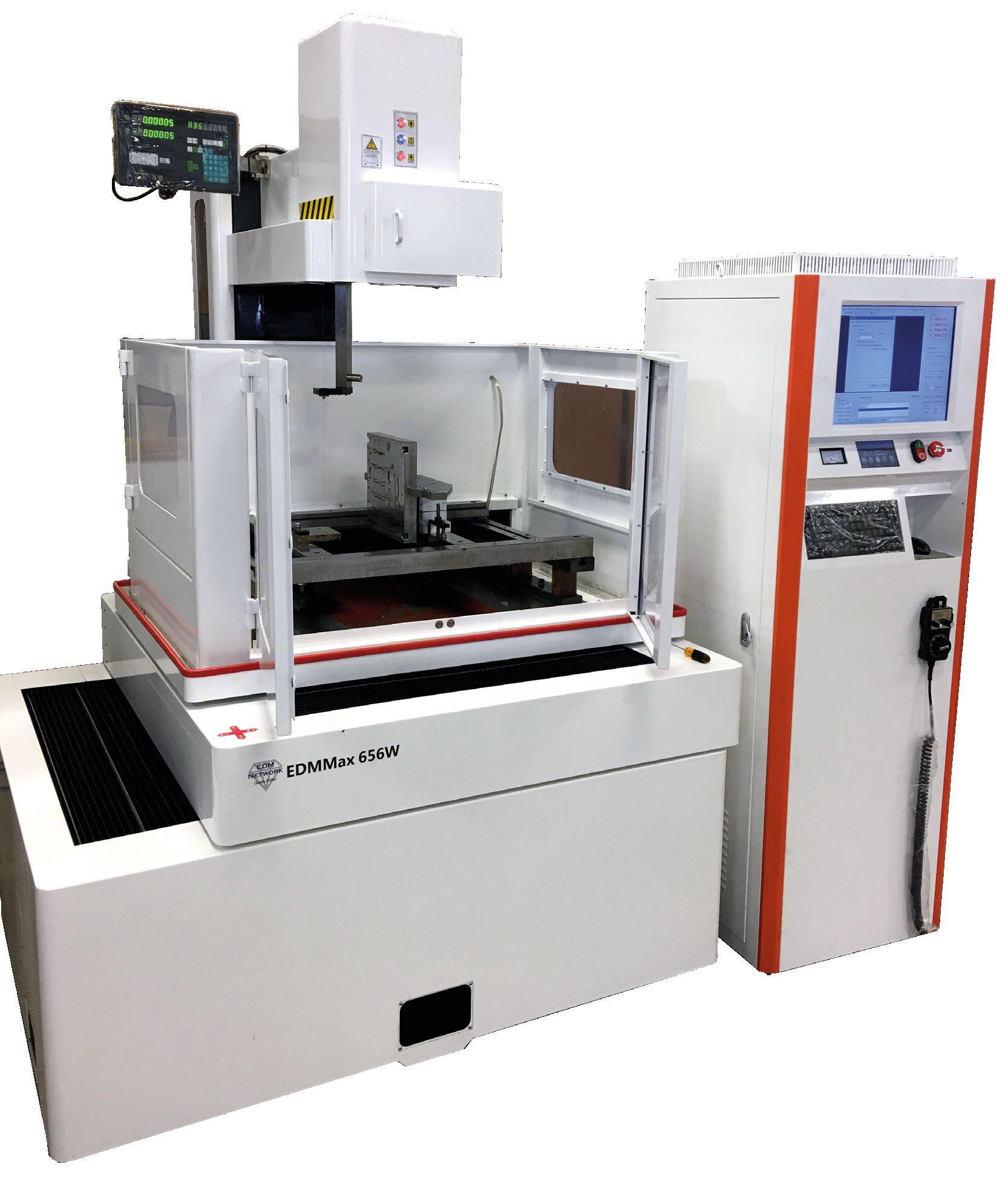

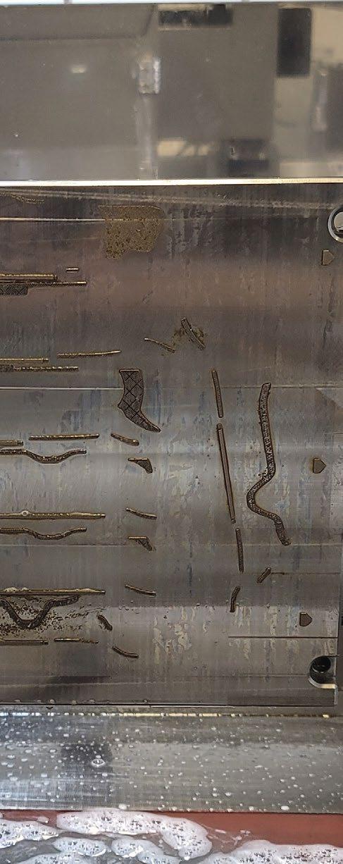
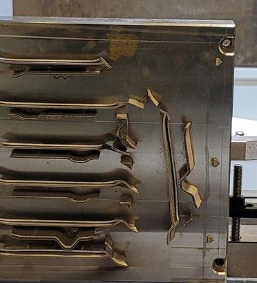
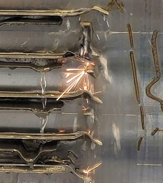
Industry News We have added a number of improvements over the standard Fast Wire Edms including: • Cutting capacity of 625 x 625 mm • Panasonic AC Servo motors and drivers • Hiwin Linear Guideways • Build in Cad System • Two filters • Increased height side walls to reduce splashing • View windows to see the wire progress • Automatic spent wire spooler • Optional build plate support fixture • Optional Anti Electrolisis (AE) Six sizes available: • 400x320x280mm V • 400x320x410mm V • 630x500x625mm V • 1000x800x1050mm V • 410x410x500mm H • 1100x1400x1250mm H V - Vertical | H - Horizontal 1974 Bucktail Lane, Sugar Grove, IL 60554 1-888-289-3367 www.edmnetwork.com EDM Network provides “Everything in EDM” The new model EDMMax 656W 37 min TIME TO CUT
Sauber Technologies and AM Solutions extend partnership

AM Solutions – 3D post processing technology, headquartered in Untermerzbach, Germany, a brand of the Rösler Group, has announced that it has extended its partnership with Sauber Technologies for an additional two years.
Automated post-processing of additively manufactured parts is said to be essential to Sauber Technologies for the economical production of repeatable and high-quality parts, especially on an industrial scale. Over the last year, the company benefited from Rösler’s experience in surface finishing, by using post processing equipment provided by AM Solutions. Several additively manufactured parts have also been featured on the Alfa Romeo F1 Team ORLEN C42.
Under AM Solutions, the Rösler Group assembles all activities related to Additive Manufacturing with a range of products and services, including systems, consumables and process engineering for the seriesready and automated post-processing of additively manufactured parts. Rösler’s experience in surface finishing in a real production environment as well as its own mechanical engineering is said to form a strong backbone of AM Solutions’ offerings.
As part of the relationship between Sauber Technologies and AM Solutions, the two partners are currently collaborating in the field of stereolithography in post-processing, to develop solutions to maximise the efficiency of the cleaning process and support removal. In addition, Sauber Technologies is already using several mass finishing and shot blasting machines from AM Solutions.
Christoph Hansen, COO Sauber Technologies, stated, “Over the past year, the partnership with AM Solutions has been of fundamental importance, as several business practices of our Group have been employing them, from the wind tunnel models to the most experimental components, and, of course, our Formula One cars. AM Solutions has brought its excellent experience and solutions to Sauber Technologies, helping us create 3D printed parts faster and in a more efficient way, two essential qualities for an ever-evolving business like ours. I am glad to be extending our partnership with the Rösler Group, and I am already looking forward to seeing what else we could achieve together in the future.”
Volker Löhnert, Managing Director of Rösler Oberflächentechnik GmbH, commented, “The extension of our partnership with Sauber Technologies is an important milestone for AM Solutions – 3D post processing technology. The team has a long tradition of using additively manufactured components in its Formula One cars and has been therefore interested in exploring the vast opportunities that 3D printing offers in terms of design, material selection, and lightweight
construction. High-quality and repeatable post processing is of great importance for the optimisation of the entire process chain, and that is where we bring our decades of expertise in surface finishing, together with our customised solutions developed specifically for the peculiarities of AM-manufactured parts. For these reasons, we have the perfect partner at our side in Sauber Technologies.” www.solutions-for-am.com www.sauber-technologies.com
Metal Additive Manufacturing | Winter 2022 69 Vol. 8 No. 4 © 2022 Inovar Communications Ltd | contents | news | events | advertisers | print sub | e-newsletter | GETPDF Industry News
Christoph Hansen, COO Sauber Technologies, and Volker Löhnert, Managing Director Rösler Oberflächentechnik GmbH (Courtesy AM Solutions – 3D post processing technology)
Utilis AG, MIMplus and Headmade develop tool holder with 185% performance increase
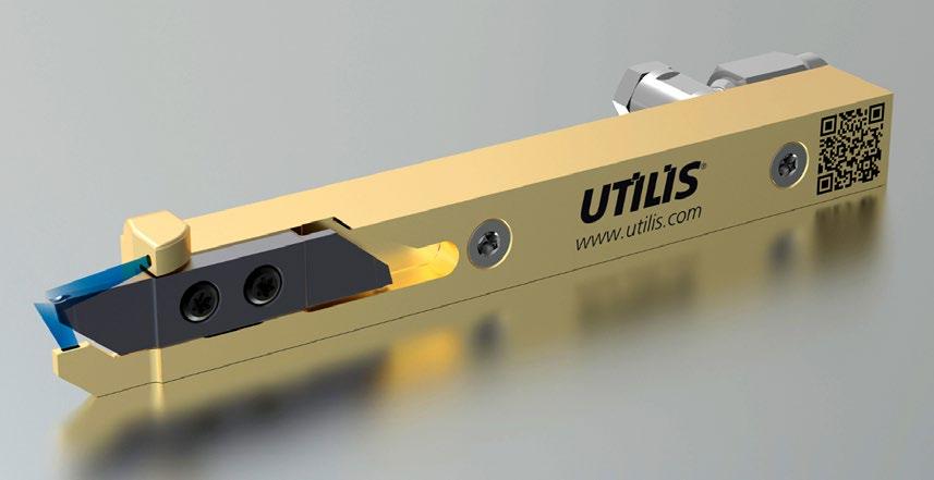
Utilis AG, Muellheim, Switzerland, has worked with German companies MIMplus Technologies GmbH & Co KG, Ispringen, and Headmade, Unterpleichfeld, to co-develop a cutting tool holder with a reported 185% performance increase.
This multidec® tool holder was specially developed for efficient grooving and longitudinal turning on sliding headstock automatic lathes
and can enable increased productivity in manufacturing. Via a new integrated cooling system, customers now have the opportunity to double the service life of their cutting edges or increase their cutting values without experiencing higher wear.
The tool holder is also said to benefit from Headmade’s newly developed M2 tool steel, which exhibits ultra-high wear resistance
and hardness. The very narrow additively manufactured cooling channels will result in a tool holder with ultra-high performance and a lifetime increase of up to 185%. These channels were reportedly made possible by utilising the ColdMetalFusion process, as the extremely small diameter of the cooling channels needed to be depowdered without damaging the green part. ColdMetalFusion is a sinter-based Additive Manufacturing process that reuslts in parts with properties similar to Metal Injection Moulding.
The tool holder includes extremely small cooling channels and is made using the ColdMetalFusion process - a sinter-based AM method that results in parts with properties similar to MIM (Courtesy Headmade Materials)
HZG Group invests in trinckle’s Series A funding round
Software specialist for design automation in Additive Manufacturing, trinckle, based in Berlin, Germany, has raised €3 million in its Series A financing round which saw lead investment from the HZG Group. This venture capitalist group, which was founded by Kerstin and Frank Carsten Herzog (the original founders of Concept Laser GmbH), supports Additive Manufacturing startups and related industry fields.
With this investment, trinckle aims to further expand its technological focus, strengthen its team and launch its software solution on a broad scale. According to the company, its software targets a central problem
of Additive Manufacturing: every application – regardless of the industry – is associated with a high manual design effort. So far, this construction or design work can only be done by a few experts in complex CAD programs. The paramate software solution developed by trinckle enables the simple automation of design processes that are suited to beginners or more experienced designers.
Florian Reichle, co-founder and managing director of trinckle, stated, “We are very pleased about the proof of trust in the face of the recession. Especially now, many companies are dependent on saving costs. In addi -
The partners set up two identical machines at both MIMplus and Headmade’s locations to jointly develop and quickly compare results across locations. This allowed for the effective and straightforward parameter development and verification of the M2 tool steel for the tool holder across locations. The three companies eventually reached a part density of 98% and resulted in a superior mechanical performance. Headmade Materials has launched the M2 tool steel with Utilis as its lead application. It is now available to the general public. www.utilis.com www.headmade-materials.de www.mimplus.de
tion to significant savings potential, our range of solutions offers the opportunity to simplify production processes and roll them out globally. This enables completely new digital processes and business models in the sense of Industry 4.0, which are prepared for the future.”
Marlene Vogel, co-founder and technical managing director of trinckle, added, “The recent financing round is the next milestone in the development of our company. We are thrilled to have HZG Group on board, the VC investor who is both entrepreneurially experienced and technically highly versed in 3D printing. This is exactly the right combination at the right time to now take the company to the next level and scale it up.”
www.trinckle.com www.hzg-group.com
Metal Additive Manufacturing | Winter 2022 70 © 2022 Inovar Communications Ltd Vol. 8 No. 4 | contents | news | events | advertisers | print sub | e-newsletter | Industry News


Materials R&D Customized Metal 3D Printer Fe Based Ti Based Ni Based SLM EBM DEB MIM BJ Co Based Powder Type Application HIP PVD MTI: (MTI is a Yuean group company) Materials Technology Innovations Co., Ltd. info@mt-innov.com Tel: +86 (0)20 3104 0619 www.mt-innov.com FOR MORE INFORMATION, CONTACT MTI Specialized in AM metal materials
Solukon marks delivery of 200th automated metal depowdering machine
Solukon, Augsburg, Germany, has announced that it has delivered its 200 th depowdering machine for metal Additive Manufacturing following the delivery of a SFMAT800-S to satellite component manufacturer SWISSto12.
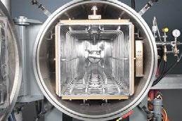
Since its foundation, Solukon has worked to highlight the advantages
of automated depowdering in the Additive Manufacturing process.
The introduction of its Smart Powder Recuperation technology in 2015 was reported to be the world’s first industrial system for automated depowdering. With well-known customers and partnerships, the company believes
that it has significantly optimised post-processing for the industry in terms of occupational safety and efficiency.
SWISSto12 uses its SFMAT800-S to clean complex parts automatically. Using Additive Manufacturing, the company supplies RFID antenna components and complex waveguide structures which are needed for satellite telecommunications, amongst other parts.
Sintervac AM debind and sinter vacuum furnaces for Additive Manufactured parts
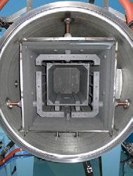
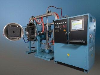
• Metal or graphite hot zones
• Processes all binders for metals or ceramics
• Sizes from 8-1500 liters (0.3–54 cu ft.)
• Pressures from 10-6 mbar to Atmosphere
• Precision heat treating post processing available
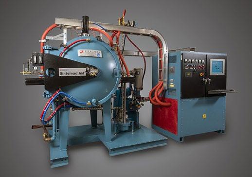
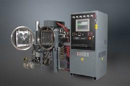
• Vacuum, Ar, N2 and H2
• Max possible temperature 3,500°C (6,332°F)
• Worldwide field service, rebuilds and parts for all makes
“By using Additive Manufacturing methods, we achieve a significant reduction in weight and costs – as well as excellent frequency performance – for our antennas,” stated Mathieu Billod, Head of Manufacturing Technology at SWISSto12. “With the Solukon SFM-AT800-S, we depowder the printed parts reliably and quickly. Due to the unlimited freedom of motion, even complex structures inside the parts become powderfree.”
The aerospace sector is the largest user of Solukon’s automated depowdering systems. “Aerospace is the industry with the most Solukon systems in the field, because the requirements for repeatable and reliable postprocessing are particularly high here,” added Andreas Hartmann, CEO and CTO of Solukon.
In total, the company has installed its depowdering machines – of which it now has four different models – in twentyeight countries. As well as the 200 metal powder machines, Solukon has also delivered polymer depowdering machines and has developed QC solutions, including integration into automated processes, as well as intelligent software in cooperation with Siemens (the SPR-Pathfinder).
“We are honoured that so many well-known companies, institutes and OEMs trust in our technology,” continued Hartmann. “For us, this means another kick to always grow with the challenges of our customers.”
www.solukon.de
Metal Additive Manufacturing | Winter 2022 72 © 2022 Inovar Communications Ltd Vol. 8 No. 4 | contents | news | events | advertisers | print sub | e-newsletter | Industry News
Centorr Vacuum Industries 55 Northeastern Blvd Nashua, NH 03062 USA
595 7233 Fax: +1
595 9220 Email: sales@centorr.com www.centorr.com/am Sintervac® AM WorkhorseTM AM
Tel: +1 603
603
Over 6,500 production and laboratory furnaces manufactured since 1954 ®
Researchers from the Chinese Academy of Sciences and its associated university have published a paper in Energy Storage Materials on the AM of lithium metal batteries with ultrahigh areal energy density, produced via the manipulation of their porosity.

Revolutions in Li-ion battery technology, spurred on by their growth, but the application of these advances can be prevented by factors like Li dendrite growth, low Coulombic efficiency and mismatched cathodes. In ‘All 3D printing lithium metal batteries with hierarchically and conductively porous skeleton for ultrahigh areal energy density’ the researchers additively manufactured conductive Ti 3C 2Tx MXene scaffolds with porous LiFePO 4 lattices to construct batteries with prolonged lifespans and higher energy density.
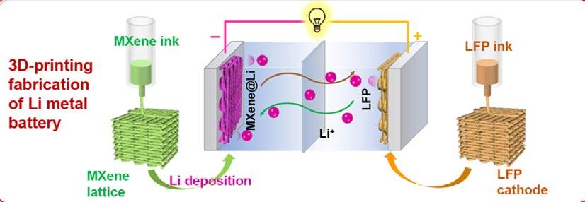
Graphical abstract demonstrating the means used to achieve a higher energy density and longer life in Li metal batteries (Courtesy Ma, J, et al, “All 3D printing lithium metal batteries with hierarchically and conductively porous skeleton for ultrahigh areal energy density”, Energy Storage Materials)
The exceptional ability of Ti 3C 2Tx to form a stable structure with lithium regulates the uniform deposition of metallic Li, allowing the stable MXene scaffold to achieve an areal capacity of 30 mAh/cm 2 at 30 mA/ cm 2 and a cycle lifespan of 4800 h. The full battery is assembled by rationally matching this dendritefree MXene-based Li anode with a hierarchically conductive LiFePO 4 framework at an ultrahigh mass loading of 171 mg/cm 2
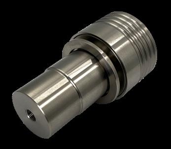
The as-assembled Li metal batteries are said to deliver unprecedented areal capacity of 25.3 mAh/ cm 2, a reportedly record-high areal energy density of 81.6 mWh/cm 2 and improved cycling stability of 500 cycles, breaking through the limitation of thick-film cathodes. The researchers believe that this outlines a viable option for the stable Additive Manufacturing of Li metal batteries. english.cas.cn
Metal Additive Manufacturing | Winter 2022 73 Vol. 8 No. 4 © 2022 Inovar Communications Ltd | contents | news | events | advertisers | print sub | e-newsletter | GETPDF Industry News Moisture and Oxygen Analyzers for Additive Manufacturing Market leaders for O2 safety-critical applications ProcessSensing.com • Fail-safe, SIL2-rated O2 analyzers • Highly stable, non-depleting sensors • Accurate low ppm measurements
More energy dense, longer-lasting batteries with AM
Shell produces and deploys first additively manufactured leak repair clamp
Global energy and petrochemical company Shell reports it has successfully installed its first additively manufactured leak repair clamp in service. Clamps, also known as mechanical leak repair enclosures, are engineered solutions that are used to encapsulate and restore integrity of operating pipelines against pipeline defects or wall thinning arising through erosion and corrosion mechanisms.
Traditionally, a simple clamp can be manufactured within 3-5 days, but complex clamps may take four weeks or more when factoring in delivery times. The ability to apply temporary repairs, however, is critical to enable facilities to remain on-stream. Defects can occur in diverse locations given the complexity of piping systems, often triggering the need for dedicated, customised solutions. The speed of response to restore the mechanical integrity and continuous safe operation of the asset is critical.
A proof of concept was executed collaboratively by Shell; TEAM, Inc.; and Vallourec. Together, the team established a technical specification and inspection test plan for what is being referred to as the first clamp with an industrial application to be produced completely via Wire Arc
Additive Manufacturing (WAAM), a wire-based Directed Energy Deposition (DED) process. The goal was to verify the feasibility of using a WAAM technique to produce clamps for leak repair which will meet the required quality assurance for mediumpressure steam systems. The proof of concept helped gather insights into the steps needed to improve the quality and productivity for future applications.
The resultant AM clamp successfully passed the burst test conducted at 142.4 bar (over 5 X the intended design pressure), satisfying the required technical readiness within Shell to qualify the part for field application.
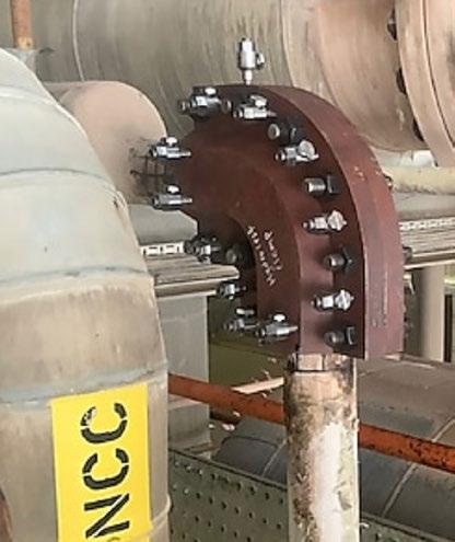
In this case, the overall delivery lead time was longer than for a conventionally manufactured clamp, as it was the first to be produced. This is because it falls under the highest criticality category under the DNV-ST-B203 Additive Manufacturing of metallic parts. Three sets of clamps were produced for extensive testing, though only one was eventually installed. As it was the first demonstration project, the team focused more on designing the clamp for a 100% inspection success rate rather than on design optimisation.
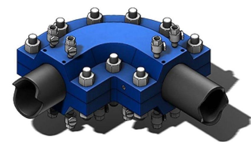
The project involved the shipment of the parts for Additive Manufacturing and testing at different locations and countries, which contributed to the lengthened lead time and costs. The different steps involved in the procurement process, as well as quality assurance & control were said to account for over 50% of the time required for the proof of concept.
The next phase will focus on ensuring the product quality and consistency, as well as reducing the lead time and costs of the AM of selected clamps by streamlining the qualification process and reducing the need for duplicable parts. It is intended that the future projects will enable the formation of a database with all inspection and qualification test results reflecting the quality variance in WAAM parts, as analysing this data can help reduce the criticality classification of AM spare parts, or the amount of nondestructive testing required prior to using the parts in production.
It will also enable the development of application specific qualification requirements, allowing more complex parts to be qualified based on case history and successful in-service use cases of simpler parts. There will also be the creation of a library of qualified configurations to reduce qualification efforts for the same or similar products in future.
www.shell.com
Metal Additive Manufacturing | Winter 2022 74 © 2022 Inovar Communications Ltd Vol. 8 No. 4 | contents | news | events | advertisers | print sub | e-newsletter | Industry News
Drawing of the additively manufactured clamp (left) and the final Additively Manufactured clamp installed at a Shell site (Courtesy Shell)
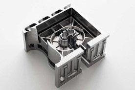
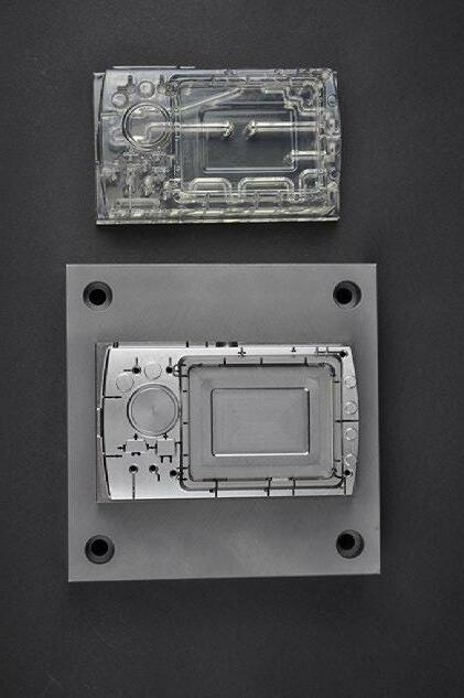
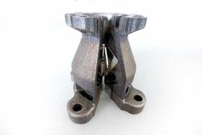
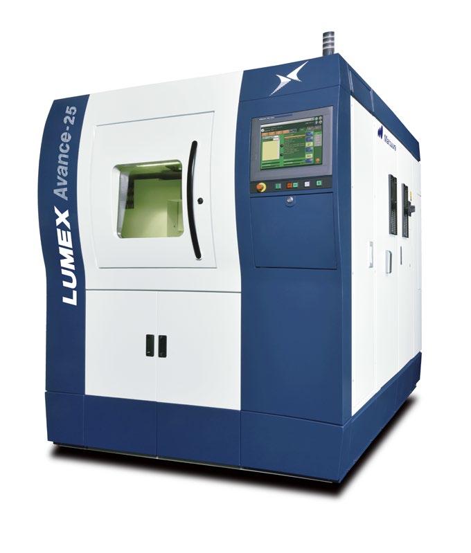


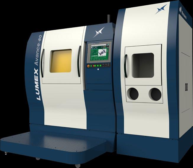
• Low carbon steel powder designed for Additive Manufacturing
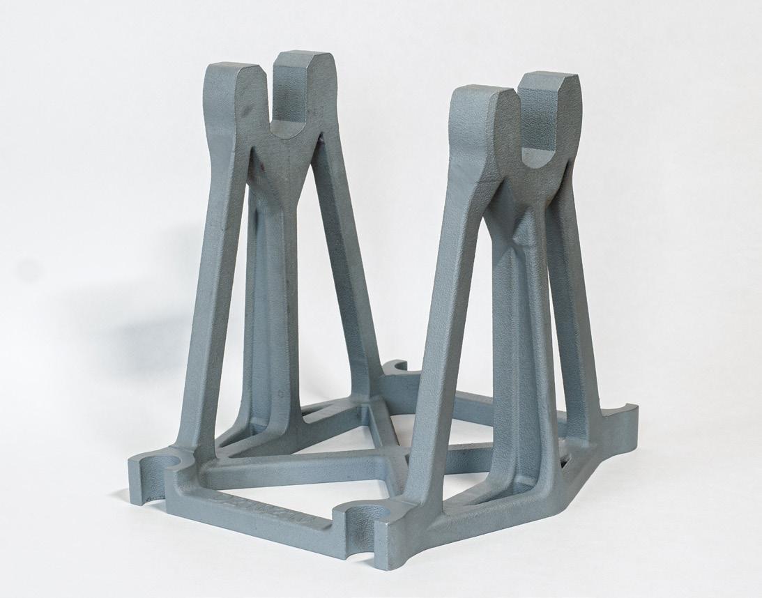
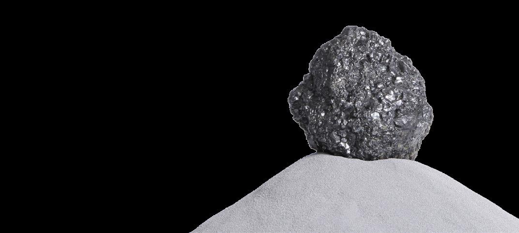
• Good flowability through powder nozzle and good spreadability in powder bed
• Suitable for different Additive Manufacturing Technologies
• To additively manufacture parts with mechanical properties superior to conventional methods
• Additional Additive Manufacturing steel powder grades in development
Emery Oleochemicals launches LOXIOL metal filament
Emery Oleochemicals, Düsseldorf, Germany, has launched its LOXIOL range of metal filaments for Fused Filament Fabrication (FFF), a Material Extrusion (MEX) Additive Manufacturing process. The LOXIOL portfolio is comprised of five materials, with each available in diameters of 1.75 mm and 2.85 mm. The materials include:
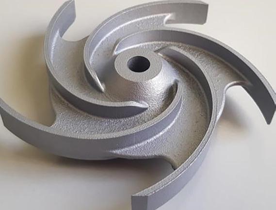
LOXIOL 316L: Offering high corrosion resistance, toughness, and ductility, as well as high acid resistance. This combination is said to be well suited to a wide range of applications in aerospace, automotive, energy, jewellery, medical, marine, and other industries.
LOXIOL 17-4 PH: Components made of LOXIOL 17-4 PH material have high corrosion resistance and high strength, a combination well suited to medical applications such as surgical instruments.
LOXIOL 718: This nickel-chromium alloy is suitable for use with high temperatures and corrosive conditions. Components additively manufactured using LOXIOL 718 have good tensile, fatigue, creep and fracture strength at temperatures up to 700°C, making them suitable for many high temperature applications such as gas turbine parts, medical instruments or parts for the power and process industries.
LOXIOL Copper: This high-purity copper offers good electrical and thermal conductivity making it suitable for a wide range of applications.
LOXIOL Ti-6Al-4V: TI-6Al-4V is a well-known light alloy, which is characterised by excellent mechanical properties and corrosion resistance combined with low weight and biocompatibility.
www.emeryoleo.com
World PM2024 dates confirmed
The Japan Powder Metallurgy Association (JPMA) and Japan Society of Powder & Powder Metallurgy (JSPM) have announced that World PM2024 International Powder Metallurgy Congress & Exhibition will take place October 13-17, 2024, in Yokohama, Japan.
World PM2024 will include presentations on the latest metal powder technologies, from press and sinter Powder Metallurgy and Metal Injection Moulding to Hot Isostatic Pressing and metal Additive Manufacturing.
Running alongside the international event, an exhibition will introduce the latest products and technologies from the industry supply chain. In addition, various social events and special programmes are planned.
www.worldpm2024.com
Metal Additive Manufacturing | Winter 2022 76 © 2022 Inovar Communications Ltd Vol. 8 No. 4 | contents | news | events | advertisers | print sub | e-newsletter | Industry News
ATOMET™ 1025
qmp-powders.com IATF 16949
we are additive

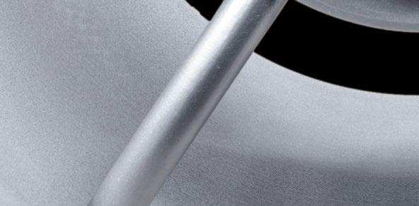
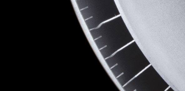
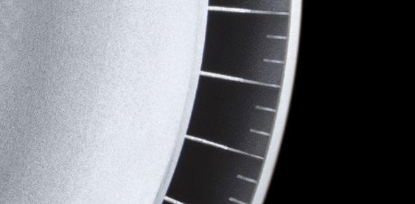

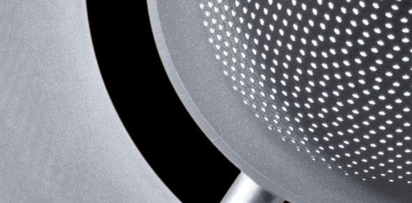
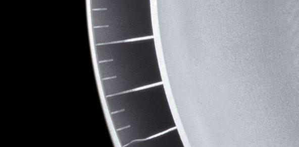
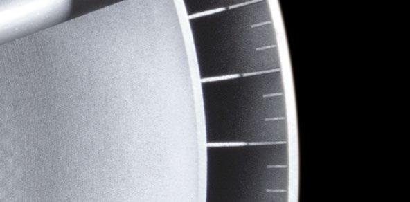
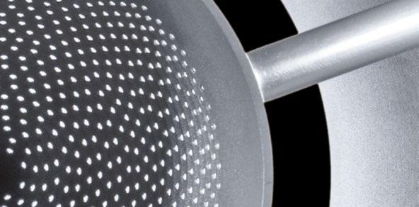
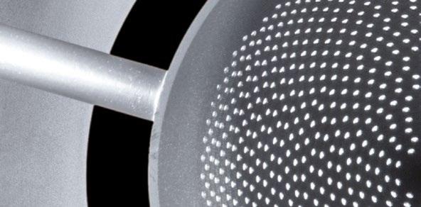


www.oerlikon.com/am Metal Additive Manufacturing and Product Development Partner
are Oerlikon AM
are integrating and scaling the entire Additive Manufacturing value chain to handle your project from A to Z. We partner with pioneers
you to revolutionize materials and manufacturing.
us.
time to rethink
in AM.
We
We
like
Come build with
It’s
what’s possible
EOS launches Contract Manufacturing Network for AM part production
EOS GmbH, headquartered in Krailling, Germany, has announced its new Contract Manufacturing Network that connects customers with established Additive Manufacturing production partners, enabling them to create additively manufactured parts quickly and reliably.
The network will initially focus on the Europe, Middle East and Africa
(EMEA) region, and includes the following seven partners: FKM, Erpro, Volum-E, Pankl, Materialise, Oerlikon, Hasenauer & Hesser. It is expected to expand globally, with more partners joining in the coming months.
With the new Contract Manufacturing Network, those searching for a trusted partner to produce AM parts, from rapid prototyping up to small
series volumes of 1,000 parts, can approach the network for support rather than manufacturing in-house.
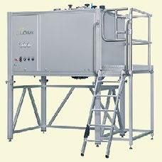
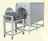
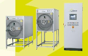

“We want our customers to be successful,” stated Markus Glasser, senior vice president EMEA at EOS. “When outsourcing their AM production to a partner from the Contract Manufacturing Network, small series customers will get the same EOS quality and industry expertise all our customers are used to. Our network partners are also able to act as pilot users for new technology developments at EOS, giving us valuable input and together developing the innovations that will shape the future of AM.”
To become a network partner, companies undergo a thorough and dedicated evaluation and must fulfil certain criteria, such as needing to serve customers across EMEA. Experienced partners must have a minimum of five EOS AM machines installed from the latest generation of machines, all being regularly maintained and inspected. EOS offers the tools required to ensure remote service as part of a preventive maintenance programme, enabling EOS production partners to provide high levels of performance and system availability.
Additionally, Contract Manufacturer Network partners must process either EOS or EOS ecosystem powder with their AM machines to ensure they can maintain the network’s quality promise. To ensure high quality standards, the partner must have a proven quality management system that complies with ISO 9001 and meets defined KPIs in areas such as customer satisfaction, scrap rates, and on-time delivery.
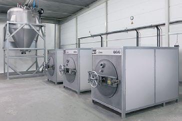
EOS Contract Manufacturing Network partners will be included in the MakerVerse partner hub, an EOSbranded platform on MakerVerse. With this, the network partners will have the opportunity to expand their reach to potential end customers while making the ordering process simpler.
www.eos.info
www.makerverse.ai
Metal Additive Manufacturing | Winter 2022 78 © 2022 Inovar Communications Ltd Vol. 8 No. 4 | contents | news | events | advertisers | print sub | e-newsletter | Industry News
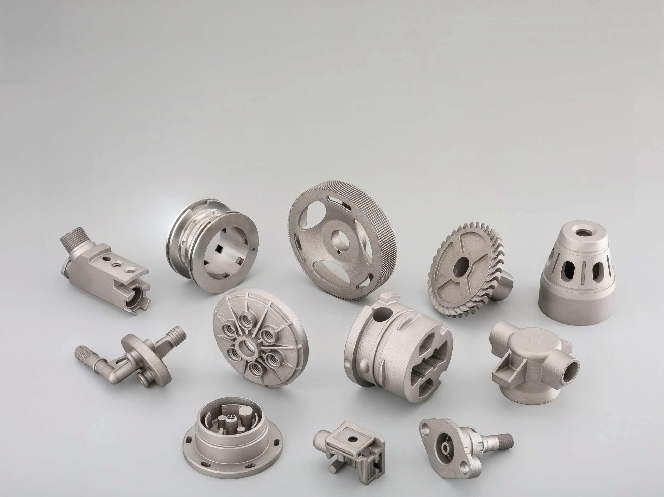
SLM Solutions presents new Software Partner Ecosystem
At Formnext 2022, SLM Solutions, Lübeck, Germany, presented its new software partner ecosystem. Comprised of some of the key software players in the Additive Manufacturing market, it is intended to assist its in-house software portfolio to deliver a comprehensive end-to-end AM software set. It is tailored to the customer’s individual requirements in build preparation, AM digitalisation, connectivity and quality assurance.
Nicolas Lemaire, Software Product Manager at SLM Solutions, stated, “This new software partner ecosystem – based on SLM Solutions open architecture – offers our customers the broadest and most compelling joint software portfolio to industrialise and take their AM operations to the next level, while overcoming key business challenges along the entire process chain.”
Build preparation
Materialise has been a key partner for SLM Solutions for many years. Its Magics software is a proven build preparation software for SLM Solutions’ products, both for industrial customers and as a basis for material development. “However, there is no one build preparation software that meets all requirements, each solution has its own merits,” explained Lemaire. “Thanks to our new partner ecosystem, customers can now choose the most appropriate build preparation software on the market that is best suited to the specifics of their application, and use it to design build job on their SLM machine.”
AM digitalisation
Digitalisation of the manufacturing processes and supply chains are on the rise in the AM industry and key asset for Industry 4.0, states SLM Solutions. In this context, manufacturers are seeking solutions to produce parts on-demand and
remotely to reduce inventory costs and lead times. One key requirement for this is the strong protection of the intellectual property of the part designs and a full traceability in the digital end-to-end manufacturing chain.
Lemaire explained, “SLM Solutions and its key partners, well established in the encryption market, offer its customers out-of-the-box solutions to achieve these goals, when implementing such distributed manufacturing models.”
Connectivity
One of the disciplines on the road to Industry 4.0 is the machine connectivity and the integration of the Additive Manufacturing operations into broader processes. This is required to scale up production, maximise process efficiency and reduce waste and operating costs. SLM Solutions used its open architecture to partner with Manufacturing Execution System (MES) and Internet of Things (IoT) solution providers in the AM space. SLM Solutions customers are expected to be able to implement such solutions into their SLM process to streamline and enhance production processes through automation, integration and full visibility on the additive manufacturing process.
SLM Solutions and Materialise are also collaborating on connectivity and secure digitalisation as part of SLM Solutions’ new software partner ecosystem.
“Materialise is proud to take the next step in the partnership with SLM. Welcoming SLM to the Materialise CO-AM ecosystem will empower innovators to take their AM operations to the next level, protecting build files, enforcing production rules, and enabling end-to-end data traceability,” added Vishal Singh, Senior Director of CO-AM. “Together, Materialise and SLM will deliver scalable and secure workflows for
serial production and distributed manufacturing to our current and future customer base.”
Another new partner in this field is software provider Oqton, with whom SLM will enter into a strategic partnership in an effort to increase productivity, shorten lead times, reduce costs and give complete traceability to industrial AM customers.
Roy Sterenthal, VP Industrial Additive, Oqton, stated, “The partnership between Oqton and SLM Solutions will allow our mutual customers to access and optimise AM workflows in one place, bringing an end to fragmented workflows. Customers will be well-equipped to meet the growing need for highly complex parts and serial production in industrial Additive Manufacturing. Oqton’s excellent solutions for SLM machines, including our Manufacturing OS for order management and planning, optimised AI/ML and simulationbased build preparation, will enable customers to streamline successful and certified workflows and ensure traceability.”
Quality
Quality assurance is a must for serial production. SLM Solutions offers its in-house QA software SLM.Quality, which is aimed at optimising process qualification and part validation activities. The software enables evaluation of the build job process data through standard dashboards and full documentation of the build process thanks to a friendly reporting tool.
SLM Solutions also partners with leading quality assurance software companies to enable customers to perform extended quality control through more powerful dashboards, combining different evaluation technologies like industrial X-ray Computed Tomography with 3D visualisation and automatic part & process defect detection through machine learning and artificial intelligence technologies.
www.slm-solutions.com
Metal Additive Manufacturing | Winter 2022 80 © 2022 Inovar Communications Ltd Vol. 8 No. 4 | contents | news | events | advertisers | print sub | e-newsletter | Industry News
Navigation

We’ve got one mission, to support as many metal part makers in the MIM and Metal AM industry as possible. Our team of processing experts utilize 20+ years of experience to share all our knowledge and help you overcome challenges, develop better processes and become successful part makers. We help develop real world, practical solutions based on many lessons learned along our journey. Being the ONLY debind and sinter service provider with full sized production equipment, we are honored that we have been able to support every industry currently utilizing MIM and Metal AM. DSH is the only source for the best process support, toll processing and educational resource for your MIM and Metal AM applications.


We offer: Remote Process Engineering, Small/Large Toll Processing, R+D projects, Educational Support on Total Process Management.


Your Partner in MIM/AM
and
In a complex industry, we’ll guide you the entire way. 107 Commerce Road | Cedar Grove, NJ 07009 USA | +1 973.239.7792 | dshtech.com
Support
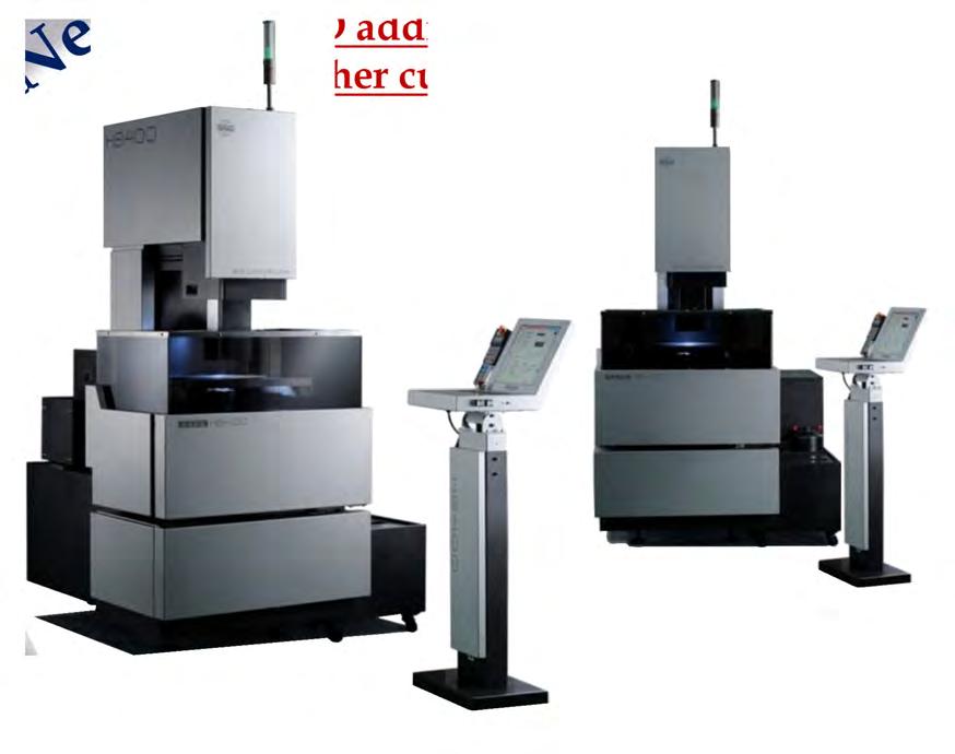
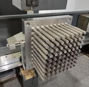


New Several models available Advantages: West Coast: 1-800-336-2946 Midwest / East Coast: 1-800-511-5532 Information@edmperformance.com * Z Height (up to 31.5”) * Large Table Sizes Available (1200mm travel) * Minimal Wire Breaks * Cost of Operation Under $1.00 per hour * 200-400% Faster than standard wire EDM * Simplified Setup * Ergonomic Interface WWW.EDMPERFORMANCE.COM MOLYCUT WIRE EDM 3D Metal Printed Part Removals Basic EDM Work and Cut O ffs See the video on youtube
Fraunhofer project utilises ultrasound to produce stronger AM parts
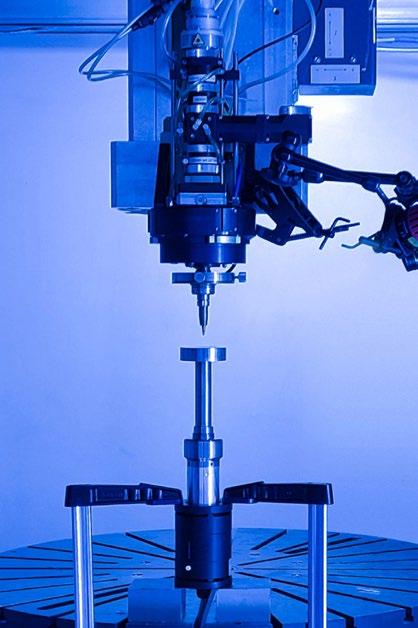
The Fraunhofer Institute for Material and Beam Technology IWS Dresden; the Fraunhofer Additive Production Technologies Facility IAPT, Hamburg, Germany; and the RMIT Centre for Additive Manufacturing, Melbourne, Australia, have begun a €4 million UltraGrain project with a meeting on ‘On-demand grading of grain structure by ultrasound-assisted AM – from demonstration to industrialisation.’
“Both Fraunhofer IAPT and Fraunhofer IWS have been cooperating with the Australian colleagues for a long time through personal contacts. UltraGrain, however, is the first project to receive funding that will lead directly to the transfer of joint research results into industrial practice,” stated Professor Ingomar Kelbassa, Executive Director of Fraunhofer IAPT and also Adjunct Professor at RMIT.
Considering the deepened cooperation, Fraunhofer-Gesellschaft is funding the project with €1.5 million from its International Cooperation and Networking ICON programme. The Australian partners are contributing a further €2.5 million.
The RMIT Centre for Additive Manufacturing project collaborators Associate Prof Andrey Molotnikov, Distinguished Prof Milan Brandt and Distinguished Prof Ma Qian are reportedly optimistic about the application of ultrasound to microstructure manipulation. They are reportedly convinced that the next generation of aerospace, as well as space part Additive Manufacturing, will significantly benefit from the uptake of the ultrasound technology which will be co-developed with the Fraunhofer partners.
In the process, the researchers are entering new technological territory. With the aim of specifically influencing the internal grain structure of AM components and, thus, their mechanical properties, researchers are combining the established wire- and powder-based Directed Energy Deposition (DED) processes
with ultrasound, which vibrates beyond the tones audible to humans. During the deposition process, the ultrasound sends fine vibrations with a precisely defined frequency globally through the resulting component or locally following the laser and directly to the melt pool, for example. The ultrasound prevents undesired columnar structures from forming in it – and these microscopic columns result in poorer mechanical performance. However, under ultrasonic action finer, round shaped micrograins are formed, being almost evenly distributed or graded and weakening the undesired texture.
This equiaxial alignment increases the mechanical and chemical loadbearing capacity of the additively produced work pieces among others. Because the ultrasound can be controlled in a targeted manner, component designers are able to specify exactly where the work piece will be subjected to great stresses later in use. There, the developers can plan for an ultrasound-controlled grain structure, but also decide at which points they can do without it in favour of faster production. Such grading is essential if, for instance, gas tanks for space probes have to endure the special challenges of outer space for years to come, or if tools in car factories have to resist even high point loads in mass production.
“With UltraGrain, we can significantly improve the properties like fatigue resistance, strength, toughness and ductility or reduce the cracking susceptibility of additively manufactured components,” stated Dr Elena López, project leader from the Fraunhofer IWS. “In addition, this project opens up the opportunity to establish new contacts in Australian industry and increase the international revenues of our institute.”
Fraunhofer IWS is contributing its experiences in laser cladding to the research alliance. In particular, emphasis will be placed on AM
processes involving equipment that feeds the desired titanium or steel alloys to the laser in wire form. Investigations with powder-based starting materials are also planned.
Fraunhofer IAPT deals with the optimal design of components with different grain structures. In the sense of a multi-material design, the scientists intend to develop a methodology for the optimal placement of ultrasonically influenced material areas. Furthermore, Fraunhofer IAPT is concerned with optimal path planning for the new process technology.
As international university partner in UltraGrain, RMIT Centre for Additive Manufacturing will explore the physical processes that ultrasound triggers in the material during the new process approach using advanced synchrotron measurements. The Australian team will also investigate possible scaling effects. During the transition from pure laboratory production of centimetresized components to additively manufactured series components that span several decimetres or even metres, unexpected side effects may quite possibly occur.
www.futuream.Fraunhofer.de www.additiv.Fraunhofer.de www.rmit.edu.au
Experimental set-up for ultrasoundassisted laser-directed energy deposition (Courtesy Fraunhofer IWS Dresden)
Metal Additive Manufacturing | Winter 2022 83 Vol. 8 No. 4 © 2022 Inovar Communications Ltd | contents | news | events | advertisers | print sub | e-newsletter | GETPDF Industry News
Precision ADM partners with Tecomet to shorten timelines, expand materials
Precision ADM, Inc., based in Winnipeg, Manitoba, Canada, has entered into a strategic partnership with surgical solutions provider Tecomet, headquartered in Woburn, Massachusetts, USA, in an effort to expand the development and production opportunities of Additive Manufacturing. This collaboration is anticipated to allow the companies to jointly leverage their resources and knowledge to yield expanded capabilities and capacity for each organisation, whilst shortening development times for customers.
The partnership is intended to allow for the expansion of Precision ADM’s Advanced Digital Manufacturing (ADM) processes, which have already produced millions of additively manufactured implants and instruments for the medical market. It will offer additional process experience into new material areas for Tecomet (including nickel alloys, aluminium, cobalt chrome, and 316 stainless steel), while expanding capacity in titanium and 17-4 stainless steel.
With the focus on driving lead time out of the manufacturing process, this partnership is expected to allow Tecomet to utilise its entire portfolio of capabilities, and combine the experience of Precision ADM, to meet the rapidly changing trends in the market.
with Tecomet, we will be able to offer clients shorter lead times and more efficient production with the same commitment to quality and manufacturing excellence for which we are both known. Our shared expertise and history in the medical device and aerospace industries leads to a naturally collaborative relationship. Precision ADM looks forward to a long and productive partnership with Tecomet.”
Precision ADM has produced millions of additively manufactured implants (Courtesy Precision ADM)
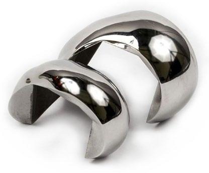
“We are thrilled to be partnering with Tecomet, an organisation with a history of excellence that clearly values Precision ADM’s highly technical and advanced manufacturing processes and capabilities,” stated Martin Petrak, president, and CEO of the company. “Together
GPM launches high-performance Al powders for wear-resistant AM
Gränges Powder Metallurgy (GPM), Velbert, Germany, a division of Sweden’s Gränges AB, has launched its second aluminium alloy aimed at the Additive Manufacturing sector. The high-performance aluminium alloy, S260 AM, is part of the company’s Dispal range and is said to be characterised by high wear resistance and excellent tribology properties.
The fine matrix structure of silicon particles coupled with Cu and Mg elements is intended to allow users to manufacture components that are natively highly wear resistant. Because the silicon is evenly distributed across the part, the material’s performance is said to be
long-lasting and permanent without the need for additional coating. Another key characteristic of this material compared to other Dispal materials is a low coefficient of thermal expansion, also due to the high silicon content. This makes S260 AM well suited to components that need to be machined on very tight tolerances and need to perform in challenging environments where they are subjected to temperature fluctuations (e.g., oil pump gears). Spool valves can be manufactured directly with matching CTE to their manifolds and without additional manufacturing steps. Valves made of S260 AM can reportedly perform millions of cycles, outperforming steel valves.
Bill Dow, president, and CEO of Tecomet, added, “We are excited about the partnership with Precision ADM. This initiative aligns with our steadfast approach to add value for global customers and provide full-spectrum, scalable manufacturing solutions. With this agreement, our customers will find a further commitment to innovation and continue to partner with Tecomet and our legacy of manufacturing successes. This commitment to growth excites me and I know our organisation will work diligently with the Precision ADM team to provide expanded additive-based solutions to our valued customers going forward!” www.tecomet.com www.precisionadm.com
“We saw a big need, especially in the automotive industry, for an alloy that is lightweight, wear resistant and at the same time has a low CTE,” stated Greta D’Angelo, Director of AM, GPM. “For many of our customers weight reduction is a big driver, and Additive Manufacturing allows them to go even further, without compromising on performance. Thanks to S260AM, our customers can break records and to do that more cost-effectively and with a shorter lead time.”
While S260 AM is another step for GPM into Additive Manufacturing, there are said to be plans for more material releases soon. Together with the development of new materials, GPM is working to address some of the main challenges that AM is still facing, such as serial production and high productivity.
www.granges.com
Metal Additive Manufacturing | Winter 2022 84 © 2022 Inovar Communications Ltd Vol. 8 No. 4 | contents | news | events | advertisers | print sub | e-newsletter | Industry News
Trends. Perspectives.

Forecasts. Undisputed, industry-leading report for 27 years Order your new 2022 report today! wohlersassociates.com
We know that additive manufacturing offers undreamed of potential. In addition to the printer, however you also need the upstream and downstream processes plus the experts, who have mastered the technology. You’ll only find all this at the AM highlight Formnext in November. For knowledge transfer, industry news and connecting with the AM community all year round visit formnext.com
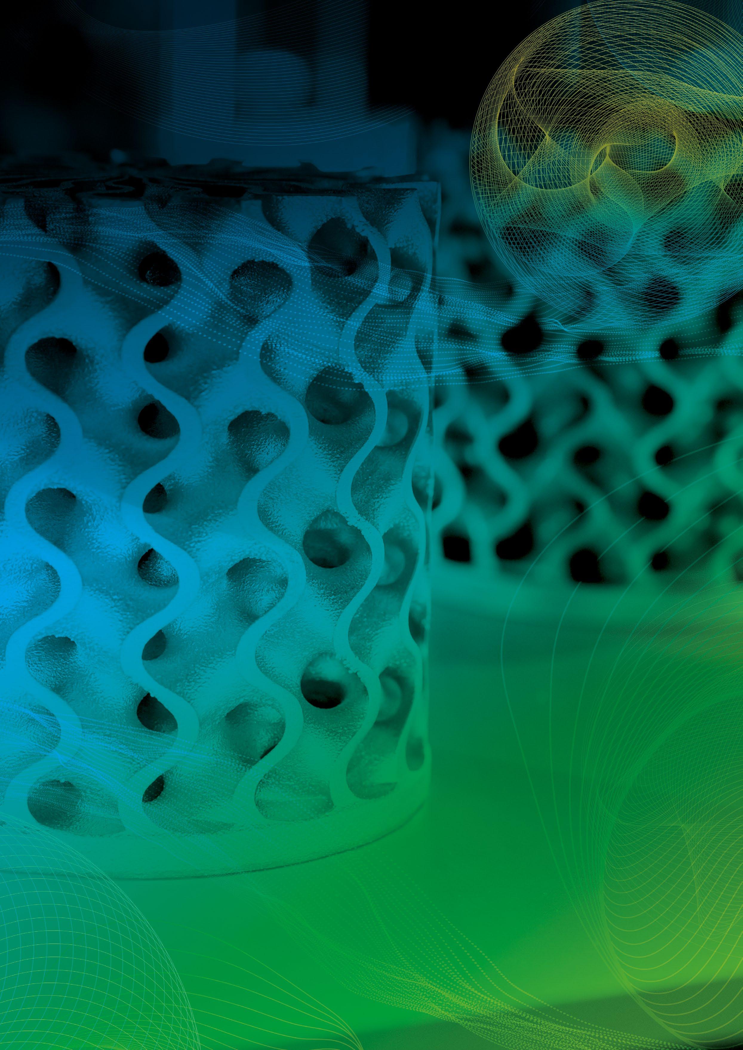
Be part of the fAMily! Make the impossible
Frankfurt Group #formnext
possible! Messe
WHERE IDEAS TAKE SHAPE.
What happens when you take the powder out of AM? Charting the rise of wire-based DED with WAAM3D
While most people associate the advantages of AM with small- to mediumsized, complex parts, wire-based Directed Energy Deposition (DED) makes it possible to achieve geometric complexity on a huge scale. Although the adoption rate for wire-based DED does not come close to that of the more widely known metal AM processes, this unique technology has advanced dramatically over recent years, and promises major advantages in a volatile global manufacturing landscape. Dr Filomeno Martina, CEO and co-founder of WAAM3D, explains more.
If I mention metal Additive Manufacturing to you, you’ll most likely think about optimised jet engine fuel nozzles, bionic brake callipers, or complex auxetic lattice structures. Lasers; powders; parts that you can hold in the palm of your hand. If you mention metal Additive Manufacturing to me, my mind will wander amongst critical fuselage frames, huge satellite bulkheads, advanced ship propellers. Electric arcs; wires; components that would fill a small bedroom.
For decades, the majority of the industry has focused on powder-based metal Additive Manufacturing. Particular attention has been on variants based on powder bed AM, which use either electron or laser beams (PBF-EB, PBF-LB) to provide the energy required to melt the powders in the desired pattern, layer by layer. Such technologies have opened previously unattainable doors in terms of design, with mechanical performances maximised whilst minimising mass. The
main enablers? Small particles, thin layers and surgically precise heat sources, together delivering net-shape parts. Powder-based developments have been a dream for the modern engineer, enabling them to truly design for function.
A changing manufacturing climate
However, the challenges facing manufacturing are changing, particularly due to the growing pressure to reshore operations and mitigate
Fig. 1 A 2319 aluminium wind tunnel model featuring a nose cone produced by WAAM3D for the UK's Aircraft Research Association, demonstrating that prototypes can be developed quickly and to defined tolerances using DED-Arc. Material usage was reduced by 74%. Activity funded by a Clean Sky 2 research and innovation programme under GA Agreement 864803 (Courtesy WAAM3D and ARA Ltd)
Metal Additive Manufacturing | Winter 2022 87 Vol. 8 No. 4 © 2022 Inovar Communications Ltd | contents | news | events | advertisers | print sub | e-newsletter | GETPDF
AM
WAAM3D: the rise of wire-based
risk, and the back-to-back disruptions of COVID-19 and the Russian invasion of Ukraine. These global crises have shown how unpredictable globalised supply chains can be. To protect profit margins against inflation, companies are increasingly being forced to rearchitect their supply chains, enabling them to change prices at a higher
frequency. The much-needed attention on environment and societal impact is also driving organisations to design both their products and their manufacturing processes for sustainability. Lastly, considering the ever-increasing pace of innovation, manufacturing methods are needed that can launch and improve products more and more quickly.
“To protect profit margins against inflation, companies are increasingly being forced to rearchitect their supply chains, enabling them to change prices at a higher frequency. The much-needed attention on environment and societal impact is also driving organisations to design both their products and their manufacturing processes for sustainability.”
Arguably, there is scope to seek those changes across the board, not just for relatively small parts, but, perhaps even more importantly, for larger components. There is, however, a necessary trade-off between accuracy and speed with Additive Manufacturing. For those large components that require less precision, processes such as DED-Arc (the ISO/ASTM 52900:2021 term [1] for what WAAM3D Ltd has trademarked as Wire + Arc Additive Manufacturing, or WAAM [2]) can deliver numerous advantages compared to more traditional methods.
What is DED-Arc?
The combination of an electric arc as the heat source and wire as feedstock has been investigated for Additive Manufacturing since the 1990s [3]. Despite the birth of AM being traditionally associated with the rise of stereolithography in the
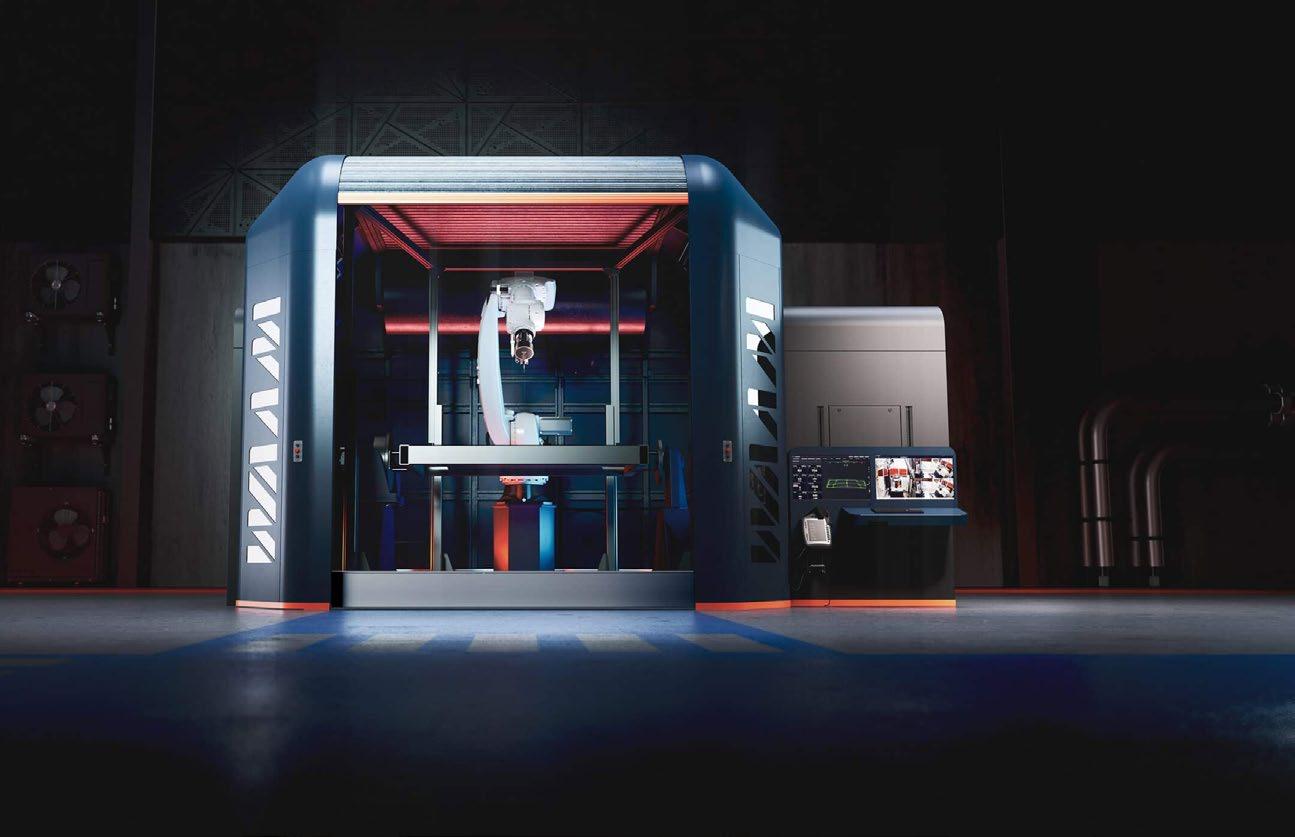
Metal Additive Manufacturing | Winter 2022 88 © 2022 Inovar Communications Ltd Vol. 8 No. 4 | contents | news | events | advertisers | print sub | e-newsletter | WAAM3D: the rise of wire-based AM
Fig. 2 WAAM3D’s RoboWAAM Advanced, a large format DED-Arc platform featuring proprietary sensing hardware and software, that has increased the potential for multi-metre metallic part development and manufacture in aerospace, defence, oil and gas and research communities
1980s, the first patent for Directed Energy Deposition was actually filed in 1925 [4] by R Baker, and was for making decorative articles. The patent stated, “This invention relates to ornamental arc welding, more especially to utilising an electric arc, such as is ordinarily employed for electric welding, for the formation of deposits to produce receptacles or containers of ornamental and useful shapes. I have found that metal derived from a fusible metal electrode by the passage of a current therethrough may be so deposited in superposed layers as to form various articles of an ornamental and useful nature, it being among the objects of my invention to produce such objects of various designs” [5]. With the benefit of time and development, AM has become so much more than Baker could ever have envisaged.
One of the key characteristics of the DED-Arc process (and the one that induces the user to consider it a straightforward technology to master) is its accessibility. In its most basic configuration, the DED-Arc process relies on standard, off-the-shelf welding equipment: welding power sources and torches, and wire-feeding devices. The choice of motion system is largely based on either anthropomorphic robotic arms, often combined with servo positioners, or computer numerical controlled (CNC) gantries. The majority of engineering companies will have access to most, if not all of these items.
It is unsurprising, then, that after the seminal work carried out at Cranfield University (first in the 1990s under the guidance of Prof John Norrish [6], and then with renewed vigour from 2006 onwards under Prof Stewart Williams), many engineers, material scientists, and students have been dipping their toes in the waters of DED-Arc. Academic publications in this field have grown from literally a handful in 2009, when there were no commercial solutions for DED-Arc, to many hundreds in 2021, as the competitive landscape finally begins to get busy and to diversify.
Fig. 3 A 1.2 m long Ti-6Al-4V wing spar demonstrator, built at Cranfield University for BAE Systems in 2012, in the as-built condition. It demonstrated successful control of distortion and the possibility to deposit large components back-to-back, however it also highlighted the requirement for better thermal compensation strategies to control the layer height in critical areas (Courtesy Cranfield University and BAE Systems)
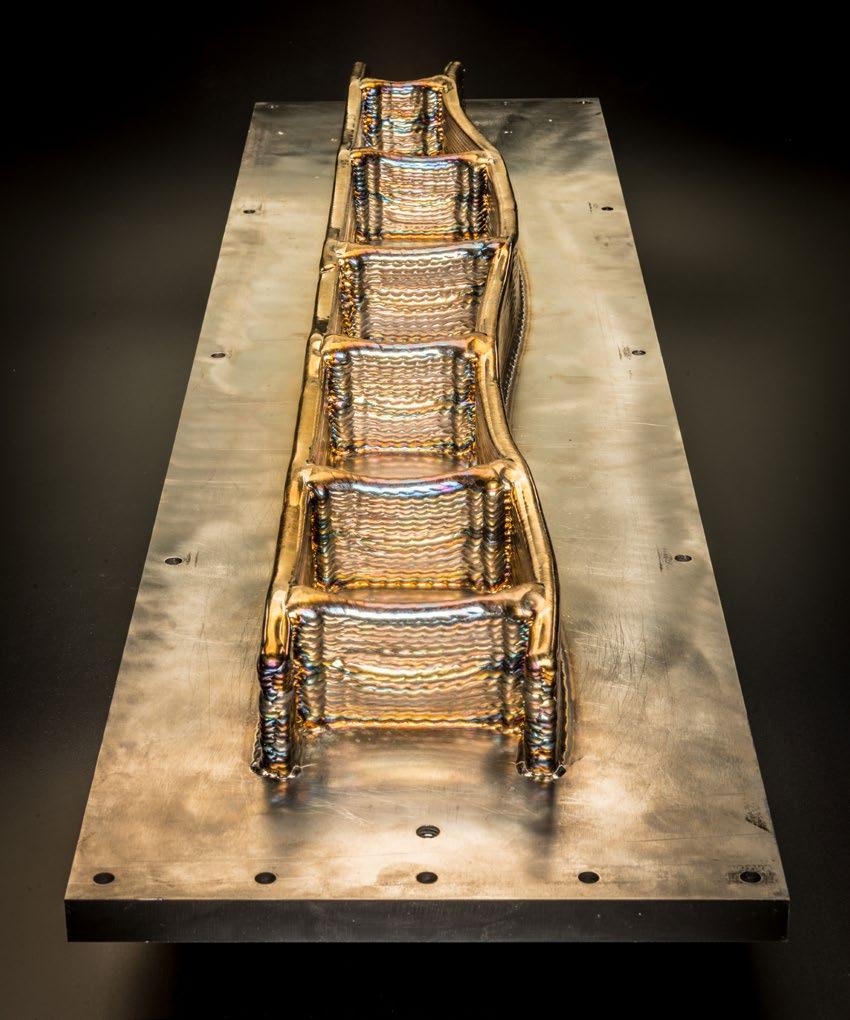
DED-Arc’s raison d’etre
DED-Arc involves a robotic arm tracing slow movements, inside a safe perimeter, possibly within an inert argon environment, with an ionised stream of gas melting wire feedstock in a highly controlled manner. Apart from being a hypnotising process to watch, why is the DED-Arc process becoming so fashionable? The answer can be summed up in one word: waste. This is in the continuous improvement, or kaizen , sense of the word, as DED-Arc helps manufacturers manage issues such as overproduction, inventory, motion, defects, over-processing, waiting, and transport.
Reduced metal swarf
Despite closed die forging making huge strides forward, traditional forging still leads to high material wastage. DED-Arc can significantly reduce the amount of material wasted on component creation. In the aerospace industry, the buy-to-fly (BTF) ratio is the ratio of the mass of the starting billet of material to the mass of the finished part that is flown on the aircraft. The smaller the ratio, the less material is wasted. The BTF ratio for aero engine components can be as high as twenty-five; sometimes, for aerostructures, as high as sixty. DED-Arc can reduce this ratio to less than two. It can’t reduce it to one, however, because the DED-Arc
Metal Additive Manufacturing | Winter 2022 89 Vol. 8 No. 4 © 2022 Inovar Communications Ltd | contents | news | events | advertisers | print sub | e-newsletter | GETPDF
the rise of wire-based AM
WAAM3D:
Fig. 4 A 24 kg Ti-6Al-4V landing gear rib, built
For the first time, it featured four deposition strategies (single,
compensation to minimise thermal field variability, innovation
build (second side not shown) with no distortion (Courtesy Cranfield
process, by virtue of its thicker layers (typically 1 to 3 mm thick), delivers near-net shape parts, with a couple of machining passes normally required to eliminate surface waviness. With this aside, the impact on cost reduction is still relevant; for example, in Ti-6Al-4V, if the traditional manufacturing route delivers a BTF ratio of four or above, DED-Arc is a cheaper alternative [7,8].
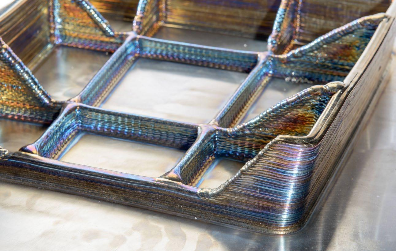
Reduced pre-machining wastage
The moulds and dies used for forging and casting can have long procurement times and high costs. Due to lead time and design cycle pressures, the purchase of tools must sometimes begin before the part’s design has been finalised. To overcome this, many manufacturers add a larger waste envelope into the final geometry of the mould or die, leading to increased levels of material waste to achieve the final product. As DED-Arc is a digital
manufacturing process, it requires no tools – apart from the clamps needed to fix the starting feedstock – so the upfront non-recurring cost is virtually eliminated, and design changes can be made whenever needed, eradicating additional geometry waste.
Reduced spare part wastage
For spare part, inventory management and stock keeping there are two types of potential waste: the material
itself, if the part isn’t needed, and the energy embodied into the part. Unused stock can lead to significant financial and material waste. Rather than keeping stock that might not be needed, more manufacturers are reducing inventory and logistics costs by focusing on local, on-demand manufacture. This helps them to resolve spare part production and repair issues, as quickly and as costeffectively as possible.
Metal Additive Manufacturing | Winter 2022 90 © 2022 Inovar Communications Ltd Vol. 8 No. 4 | contents | news | events | advertisers | print sub | e-newsletter |
WAAM3D: the rise of wire-based AM
at Cranfield University for Bombardier in 2013, in the as-built condition.
parallel, weaving and oscillated), advanced thermal
in design for DED-Arc, and asymmetric double-sided
University and Bombardier)
“Rather than keeping stock that might not be needed, more manufacturers are reducing inventory and logistics costs by focusing on local, on-demand manufacture. This helps them to resolve spare part production and repair issues, quickly and as cost effectively as possible.”
Improved environmental performance
Because of the material savings achieved using DED-Arc, a manufacturer’s environmental performance can be improved when it comes to component creation and repair. DED-Arc has long been used to repair structures, extending the life of components, and delivering significant energy and CO 2 emission savings. Additional environmental benefits can be unlocked by having local DED-Arc centres, thus reducing the impact of logistics. For those manufacturers looking to demonstrate that they are taking the triple bottom line seriously, the DED-Arc process is an important part of the large-scale metal component fabrication toolkit.
Beyond eliminating waste Moving beyond waste elimination, two more DED-Arc capabilities must not be forgotten:
1. The possibility of playing with material composition
2. The capability to reliably extend a component’s useful life by carrying out repair or remanufacturing operations
When it comes to material composition, Cranfield University has demonstrated the viability of in-situ alloying by providing as many as three wires of dissimilar composition to achieve a modified aluminium 2024 variant [9]. Indeed, the deposition of graded structures with materials as exotic and challenging as molybdenum, tantalum, and tungsten [10] has illustrated how multi-material components could become the new norm.
In terms of repair and remanufacturing, with the DED-Arc kit able to adapt to depositing on existing structures, service centres could be scattered around the world, to perform local repairs at the point of use. This is already beginning to happen and the potential for it is huge for reducing environmental impact even further by taking transportation out of the process.
Fig. 5 The Plasma Transferred Arc variant of WAAM3D’s End-Effector. It features double wire feeding for increased deposition rates, or multi-material deposition; a closed-loop-based wire positioning system for consistent transfer of metal drops; a leading pyrometer to ensure a consistent deposition-start temperature; a trailing pyrometer to monitor the temperature profile behind the melt pool; a melt pool monitoring camera with video feed sent to the control centre and recorded throughout the building of the part; and finally ShapeTechTM, WAAM3D’s proprietary sensor to measure layer height and 3D profile in real time; all connected to the WAAMCtrl® software. The variant shown also features a local shielding device for the deposition of reactive metals. WAAM3D has commercialised several End-Effector variants, provided either as part of RoboWAAM, or on their own
So, how has DED-Arc made the move to a viable, scalable industrial solution? This is largely thanks to research carried out at Cranfield University. Due to the institution’s long-standing aerospace heritage, and Prof Williams’ previous indus -
trial experience, it made sense that large-scale titanium structural components were the starting point for Cranfield’s DED-Arc research. The growing use of carbon-fibrereinforced-polymers on commercial aircrafts pushed the fraction of titanium components up, and with machining from forging or billet being the only two routes available, the requirement for a less wasteful
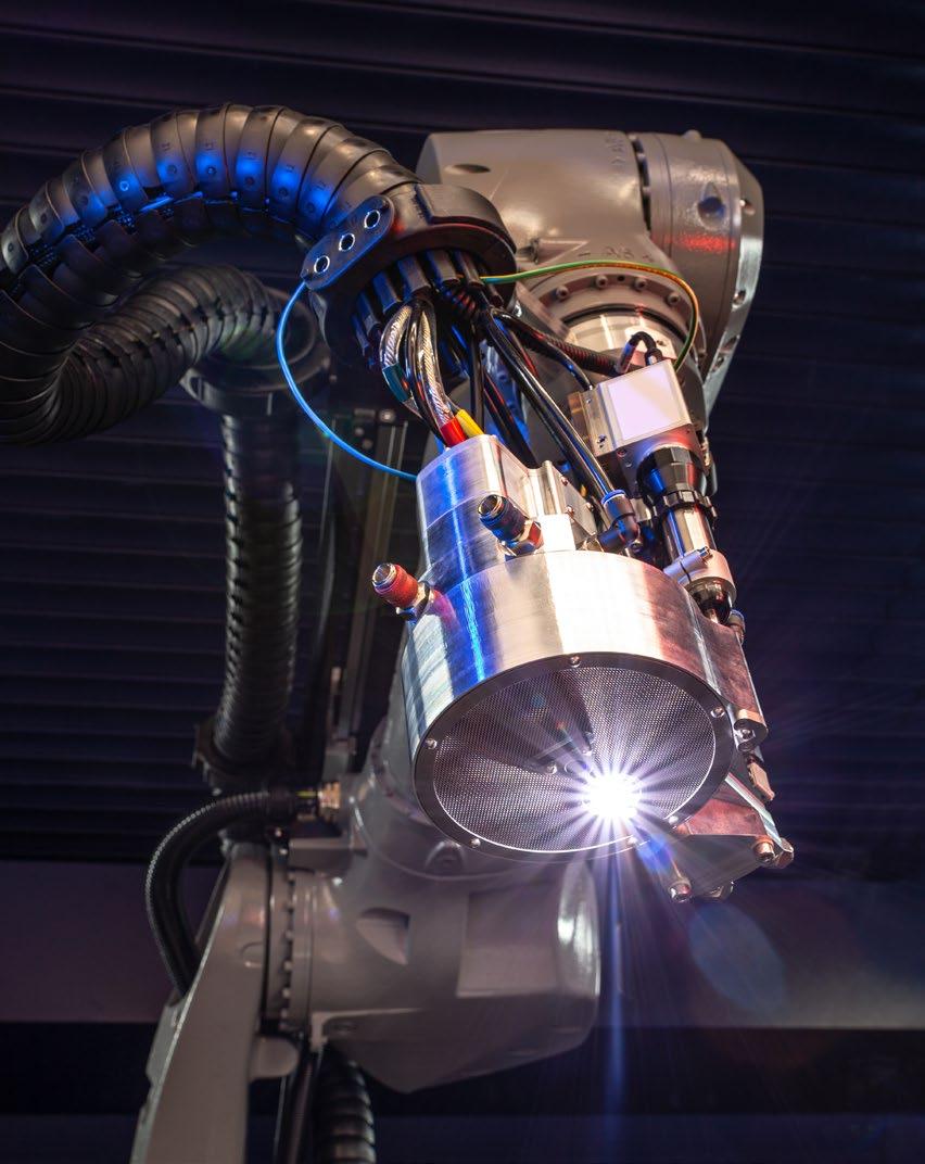
Metal Additive Manufacturing | Winter 2022 91 Vol. 8 No. 4 © 2022 Inovar Communications Ltd | contents | news | events | advertisers | print sub | e-newsletter | GETPDF
A r oute to industrial exploita tion
AM
WAAM3D: the rise of wire-based
Fig. 6
Distortion control for parts of this type was fixed by this time, however geometry control made this component incredibly difficult to make. For aluminium deposition there is little choice outside MIG-based processes, with which it is hard to control material feed and heat input independently. This is a key requirement when dealing with intersections, to achieve the target layer height whilst avoiding lack-of-fusion defects (Courtesy Cranfield University and Thales Alenia Space)
efficiency and rigour needed for such levels of consistency. Cranfield initially tried to work with existing providers of Computer Aided Manufacturing software, but eventually a DED-Arc-specific tool-path-planning solution was born (WAAMPlanner®). This was complemented by process algorithms, analytical solutions, and fluid-flow models that, based on geometry and alloy, would calculate location-specific primary process parameters (WAAMKeys). From an industrial perspective this development was crucial, as it enabled the prompt translation of preform design to executable machine programmes, minimising parameters’ development effort.
and costly manufacturing process became more and more urgent.
The first large-scale parts Cranfield University ever produced, back in 2012, were a 1.2 m-long, 20 kg wing spar for a fast jet, and a 24 kg landing gear rib, both in Ti-6Al-4V. Robots were programmed with Matlab routines and sets of parameters were limited in extent and capabilities. During the process, issues with controlling shape and integrity reliably became obvious. These issues were different from powder-bed technologies, however. That is because in DED, the deposited feedstock’s layer height is not fixed, and thermal effects related to local changes in thermal inertia are immediately visible, and often catastrophic.
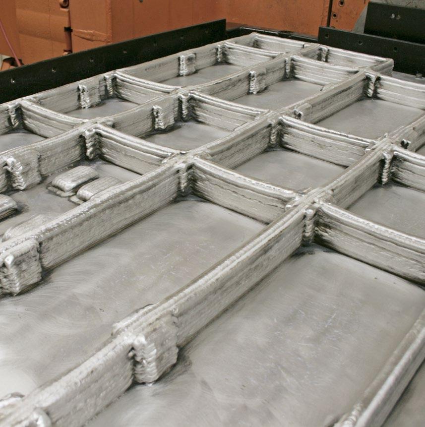
Considering the scale at which the melt pool is established, even small inaccuracies or perturbations to the stability of melting and solidification behaviour can cumulatively result in large drifts away from the target geometry. Moreover, as HIP is inapplicable as a method to eradicate defects on structures of this size, the geometrical challenge Cranfield faced was compounded by one of structural integrity, with the absolute requirement to avoid discontinuities during the DED-Arc deposition process.
The Cranfield team faced many challenges along the way. The first issue was developing software tools for trajectory generation, parameter allocation and process monitoring and control, that could achieve the
Another challenge has been to be able to demonstrate compliance in a repeatable manner for DED-Arc components. To achieve this monitoring and control accountability, a radically different approach to sensing had to be conceived and delivered – after all, without measurement there is no appreciation of a process’ recurring performance. However, the difficulty that had to be overcome was to avoid inundating the operator with an unmanageable quantity of data. As a result of this conundrum, WAAMCtrl® was developed to record and structure the data into a user-centric dashboard, featuring real-time colour-coding of the 3D picture of the build based on actual vs expected data, automatic following of the end-effector’s digital twin, and through-layers navigation to review and monitor the state of the part.
Modelling and simulation were other hurdles that had to be overcome. Initially, the floorplan of a prototype system with two robotic arms was sketched out that had each sliding onto 10 m tracks, on either side of a pair of rotators and tailstock. A 6 m aluminium beam was manufactured (Fig. 8), and the team was deceived into thinking that a big format machine equalled being able to build huge parts. Once the same system was upgraded to build with titanium
Metal Additive Manufacturing | Winter 2022 92 © 2022 Inovar Communications Ltd Vol. 8 No. 4 | contents | news | events | advertisers | print sub | e-newsletter |
WAAM3D: the rise of wire-based AM
Close-up of an as-built 2319 satellite breadboard, built at Cranfield University for Thales Alenia Space in 2016, in the as-built conditions.
Fig. 7 A screen grab of one of WAAMCtrl®’s interfaces. WAAMCtrl is the operating system and digital quality control tool of RoboWAAM, and for the first time it brings sensor fusion to large scale metal AM. It enables the monitoring, control, digital twin mapping, hardware and health and safety management of a component, as it is being produced. As well as enabling operators to have a fully controllable production process, WAAMCtrl® also produces fully auditable data storage, quality logs, and interactive data navigation to enable the demonstration of compliance in a fully repeatable way
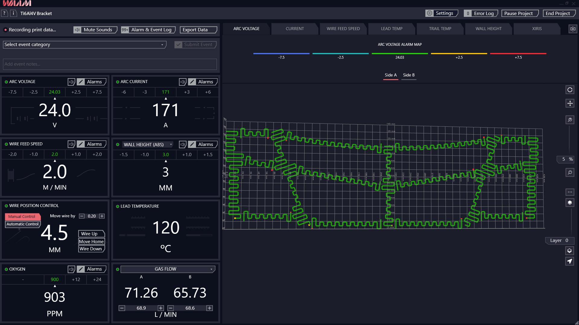
alloys, the deposition of a 2 x 1 m fuselage frame was attempted. However, it didn’t go to plan; the first trial had to be aborted two layers in due to catastrophic buckling distortion. Despite being deposited on an 18-mm-thick Ti-6Al-4V substrate, one of the corners came up by a foot once unclamped.
The team went back to the drawing board, and new tooling solutions were developed, based on conformal and compliant approaches, which were subsequently tested on scaled geometries. FEA models assisted in the optimisation of the build sequence, section by section, side by side, layer by layer. Also, the precise primary deposition parameters required to walk on the razor’s edge of feasible process, design compatibility, geometric integrity and validity were recalculated. The second and final modelling attempt was successful, and, to date, that frame is still the largest part that has ever been deposited in Ti-6Al-4V.
Fig. 8 A 6 m long aluminium spar demonstrator, built at Cranfield University in 2016 on a large prototype WAAM system featuring multiple robots and a 10 m long build envelope (still in use today), in the as-built condition. The part demonstrated distortion control over even larger scales than before, laying the foundations for subsequent multi-metre titanium parts. The picture was taken outside Cranfield University’s Welding and Additive Centre
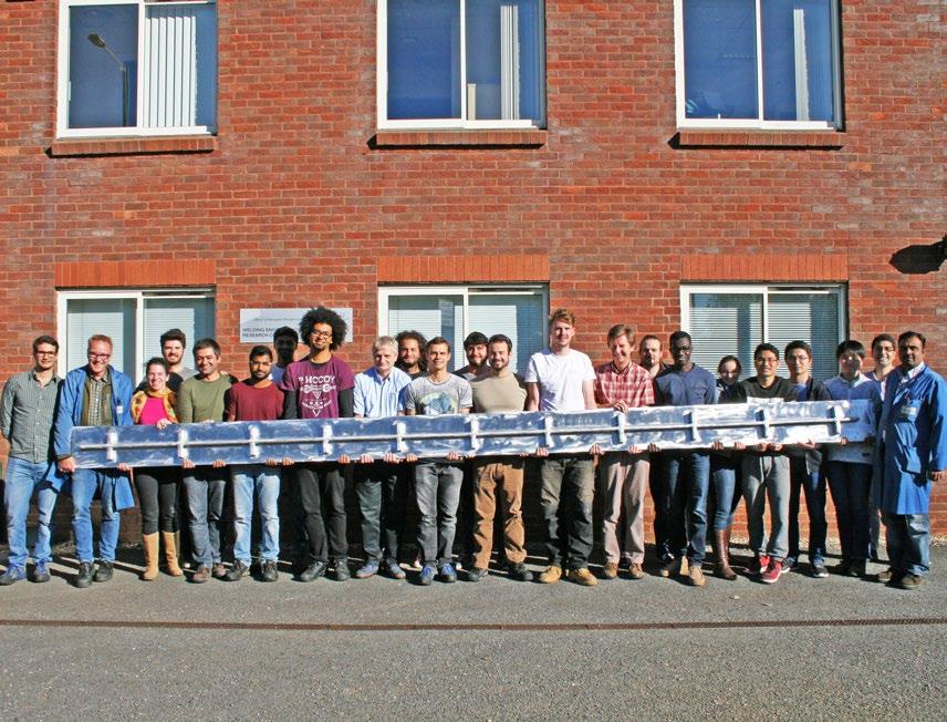
Metal Additive Manufacturing | Winter 2022 93 Vol. 8 No. 4 © 2022 Inovar Communications Ltd | contents | news | events | advertisers | print sub | e-newsletter | GETPDF
WAAM3D: the rise of wire-based AM
Fig. 9 Front and ¾ views of RoboWAAM Advanced. The 'heart' unit features a large 2 x 2 x 2 m deposition cuboid, delivered by a reconfigurable 6-axis robot / 2-axis manipulator combination. It includes WAAM3D’s proprietary FMSTM for deposition environment automatic control (fume treatment but also argon levels). The 'head' unit features the Control Centre, external bulk wire storage accommodating large spools or drums, and all control electronics
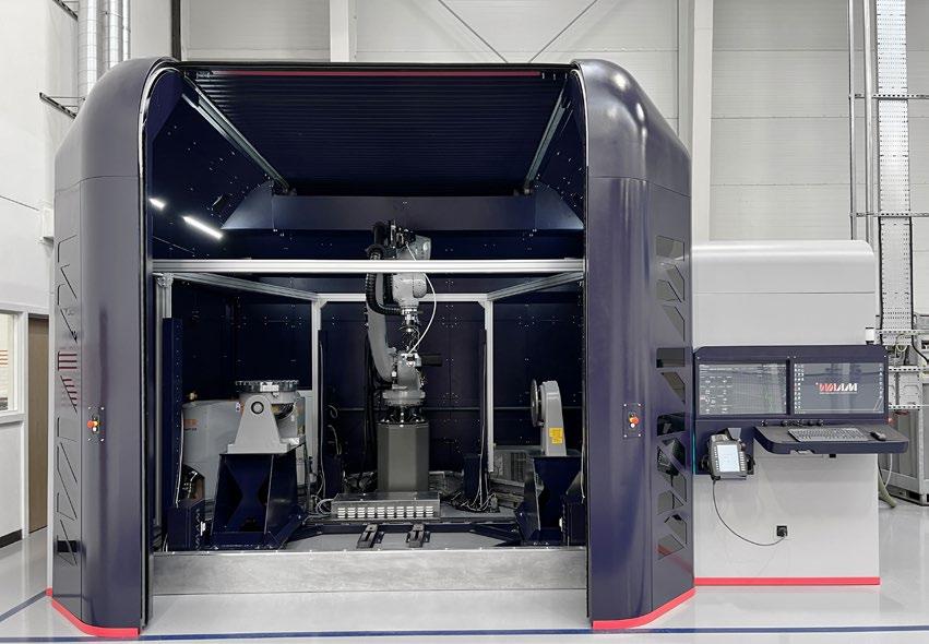
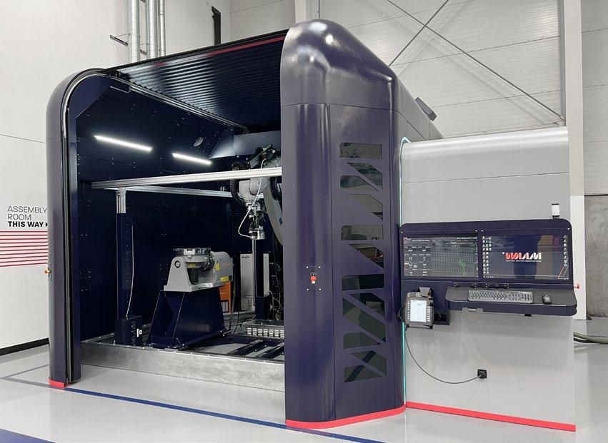
The breadth of software was being broadened, but this had to be underpinned by a comparable improvement in the hardware capability. Since the creation of the basic WAAM3D system described early on, it now features a long list of core and accessory hardware solutions, ranging from new sensors to improvements to automation aspects. A case in point is ShapeTechTM, which is perhaps the most awaited feature: a laser interferometer intervenes right behind a live melt pool, extracting the layer height and the profile of the deposited structure, instantaneously. Also, the Fume Management System (FMSTM), which inexpensively offers the capability to establish and maintain an inert argon atmosphere, whilst containing and filtering all fumes.
What is next for DED-Arc?
The WAAMMat consortium was officially launched in 2012 [11], as a rolling technology development programme at Cranfield University. It comprises of a series of individual projects and activities that were brought together under one umbrella programme. Each of these projects or activities has its own individual objectives and is continually evolving, with mixed funding coming from industry, agencies, and the partnering universities themselves. To date, approximately £10 million has been invested in activities from technology readiness levels (TRL) 1 to 5, with another £5 million of planned future funding activities at Cranfield University, the University of Manchester, Coventry University, and the University of Strathclyde. WAAM3D Ltd took over the higher TRL activities from 2018 onwards.
So, what is today’s academic focus for DED-Arc? The challenge set out by the regulators is clear: the production of high-integrity parts by an unsupervised, robust manufacturing process. Additionally, DED-Arc needs to answer the question of how the process be applied to as many parts as possible. The answer to both
Metal Additive Manufacturing | Winter 2022 94 © 2022 Inovar Communications Ltd Vol. 8 No. 4 | contents | news | events | advertisers | print sub | e-newsletter |
WAAM3D: the rise of wire-based AM
“...one of the challenges for AM is that geometry and properties are produced at the same time. However, with the above framework – that is firmly grounded in physics and material science – combined with novel sensing hardware, the time and cost required to qualify a component can be dramatically reduced.”
these requirements lies in on-board process validation, in-process coldwork, and increased productivity.
On-board process validation
One of the limits of part qualification today is the extensive mechanical testing campaign required to demonstrate compliance of a component on a geometry-by-geometry basis. A more flexible framework is needed:
• Firstly, the relationship between the thermal field experienced in a location, and the resulting microstructure and mechanical properties, must be established upfront
• Secondly, an acceptable range of thermal fields that would give acceptable mechanical properties must be identified
• Thirdly, an FEA simulation needs to be run on the target geometry, based on its set of process parameters and the DED-Arc toolpath plan, to uncover potential regions of expected criticality (i.e., where the thermal field might be out of the qualified band). If necessary, corrections to process parameters and the DED-Arc toolpath plan can be undertaken at this point to address any issues
• Finally, when the geometry is being deposited, advanced sensors are needed to demonstrate that the thermal field experienced during deposition is indeed the qualified one, location by location
As previously mentioned, one of the challenges for AM is that geometry and properties are produced at the same time. However, with the above framework – firmly grounded in physics and material science – combined with novel sensing hardware, the time and cost required to qualify a component can be dramatically reduced.
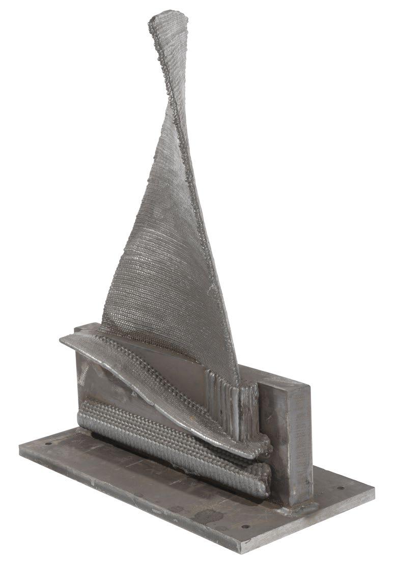
In-process cold-work
It shouldn’t come as a surprise that alloys designed to be thermo-
Fig. 10 A 1 m tall steel industrial gas turbine blade, built in 2013 at Cranfield University for GE Power and Water, in the as-built condition. The part was deposited using multi-orientation and multi-hierarchical approaches, in a variety of different alloys (Courtesy Cranfield University and GE Power and Water)
mechanically processed do not give of their best when the mechanical aspect is missing. To address this, Cranfield University has been investigating the addition of in-process cold-work via rolling or peening methods since 2010. This was initially to control residual stress in welded structures, and later to refine microstructures in DED-Arc deposits. The alternation between additive and cold-work passes has been a phenomenal tool to increase the mechanical performance of a growing list of alloys of titanium, nickel,
aluminium, iron, tantalum, Ti-6Al-4V, maraging steel, superalloy 718, Al-Mg-Sc, and others. These chemistries are now showing a forged level of mechanical properties.
Increased productivity
More and more environmental analyses are showing that DED-Arc is the better choice from both embodied energy and CO 2 standpoints. However, especially for materials of relatively low value, cost can remain in favour of traditional technologies, with the deposition rate being the
Metal Additive Manufacturing | Winter 2022 95 Vol. 8 No. 4 © 2022 Inovar Communications Ltd | contents | news | events | advertisers | print sub | e-newsletter | GETPDF
WAAM3D: the rise of wire-based AM
dominant driver. Judging by publicly available information (both academic and commercial), the predominant choice is still to rely on welding power sources and processes, which, whilst well established and readily available, do have tangible limits when used in an additive context.
Cranfield and WAAM3D are working in partnership on two fronts: developing radically new approaches to delivering energy and controlling the resulting melt pool. The first, based on the hybridisation of lasers and electric arcs, is to increase deposition rates, overcome the limitations of single axisymmetric heat sources and achieve independent control of layer height and wall width.
The second, that is much closer to commercialisation [12], leverages on multiple asynchronous wire feeds to achieve increased process efficiency, delivering substantially higher deposition rates, fully independent material and energy feed rates, and full thermal and geometry control. For the latter, compared to metal inert/active gas processes, the increases in deposition speed have been measured as being as high as 10 X for some materials, making the exploration of wider horizons of economic feasibility a much more realistic prospect.
Fig. 11 A 1 m tall Ti-6Al-4V
in 2017 at Cranfield University
Alenia
in the as-built condition. The part delivered 80% material savings, 40% cost savings and potentially 65% lead time savings compared to the previous manufacturing route. Before as well as after machining, the part was CT-scanned and ultrasonically inspected, satisfying all technical and quality requirements (Courtesy Cranfield University and Thales Alenia Space)
Outside Cranfield University, it is worth mentioning other institutions that have contributed on both the academic and industrialisation fronts. Work at Oak Ridge National Laboratory (ORNL), USA has been on-going for several years, focusing on material science and computational modelling to assist industrial part building. They have recently demonstrated viability of multirobot deposition to increase part size and deposition rates. After his tenure at Cranfield University, Prof. Norrish continued his research at the University of Wollongong, Australia, focusing on robotic DED-Arc. The group has published vast amounts on residual stress characterisation, material and mechanical properties characterisation, process developments, and CAM software, amongst several other areas of activity.
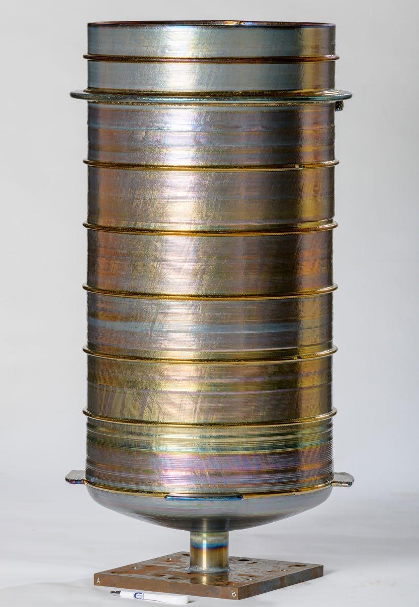
Metal Additive Manufacturing | Winter 2022 96 © 2022 Inovar Communications Ltd Vol. 8 No. 4 | contents | news | events | advertisers | print sub | e-newsletter | WAAM3D: the rise of wire-based AM
“Whilst DED-Arc today is still a few years behind powder-based AM in terms of broader industrial adoption, it undoubtably has huge potential to revolutionise the manufacture of metal parts, possibly even more than powderbased AM technologies.”
pressure vessel for space exploration, built
for Thales
Space,
Applications overview
A recent article published by a team at NASA [13] recaps the rules to match processes and applications properly. It is an excellent starting point, although with the field moving rapidly, we must constantly reassess where to look to extract DED-Arc’s fullest potential. Based on the points summarised in this article, it should not surprise that, to date, typical applications have been:
• Frame structures for the aerospace sector, with Ti-6Al-4V being the predominant alloy
• Pressure vessels and other rotational geometries, in Ti-6Al-4V but also nickel-base alloys, also for aerospace
• Flanges, elbows, connectors and other components in carbon steel and nickel-base alloys for the energy sector
• Propellers and other bronze parts, for the marine and related industries
• Tools, dies and moulds, made ex-novo but also repaired
In general, parts made with relatively cheap alloys benefit from better management of inventory and lead times, as well as supply chain flexibility. Additionally, parts made with relatively expensive alloys benefit from financial savings related to reduced material consumption.
DED-Arc has the potential to revolutionise manufacturing
For a long time seen as the less sexy branch of metal AM, DED-Arc has been confined to a few laboratories. However, those working on it have kept pushing the boundaries of what is possible, gaining larger and larger industrial traction and opening novel market segments. Crucially, these are not just around hardware, but also for the much-required software packages, as well as materials. DED-Arc has now grown to embrace a vibrant
global ecosystem of universities, spin outs, and scale ups.
Whilst DED-Arc today is still a few years behind powder-based AM in terms of broader industrial adoption, it undoubtably has huge potential to revolutionise the manufacture of metal parts, possibly even more than powder-based AM technologies.
It is a matter of time, effort, and errors. However, in the nottoo-distant future, we will be remembering the struggles at the beginning of this century with a smile, whilst flying the world in planes, exploring the seas in vessels, and visiting Mars in rockets – all containing components made by DED-Arc.
Contact
Filomeno Martina CEO and co-founder, WAAM3D 5 Thornton Chase, Milton Keynes, MK14 6FD, UK info@waam3d.com www.waam3d.com
References and footnotes
[1] BS EN ISO ASTM 52900 2021
[2] A registered trademark of WAAM3D Limited, application number UK00003147979, UKIPO; and 017992080, EUIPO
[3] R Acheson: ‘Automatic welding apparatus for weld build-up and method of achieving weld build-up’; US patent no. 4 952 769 1990
[4] R Baker: ‘Method of making decorative articles’; US patent no. 1 533 300 1925
[5] https://patents.google.com/ patent/US1533300A/en
[6] Ribeiro, Fernando & Norrish, John. (1996). Case study of rapid prototyping using robot welding: 'square to round' shape
[7] Martina and Williams, 2015. Wire+arc additive manufacturing vs. traditional machining from solid: a cost comparison, Cranfield University
WAAM3D: the rise of wire-based AM
[8] This ‘break-even’ point depends mostly on material cost and deposition rate, and it changes from alloy to alloy
[9] Pickin et al.: ‘Control of weld composition when welding Al alloy’, Science and Technology of Welding and Joining, 2009, 14 (8), 734-739
[10] Marinelli et al.: ‘Functionally graded structures of refractory metals by wire arc additive manufacturing’, Science and Technology of Welding and Joining, 2019, 24 (5), 495-503
[11] Wire Arc Additive Manufacturing Maturation, www.waammat.com [12] www.waam3d.com/projects/ HPWAAM ; www.waam3d.com/ projects/LAMM
[13] Gradl et al.: ‘Robust Metal Additive Manufacturing Process Selection and Development for Aerospace Components’, Journal of Materials Engineering and Performance, 2022, 31, 6013–6044.
Metal Additive Manufacturing | Winter 2022 97 Vol. 8 No. 4 © 2022 Inovar Communications Ltd | contents | news | events | advertisers | print sub | e-newsletter | GETPDF


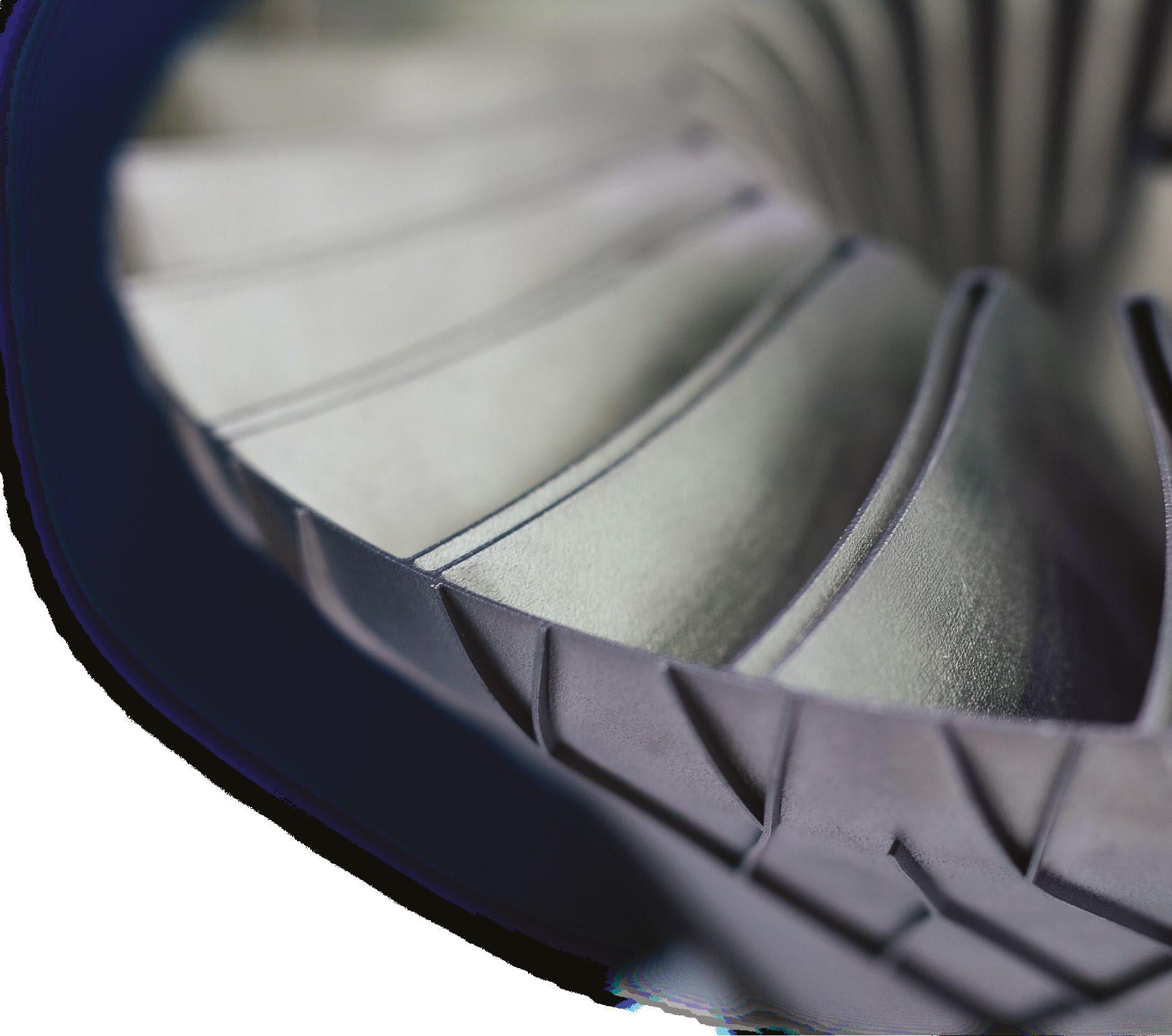
MAY 2-4, 2023 McCormick Place | Chicago NORTH AMERICA’S LARGEST AND MOST INFLUENTIAL ADDITIVE MANUFACTURING EVENT. EXPERIENCE THE NEXT LEVEL OF ADDITIVE MANUFACTURING IN CHICAGO. REGISTRATION IS OPEN rapid3devent.com Witness groundbreaking product announcements, experience hands-on equipment demos, learn real-world additive manufacturing applications from the most respected experts, and network with thousands of industry peers.
Smart sensor-integrated parts by AM: A look at a novel possibility with industrial applications
Additive Manufacturing processes offer a high degree of design freedom. The Laser Beam Powder Bed Fusion of metals (PBF-LB/M), in particular, has established itself for series applications of complex-shaped parts in numerous industries. In this article, Prof Dr-Ing Christian Seidel considers the next major step in PBF-LB, which could offer designers unknown potential: the production of sensor-integrated AM parts. Methods and solutions for the manufacturing of sensor-integrated AM parts are presented and industry-relevant case studies showcased, illustrating the potential offered by sensor-integrated ‘smart parts.'
Product developers appreciate AM because it offers a high degree of design freedom. For instance, the topology of a component in the force flow can be optimised according to the loads occurring, and the result can be ‘printed’ more or less directly. A well-known application for this capability is in aircraft brackets made of titanium alloys. The possibility of function integration has also been exploited in numerous industries, since, with AM, solid-state joints or porous structures can be manufactured in a targeted manner.
On top of these applications, several examples can be seen where sensors were implemented manually by operators during the build process. The resulting sensor-integrated parts are also referred to as ‘smart parts.’ Additive Manufacturing technologies are particularly suitable for such parts, since the principle of layer-on-layer manufacturing allows sensors to be integrated close to the desired measuring point, even in parts with complex geometries.
Current fast-growing digital trends, such as condition monitoring and predictive maintenance, are increasing the pressure on Additive Manufacturing technologies to be able to produce smart parts whose condition can be monitored
by sensors. In this way, maintenance intervals can be minimised and components proactively replaced, even before their technical failure. To realise the AM of such sensorintegrated smart parts, two main challenges must be solved:
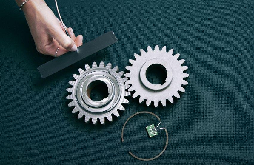
IGCV allowing for superior condition monitoring (left), conventional gear (right), additively manufactured antenna and sensor that has been implemented inside the smart gear (bottom), and reading unit for the RFID-based sensor (top)
Fig. 1 Sensor-integrated smart gear
Metal Additive Manufacturing | Winter 2022 99 Vol. 8 No. 4 © 2022 Inovar Communications Ltd | contents | news | events | advertisers | print sub | e-newsletter | GETPDF Smart sensor-integrated parts
produced by Fraunhofer
1. The build process needs to be modified to allow for sensor handling

2. The sensors need to be able to withstand the thermal loads that occur during the build, and must be fully functional downstream of the integration
Possibilities for integrating sensors during the Powder Bed Fusion process
Following Binder, et al. [1], three different approaches are known for integrating sensors during PBF-LB (Fig. 2):
1. Manual insertion of sensors
2. Automated insertion of sensors


3. Direct manufacturing of sensors, for example by means of a multimaterial mechanism
Each approach has its strengths and weaknesses. Manual sensor integration has disadvantages compared to an automated solution, as the integration times are much higher and operator expertise is needed. In addition, loss of part quality and reproducibility must be avoided, which is a challenge because, typically, the inert gas atmosphere must be interrupted to manually insert the
sensors into the part. However, no additional machine components are needed for the manual process.
The most elegant way to fabricate a smart part is to build the sensors via PBF-LB within the build chamber. Using this method, no additional sensors need to be handled. One way this can be achieved is by processing multiple materials within a single build. However, this concept still has limited maturity, and more research is required before it can be tested and determined to what extent direct sensor production is possible on an industrial scale.
Fig. 3 illustrates an automated sensor integration process. The images were captured in the laboratory of Fraunhofer IGCV in Augsburg, Germany. To achieve the automated sensor integration, an AconityOne metal PBF-LB machine (Aconity3D GmbH, Herzogenrath, Germany) was modified to allow for a pick-and-place unit to be used within the build chamber; this additional hardware was integrated into the AconityOne and can also be controlled by the machine software. The layer-on-layer build job can be interrupted in a defined layer (steps 2-7 in Fig. 3) to allow for automated sensor integration without losing the protective gas atmosphere.
Weldable Strain gauges (WSG) are used to monitor mechanical force, such as compression and strain. Typically, WSGs are fixed to the surface of the part by glued or weld-on bonding. This conventional approach has crucial disadvantages: a WSG mounted on the component surface does not provide any information about the forces inside of the component and is exposed to the surrounding environmental influences.
Due to the layer-on-layer build method of AM parts, sensors can be integrated almost anywhere within the part; therefore, these drawbacks are overcome. But the adhesive bonding typically used presents challenges for many metal AM processes due to their high process temperatures and the curing times of the used glues. Therefore, Binder et al. [2] described a weld-on method for WSG integration where the firm fusion for force transmission is created by applying weld seams between the sensor (WSG) and the AM component. Since welding is the basic principle for PBF-LB, no additional laser source is needed for
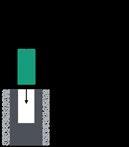
Metal Additive Manufacturing | Winter 2022 100 © 2022 Inovar Communications Ltd Vol. 8 No. 4 | contents | news | events | advertisers | print sub | e-newsletter | Smart sensor-integrated parts
Integration of Weldable Strain Gauges – pilot testing and case study of a probe rake
Process inclusion Integration speed Potential Low Low Low Low By opening the process chamber door Manual sensor integration Manufacturing
sensor integration Via glovebox High High High High Maturity level Flexibility
Fig.
2 Comparison of different methods for integrating
sensors in Powder Bed Fusion technologies (Courtesy Binder et al. [1])
of sensor via LPBF Automated
the spot welding required to connect the WSG with the part.
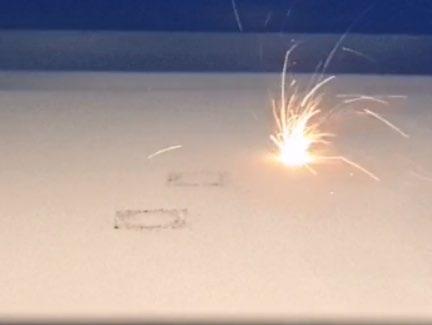
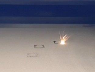
For handling the WSGs, Binder et al. [2] used manual integration, as the system shown in Fig. 3 is not currently optimised for the handling of flexible components such as WSGs.
Fig. 4 (left) shows the as-built tensile test rod with the integrated strain gauge. As can be seen in the measured data (Fig. 4, right), the accuracy

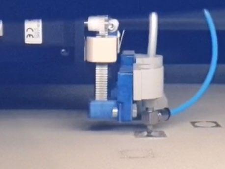
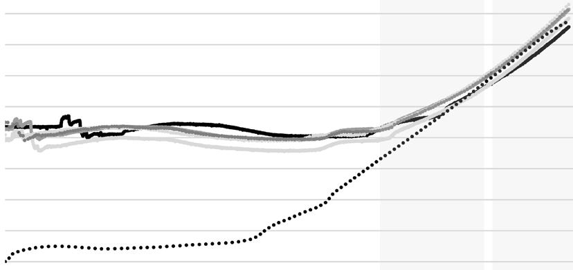
of the WSG is limited until a strain of 0.027%. Starting at 0.027% strain, load detection of the as-built smart tensile rod, compared to the value of the tensile testing machine, is accurate with ca. +/- 5% deviation in measured stress values.
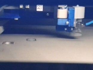
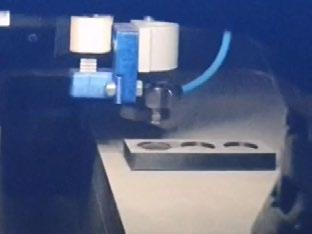
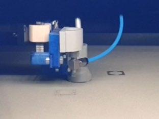
After having proven that the integration of WSGs is possible for basic geometries such as a tensile rod, a case study with a gas flow
probe was performed. Thereby, a ‘probe rake’ provided by Vectoflow GmbH was redesigned and additively manufactured as a smart part. The said component is usually manufactured by the company Vectoflow, without integrated sensors, using PBF-LB. Its function is to measure locally occurring gas flows in a streaming field (e.g., within an aero engine).
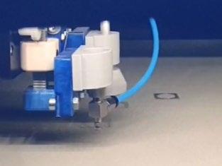
Winter 2022 101 | contents | news | events | advertisers | print sub | e-newsletter | GETPDF ,•···................... - .. - ··· ················· ······ .. .. ... .. .. .. .. .. /" .. Smart sensor-integrated parts
Fig. 3 Automated sensor integration by utilising a vacuum gripper, following Binder et al. [1]: Step 1: building cavity geometry, 2 and 3: vacuum cleaning of cavity, 4: pick sensor from sensor magazine inside the build chamber, 5 and 6: place sensor inside the cleaned cavity, 7: application of a new powder layer, filling the cavity with the sensor, completed, 8: continuation of the main build
(b)
45 Dead zone Synchronizing Load detection Stress in N/mm 2 Strain in % a) b) 0 0.046 Tensile testing machine Test 1 Test 2 Test 3 Test 4 Test 5 0.000 0.001 0.005 0.009 0.012 0.020 0.027 0.034 5 10 15 20 25 30 35 40 1. 2. 3. 4. 8. 5. 6. 7. Strain gauge Tensile testing machine F F
Fig. 4 Weldable strain gauge (WSG) tensile test: (a) Schematic view of the tensile rod with integrated WSG;
Associated graph: the tensile testing machine is shown in dotted line, the 5 times repeated answers of the WSGs in different shades of grey. (Source Binder et al. [2])
Fig. 5 Additive Manufacturing of smart probe rakes with integrated Weldable Strain Gauges (WSGs) to determine occurring vibrations and forces. Case study performed by Fraunhofer IGCV together with Vectoflow GmbH (Source Binder et al. [1])
Due to the surrounding flows, vibrations can also occur on the measurement system, which cannot be detected so far. However, vibration data is an important parameter for both the design of the measurement system and for more detailed testing and analysis of flow fields.
Fig. 5 shows the ‘smart version’ of the probe rake manufactured out of nickel-base alloy IN718. This part was built on an SLM®125

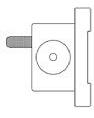
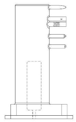

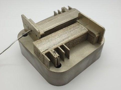
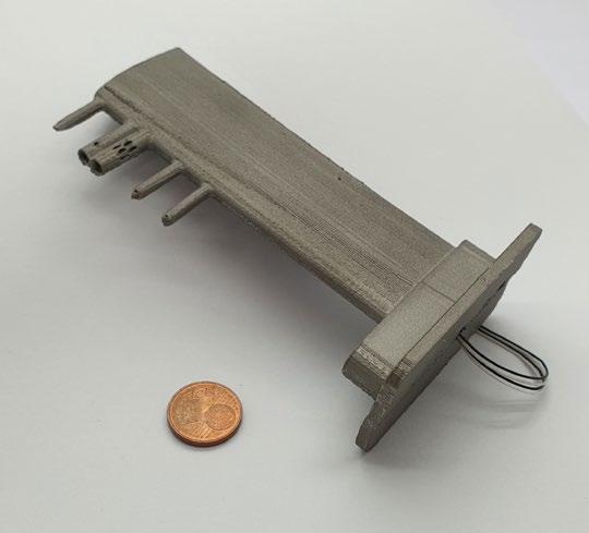
system (SLM Solutions AG, Lübeck, Germany) at Vectoflow GmbH. For the integration of the WSG, the parameter constellation from pilot testing with the tensile rod was used (laser power P L = 150 W, scan speed v s = 200 mm/s, weld width 0.18 mm). Since the WSG requires a cable connection, a cable duct (X-Y plane) was provided, through which the measuring cables of the sensor component are guided
out of the probe rake via the carrier plate.
To evaluate the proper operation of the smart flow rake, a vibration test of the system was performed. The test setup is shown in Fig. 6. An MX840B amplifier was used with a quarter-bridge circuit (350 ohm) at a sampling frequency of 1,200 Hz. A defined frequency of 350 Hz was applied to the flow rake in accordance with the US military standard
Metal Additive Manufacturing | Winter 2022 102 © 2022 Inovar Communications Ltd Vol. 8 No. 4 | contents | news | events | advertisers | print sub | e-newsletter |
6 Test setup for the additively manufactured sensor-integrated smart
rake, focus: determining the accuracy of measurements in terms of vibration and spectral power densities
applied vibration
350 Hz
[1] Pitot-probe | [2] Keel probe (total temperature) | [3] Keel probe (total pressure) | [4] 5-hole probe | [5] 3-hole probe Interruption plane (X-Y) WSG wires WSG wires [1] [2] [3] [4] [5] Support structures Position integrated WSG Probe rakes on build platform Manufactured IN718 probe rake Smart sensor-integrated parts -160 -140 -120 -100 -80 -60 -40 -20 0 0 100 200 300 400 500 -140 -120 -100 -80 -60 -40 -20 0 325 335 345 355 365 3 Power/Frequency in dB/Hz Frequency in Hz Frequency in Hz WSG inside FBG outside BraggMETER FS22DI QuantumX MX840B Turbinevibrator GT6 Pneumatic controller Lab-PC 60 mm FBG WSG Strain Gauge Faser-Bragg-Grating (FBG) Data wiring Pneumatics 1) Pitot-probe 2)Keel probe (total temperature) 4) 5-hole probe 5)3-hole probe 3) Keel probe (total pressure) 1) 2) 3) 4) 5) Test setup Data evaluation
Fig.
flow
under an
of
(Source Binder et al. [1])
Fig. 7 Illustration of the used test gear with a diameter of 118 mm with a focus on the concept of the external antenna in combination with the internal sensor cavity (Source Binder et al. [2])
MIL STD 810 H via a turbine vibrator. The flow rake was then subjected to a test with a defined frequency of 350 Hz. The correctness of the vibration behaviour was ensured by an externally applied Fibre Bragg Grating (FBG) sensor. In this state, the vibrations detected by the strain gauge (WSG) were evaluated and compared with those of the FBG. Fig. 6 shows that the power maxima occurred equally at 350 Hz. This confirms the correct operation of the concept.
Case study: RFID-sensormonitored gear wheel
The probe rake case study showed that implementing sensors with cables is challenging for automation. For that reason, the integration of the WSG was done manually to ease cable handling inside the powder bed. In this case study, radio-frequency identification (RFID)-based sensors are used to monitor a gear wheel. As RFID-sensors do not typically require cables, they are suitable for both manual and automated integration, for example by means of a vacuum gripper. However, several challenges remain, such as: ensuring proper
operation and data transfer of RFID sensors in an electromagnetically shielded metal environment; enabling battery-free operation; and offering sufficient protection against thermal load during the manufacturing process.
By overcoming these challenges, it will be possible to draw conclusions about the lubrication or damage condition of a gear through vibration analysis, but also to record eigen frequencies of the system or the rotation speed of the gear. Within this case study, a straight-toothed type C gear with a tip diameter of 118 mm, a bore diameter of 40 mm, twentyfour teeth and a normal modulus of 4.5 was investigated. The gear is a typical gear test geometry and
is designed for a load of 250 Nm at 3000 rpm, Fig. 7.
Of the RFID technologies, UHF (ultra-high frequency, 868 MHz) provides a high data rate and long reading range (up to 12 m) compared to LF (low frequency, 125 kHz) and HF (high-frequency, 13.56 MHz) with a reading range of few centimetres, making it the most suitable technology for the project. The UHF RFID technology is widespread, so that a large selection of components and infrastructure is available for a corresponding system.
However, as it is known that electromagnetic waves are strongly shielded by metallic components and, compared to LF technologies, which use inductive coupling, are
Metal Additive Manufacturing | Winter 2022 103 Vol. 8 No. 4 © 2022 Inovar Communications Ltd | contents | news | events | advertisers | print sub | e-newsletter | GETPDF
“The probe rake case study showed that implementing sensors with cables is challenging for automation. For that reason, the integration of the WSG was done manually to ease cable handling inside the powder bed.”
Isometric view Side view Sectional view A-A
Antenna Sensor cavity A-A Smart sensor-integrated parts
30
mm
not able to penetrate metal, this is a major obstacle. Therefore, an antenna located on the outside of the gear wheel is to be combined with a well-protected sensor unit positioned inside the gear wheel. In this way, negative shielding effects on the electromagnetic waves can be reduced, and the more powerful UHF technology (longer range, faster transmission rate) can be used.
A dipole antenna was designed on the outside of the gear which matches the circular shape of the part. To be able to measure the acceleration data inside the gear and to protect the electronic printed circuit board (PCB) from environmental influences, such as moisture or oil, a cavity was designed for the sensor
integration. The following components were used and positioned inside the cavity (width: 20 mm, depth: 3.5 mm) to implement the concept:
UF Reader PulsarMX UHF Mid-Range Reader (power transmission: 27 dBm, 500 mW)
KX122 Tri-Axis Accelerometer (Kionix)
• UHF RFID IC: Rocky100 (860960 MHz, ISO18000-6 type C compliant, operating temperature between - 45 and + 85°C)
To ensure sufficient protection against thermal load during the manufacturing process, the cavity design foresees a triangle shaped
closing of the cavity, Fig. 8. As with the case study on the probe rake using WSG, the electrical connection of the PCB was made using the laser in the PBF-LB machine as a spot welder.
After the gear wheel was additively manufactured, and the powder removed, contour conforming wire electrical discharge machining was used to separate part and build plate, and the foreseen cavities were filled with an insulating material by casting. As part of the validation process, a CT scan verified that the electrical contact between the antenna and the RFID transponder was successful and that the position of the integrated circuit board was maintained even after casting and curing of the insulation matrix.
Subsequently, the function of the sensor-monitored gear was ensured by checking the readability of the data. At a distance of 1 cm between the reader and the gear wheel, the data can be read out reliably, even when the gear wheel is rotating. The gear wheel was rotated at approx. 360°/minute and the resulting wirelessly transmitted values were read out.
In summary, the gear wheel case study demonstrated how a smart gear wheel can be produced by designing a UHF RFID antenna and extending the standard AM process. This approach offers great potential for industrial applications and, at the same time, hardly influences build time and manufacturing costs. Nevertheless, specific challenges remain to be investigated on a case-by-case basis before industrial adoption.
Post-heat treatment: Current PCB can typically not withstand thermal loads of over 600°C. This can become a challenge if, for example, stress relief annealing, or other material-specific heat treatment routines are required.
Data transmission rate: To enable vibration monitoring of the component in the future, it is beneficial to record and transmit vibrations at a higher frequency.
Metal Additive Manufacturing | Winter 2022 104 © 2022 Inovar Communications Ltd Vol. 8 No. 4 | contents | news | events | advertisers | print sub | e-newsletter |
Fig. 8 Sectional view through the cavity of the gear wheel during the build-up process (Source Binder et al. [2])
“...the gear wheel case study demonstrated how a smart gear wheel can be produced by designing a UHF RFID antenna and extending the standard AM process. This approach offers great potential for industrial applications and, at the same time, hardly influences build time and manufacturing costs.”
59
AM
PCB Electrical
Temperature
triangle filled with powder Support area (CNC-machined in post-process) Smart sensor-integrated parts
Pouring hole Build-up direction
mm Interruption layer
conductor track Antenna (16MnCr5)
connection
protective closure
While the system presented in this work is capable of transmitting data at a frequency of 1–2 Hz, for vibration measurement it is desirable to be able to resolve vibrations at, for example, > 1,000 Hz, otherwise relevant high-frequency vibration changes might not be resolved. Initial approaches for overcoming this challenge are already available but need to be verified for the specific industrial application.
Reading distance:
The maximum readout range within this case study was less than expected at ~1 cm instead of the desired range of several meters. This is probably due to the electromagnetic field influencing the metal environment and the rather low achievable gain of the antenna. Specific investigations on antenna design and performance are recommended.
Conclusion
The layer-on-layer build-up concept of Additive Manufacturing enables the production of complex geometries. In addition, process interruptions during the build process can allow sensors to be inserted into components, turning them into so-called ‘smart parts.’ Compared to manufacturing technologies such as milling, casting or forming, there are hardly any restrictions regarding the positioning of the sensors, which allows excellent possibilities for applications such as condition monitoring.
This paper outlined three possible methods for sensor integration:
1. Manual integration
2. Automated integration
3. Direct AM of sensors in the part (e.g., through multi-material processing)
Today, manual integration is especially beneficial when sensors with cables, such as the WSGs in this article, must be used in powder bed-based processes. Today, these form-labile components can’t be inserted automatically
in a process-safe manner. RFID technology-based sensors are formstable and can be handled well using, for example, vacuum gripping technology. Therefore, they can be inserted manually or automatically using the approach described within this contribution. However, to ensure proper function during operation, it must be ensured that the measurement signals of the RFID sensors can pass through the metal component. In the example shown, this was achieved by means of an additively manufactured antenna.
The advantage of automated sensor integration is that the inert gas atmosphere in the build chamber does not have to be interrupted and, in general, the insertion process takes only a few seconds. This means that producing ‘smart parts’ extends the machine operating time only marginally, whereas the functionality of the built components can be significantly increased.
It can, therefore, be assumed that sensor-integrated and additively manufactured components hold great potential that has yet to be tapped at present. With the current state of knowledge, this potential can be exploited. Since there are currently no commercial machines available on the market that enable the AM of sensorintegrated components, targeted collaboration between researchers, machine manufacturers and users will be required in the coming years to leverage this potential.
Acknowledgement
The author expresses his sincere thanks to the Free State of Bavaria and its Bavarian Ministry of Economic Affairs, Regional Development and Energy for funding the MULTIMATERIAL-Zentrum Augsburg (Multi-material Centre Augsburg). Furthermore, the author thanks Maximilian Binder, Thomas Bareth and Veronika Stapff for their valuable contributions.
References
[1] Binder, M, Dirnhofer, C, Kindermann, P, Horn, M, Schmitt, M, Anstaett, C, Schlick G, Seidel, C, Reinhart, G, ‘Procedure and Validation of the Implementation of Automated Sensor Integration Kinematics in an LPBF System,’ Procedia CIRP, Volume 93, 2020, pp. 1304-1309, https://doi. org/10.1016/j.procir.2020.04.090
[2] Binder, M, Fischer, M, Dietrich, S, Seidel, C, Reinhart, G, ‘Integration of Strain Gauges in Components Manufactured by Laser-Based Powder Bed Fusion,’ Proceedings of the Machining Innovations Conference (MIC) 2020, https:// papers.ssrn.com/sol3/papers. cfm?abstract_id=3724097
[3] Binder, M, Machnik, A, Bosch, M, Kreitz, K, Schlick, G, Seidel, C, ‘In-situ Integration of Weldable Strain Gauges in Components Manufactured by Laser-Based Powder Bed Fusion,’ Proceedings of the 33 rd Annual International Solid Freeform Fabrication Symposiom 2022, pp. 1878-1894
[4] Binder, M, Stapff, V, Heinig, A, Schmitt, M, Seidel, C, Reinhart, G, ‘Additive manufacturing of a passive, sensor-monitored 16MnCr5 steel gear incorporating a wireless signal transmission system,’ Procedia CIRP, Volume 107, 2022, pp. 505-510, https://doi.org/10.1016/j. procir.2022.05.016
Author
Prof Dr-Ing Christian Seidel christian.seidel@igcv.fraunhofer.de christian.seidel@hm.edu
Christian Seidel is a Full Professor for Manufacturing Technologies and Additive Manufacturing Processes and Head of Smart Manufacturing Lab at Munich University of Applied Sciences. In addition, he serves as Head of Additive Manufacturing Research at Fraunhofer IGCV (Augsburg/Munich). Furthermore, he holds several positions in both academic and industrial networks.
Metal Additive Manufacturing | Winter 2022 105 Vol. 8 No. 4 © 2022 Inovar Communications Ltd | contents | news | events | advertisers | print sub | e-newsletter | GETPDF
Smart sensor-integrated parts


ADDITIVE MANUFACTURING USERS GROUP Hilton Chicago Chicago, Illinois USA
Tailored materials for AM:
How a 'powder kit' can achieve greater material diversity with fewer resources in PBF-LB
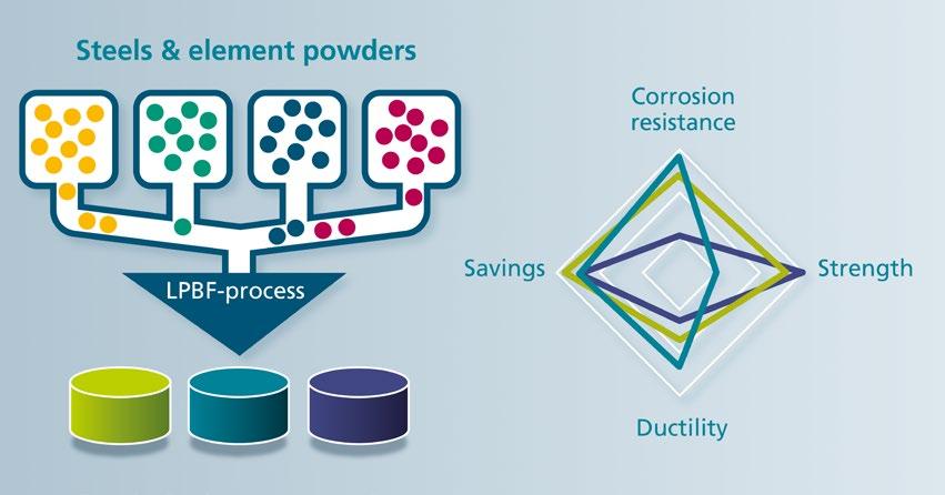
The use of metal AM is ramping up, and so, as a result, is the demand for metal powders. However, the variety of materials available remains relatively small. This is due, among other things, to the exacting requirements for the powders used, and the method of production. In addition, the production of smaller quantities of powder can be uneconomical. In a project funded by the AiF, the IWM at Germany’s
RWTH Aachen University and Fraunhofer IFAM have developed a sustainable 'powder kit' for the individual and robust production of metal powder mixtures with subsequent alloying during PBF-LB processing. The partners share their progress.
Additive Manufacturing offers many advantages and allows maximum design freedom in the design and production of components. These advantages have enabled AM technologies to become well established in fields such as automotive or aerospace. However, the fields of application for AM require not only the best possible designed geometry, but also optimised material properties. This requires an appropriately adapted material.
In conventional, subtractive production processes, there are hundreds of different steels, aluminium alloys, wear-resistant cobalt-chrome alloys and more for each specific application. In AM, the choice across all metallic materials is limited to less than thirty materials, so not all requirements can be covered. The central idea of this project was to cover as many material properties as possible with a small selection of powders that are mixed in varying proportions as required.
Commonly required material properties include corrosion resistance, strength, hardness and thermal conductivity. Many steel alloys consist of the same elements, such as carbon, chromium and nickel, but
differ in the respective proportions. With the aid of the ‘LPBF Powder Building Kit,’ the user can select the appropriate powders by entering the desired property profile and mix them in the specific quantity ratio. The concept is shown in Fig. 1. One type of material used for special applications are duplex steels, which combine high strength with high toughness due to their typical
Metal Additive Manufacturing | Winter 2022 107 Vol. 8 No. 4 © 2022 Inovar Communications Ltd | contents | news | events | advertisers | print sub | e-newsletter | GETPDF A powder toolkit for PBF-LB
The right elements ensure a high diversity of material properties
Fig. 1 Concept of the PBF-LB powder building kit (Courtesy Fraunhofer IFAM)
PBF-LB process
Name 1.4462 (D2205) 1.4404 (316L) CrN Mo Cr
60:30:2:2:6 (D1) 60.00 30.00 2.00 2.00 6.00 75:18:2:5 (D2) 75.00 18.00 2.00 - 5.00
Table 1 Mixing ratio of blends in wt.%
Name C Cr Mo Ni N Si Mn
1.4462 (D2205) ≤ 0.03 22.00 3.00 5.25 0.16 ≤ 1.00 ≤ 2.00 1.4404 (316L) ≤ 0.03 17.50 2.50 12.50 - 1.00 2.00 CrN - 78.8 - - 21.2 -Cr - - - 100 - -Mo - - 100 - - -60:30:2:2:6 (D1) 0.02 26.03 4.48 6.75 0.54 0.45 0.9 75:18:2:5 (D2) 0.02 26.20 2.66 6.20 0.55 0.47 0.9 1.4501 ≤ 0.03 25 3.5 7 0.25 ≤ 1 ≤1
Table 2 Calculated chemical composition of utilised base steels and the powder mixtures in wt.%
Name D10 [µm] D50 [µm] D90 [µm]
1.4462 (D2205) 28.3 43.5 62.1 1.4404 (316L) 20.7 35.8 54.3 CrN 21.8 59.7 99.0 Cr 21.0 37.2 54.0 Mo 5.6 15.5 38.3 60:30:2:2:6 (D1) 23.6 41.9 61.7 75:18:2:5 (D2) 25.0 40.9 59.3
Table 3 The particle size distributions of the utilised powders
austenite-ferrite mixed structure. Super duplex steels have increased contents of chromium, molybdenum and nitrogen to achieve seawater resistance [1].
In this work, the corrosion behaviour of specimens prepared by PBF-LB and tailored super duplex steel powder blends is investigated. The goal of these powder blends is to tailor the configuration of specific component properties by adding elemental powders to a base powder. It is possible to additively manufacture and modify the properties of steel alloys using commercially available element powders and master alloys. Due to the high energy input of the laser beam into the material, which heats it above the liquidus
temperature, it is possible to produce alloys within the PBF-LB process via melting [2]. By varying elemental powders (powder construction kit), the component developer is no longer dependent on a narrow portfolio of powder suppliers, but can select individually and produce their own alloys and material properties.
The laser beam-based processing of elemental powders enables design freedom in combination with material diversity. The approach of processing elemental powders by laser cladding (DED) is widely used because no segregation problems can occur in the powder bed. However, the geometric flexibility and accuracy of this process is limited compared to PBF-LB. Examples of important
research are the production of stainless steels X2CrNiMo17-12-2 and X14CrMoS17 (430L) [3], elemental powder DED for rapid material developments [4] or developments for graded steels [5]. Previous publications on this research project have shown that segregation of powder mixtures in PBF-based AM processes is low if certain parameters and methods are used [6].
Materials and methods
Powders & parts
Two duplex alloy compositions (D1 & D2) – similar to a standard corrosion resistant super duplex steel (1.4501) – were chosen and realised by blending four and five commercially available powders, respectively. The alloys are based on 1.4462 and modified by additions of 1.4404, Cr, CrN and Mo. All powders have a spherical shape whereas the CrN powder is mechanically crushed with an irregular shape. The mixing ration of the two alloys can be found in Table 1.
The mixing duration and methodology was selected based on prior works [6]. According to these, the Turbula mixer (three-dimensional shaking mixing) provides sufficient mixing of the powder after a mixing time of fifteen minutes. The blends ‘60:30:2:2:6’ and ‘75:18:2:5’ were blended for thirty minutes. The alloying content of the powders and the calculated composition from the mixing ratio is listed in Table 2. The nominal composition of 1.4501 is provided for comparison.
According to Shenoy, the influence of particle size is considered the most important concerning segregation [7]. The publication prior to this work confirmed the conclusions [6]. The particle size distribution of the powders used for the blends in this work were determined by a particle size measuring device from Beckman Coulter LS. The particle size distributions of the utilised powders are provided in Table 3. The mechanically crushed CrN powder is slightly coarser than the 1.4462 and 1.4404, while the Mo powder is finer.
Metal Additive Manufacturing | Winter 2022 108 © 2022 Inovar Communications Ltd Vol. 8 No. 4 | contents | news | events | advertisers | print sub | e-newsletter |
A powder toolkit for PBF-LB
Fig. 2 SEM + EDX images of powder blend D1 (60:30:2:2:6)
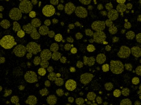
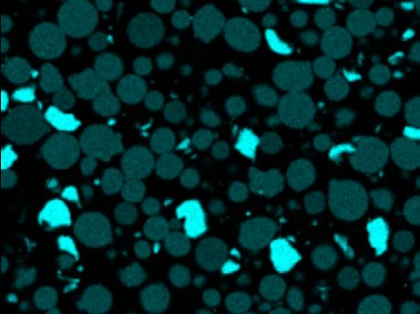
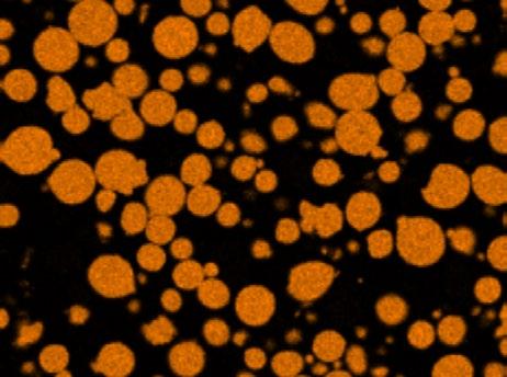
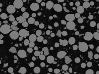
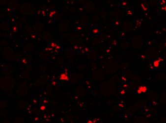
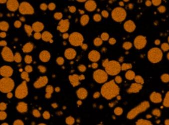
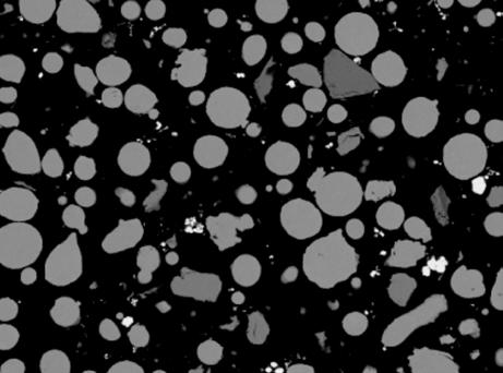
The SEM and EDX images identify the different elements on a qualitative basis. Fig. 2 shows that the blended elements can be found well distributed across the screened scene of D1. Furthermore, it confirms that the Mo powder is much finer than the others. Fig. 3 helps to identify the elements of D2. There is no Mo element powder, therefore the Ni analysis is illustrated, which helps to distinguish the 1.4462 from the 1.4404. The brighter green particles contain higher Ni, which identifies them as 1.4404.
The materials (1.4462; D1; D2) were processed on a Trumpf TruPrint 1000 with a laser beam focus of 30 μm. The parameters were fixed for all samples: a laser power of 195 W, a scan speed of 800 mm s -1 and a hatch distance of 50 μm. In combination with a layer thickness of 40 μm, an energy density of 122 J mm 3 results for manufacturing these parts. Two build jobs were manufactured, one for the tensile specimen in X and Z directions and one for cubes (10 x 10 x 10 mm) and a plate (50 x 10 x 1 mm) for the corrosion tests.
In the following, half of the specimens of each blend received a diffusion annealing (DA) at 1270°C for 2 h. Afterwards, each specimen including the ones from diffusion annealing were solution annealed (SA) in respect to their specific alloy
composition. The temperatures were calculated by Thermocalc [8], which recommended 1060°C for steel 1.4462, 1070°C for D1 and 1120°C for D2.
Blend and part analysis
For mixture D1, a quantitative wet chemical analysis was performed to determine the actual chemical composition of the mixture and to verify the calculated values. EDX analysis was performed to investigate the composition of the parts. Since super duplex steels are intended for corrosive environments, they are inherently very resistant. Therefore, the mixtures were analysed using a current density potential curve. Tests
were performed using a 3.5% NaCl solution at room temperature. The surface of each specimen was ground and polished.
Parts made from the base powder 1.4462 and purchased conventionally manufactured parts made from 1.4662 and 1.4501 were compared with the blends as a reference. Tensile tests were performed at room temperature with B4x20 specimens according to DIN 50125. Only specimens of D1 and D2 were tested in the solution-annealed condition and compared with values of 1.4501 from the literature. In addition, the three specimens were prepared in the horizontal (X) or vertical (Z) direction. An overview can be found in Table 4.
(conventional)
Fig. 3 SEM + EDX images of powder blend D2 (75:18:2:5) Table 4 Specimen analysis overview
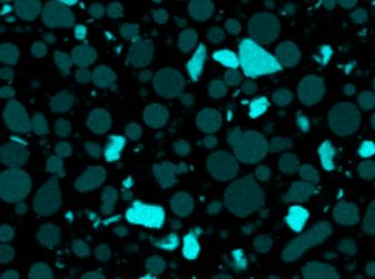
Metal Additive Manufacturing | Winter 2022 109 Vol. 8 No. 4 © 2022 Inovar Communications Ltd | contents | news | events | advertisers | print sub | e-newsletter | GETPDF
SEM Fe Cr Mo
SEM Fe Cr Mo
SEM Fe Cr Mo SEM Fe Cr Mo
Analysis Diffusion annealed Solution annealed Curr. density/ pot. curve Tensile Tests D1 part (PBF-LB + SA) - X X X D1 part (PBF-LB + DA + SA) X X XD2 part (PBF-LB + SA) - X X X D2 part (PBF-LB + DA + SA) X X X1.4462 (PBF-LB + SA) - X X1.4462
DA + SA) X X X1.4462
- - X
1.4501
- - X
A powder toolkit for PBF-LB
(PBF-LB +
(conventional)
-
-
Results
Wet chemical analysis
The values resulting from the wet chemical analysis are shown in Table 5. It shows that the actual values for Cr, Mo, Mn and Si are slightly higher. The content of Ni is slightly lower. The N content is 50% lower than calculated, which may be related to the solubility of nitrogen in iron [9]. The higher Cr content may be due to a slightly incorrect amount of the ingredients used for the blend.
Composition of PBF-LB parts
The EDX measurement results are shown in Table 6 and Table 7. The measured and calculated powder compositions are given in each case for reference. Several different positions were analysed (Figs. 4 and 5). As shown, all values are very similar to the powder values from the wet chemical analysis. Cr is again slightly elevated, while the other elements are very close to their individual target values. As mentioned
earlier, this may be due to the slightly incorrect amount of ingredients used for the blend. The results suggest that the various powders, including the elemental ones, are well fused and largely homogeneously distributed in the volume of the sample. This also confirms the results of the wet chemical analysis of mixture D1.
Figs. 4 and 5 show an area of about 120 x 120 μ m 2, corresponding to four scan vectors of the laser. A few non-melted particles were found. These appear very local and are probably related to their original size. Smaller particles require less energy to dissolve in the matrix of the sample. The laser spot has a diameter of 30 μ m and the exposure time is very short (800 mm/s), so heat transfer can only cover a certain area in this period [10].
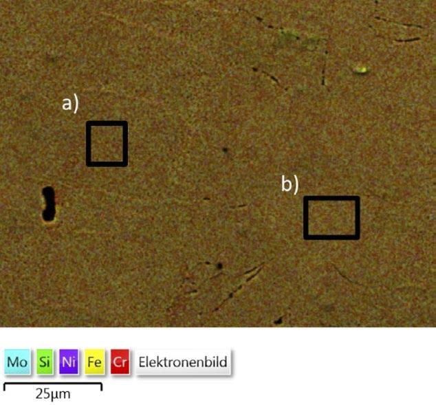
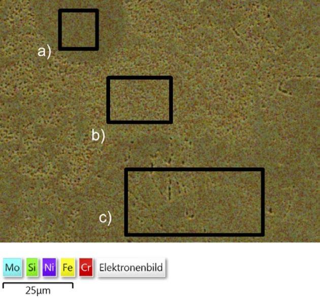
Metal Additive Manufacturing | Winter 2022 110 © 2022 Inovar Communications Ltd Vol. 8 No. 4 | contents | news | events | advertisers | print sub | e-newsletter |
wet
Fig. 4 D1 EDX measured areas Fig. 5 D2 EDX measured areas Name C Cr Mo Ni N Si Mn D1 – calculated 0.02 26.03 4.48 6.75 0.54 0.45 0.90 D1 – analysed 0.02 27.02 4.82 6.23 0.24 0.59 1.14 25 µm 25 µm a) a) b) c) b) Table 6 D1 – Measured chemical compositions by EDX Table 7 D2 – Measured chemical compositions by EDX Element (a) % (b) % (c) % powder % (analysed) Si 0.64 0.62 0.63 0.59 Cr 27.67 27.74 26.80 27.02 Fe Bal Bal Bal Bal Ni 6.55 6.62 6.83 6.23 Mo 4.44 4.73 4.68 4.82 Element (a) % (b) % powder % (calculated) Si 0.66 0.67 0.47 Cr 28.64 28.18 26.20 Fe Bal Bal Bal Ni 5.71 6.09 6.20 Mo 2.65 2.49 2.66 A powder toolkit for PBF-LB
Table 5 Results of
chemical analysis in wt.%
D1 - X
YMod [kN/mm 2] Rp 0.2 [N/mm 2] Rm [N/mm 2] Agt [%] n = 3
x 199.40 608.16 858.26 18.66 s 13.72 8.32 3.30 0.43
Target (1.4501) 200 ≥ 530 730 - 930 ≥ 25
D1 - Z YMod [kN/mm 2] Rp 0.2 [N/mm 2] Rm [N/mm 2] Agt [%] n = 3 x 181.93 602.59 815.83 16.55 s 25.97 1.60 3.55 1.60
Table 8 Results of tensile tests of D1 in X and Z direction
Target (1.4501) 200 ≥ 530 730 - 930 ≥ 25 D2 - X YMod [kN/mm 2] Rp 0.2 [N/mm 2] Rm [N/mm 2] Agt [%] n = 3
x 168.82 583.11 819.86 18.54 s 13.27 3.40 3.46 1.88
Target (1.4501) 200 ≥ 530 730 - 930 ≥ 25 D2 - Z YMod [kN/mm 2] Rp 0.2 [N/mm 2] Rm [N/mm 2] Agt [%] n = 3 x 198.03 559.87 770.65 16.77 s 2.83 1.81 13.99 4.41 Target (1.4501) 200 ≥ 530 730 - 930 ≥ 25
Table 9 Results of tensile tests of D2 in X and Z direction
in the matrix of the specimen after heat treatment [13]. Without diffusion annealing after the build process, the specimens exhibit higher current densities between 0-0.25 V than all other parts. The critical pitting potential is reached first in the fabricated and solution annealed specimen. The others show the critical potential at about 1.25 V.
Fig. 9 shows the corrosion behaviour of D2 compared to PBF-LB 1.4462. Here, the corrosion behaviour is very similar, and the added elements have only a minor positive influence on the corrosion resistance.
Tensile tests
Table 8 presents the average results (x), including the standard deviation (s), of the D1 mix in the X and Z directions compared to the target values of conventionally produced 1.4501. The values for the tensile strength Rm and Rp 0.2 of D1 are within the tolerances of 1.4501. Only the elongation is lower than expected for this material. Early failure in this case may be due to material defects, but also to the presence of intermetallic phases with high Cr and Mo content [14].
The modulus of elasticity was determined from the stress-strain curve and may be inaccurate. The modulus of elasticity of the Z specimen does not reach 200 kN/mm on average, and the standard deviation is twice that of the X specimen. Since all values of the Z specimen are lower, this is probably due to the anisotropic material behaviour of PBF-LB components. This behaviour is generally caused by the rapid melting and solidification process [15]. In general, the stress in the direction of the layers must be lower than orthogonal to the layers.
A similar behaviour can be observed in the results for D2. Table 9 shows the average results (x), including the standard deviation (s), of the D2 mix in the X and Z directions compared to the target values of conventionally produced 1.4501. The modulus of elasticity is low for the X specimen, but the other values are within tolerances and in a similar range to the other specimens.
Metal Additive Manufacturing | Winter 2022 112 © 2022 Inovar Communications Ltd Vol. 8 No. 4 | contents | news | events | advertisers | print sub | e-newsletter |
A powder toolkit for PBF-LB
“The values for the tensile strength
Rm and Rp 0.2 of D1 are within the tolerances of 1.4501. Only the elongation is lower than expected for this material. Early failure in this case may be due to material defects, but also to the presence of intermetallic phases with high Cr and Mo content...”
This
Conclusions
In this research, two different metal powder blends were processed by PBF-LB and compared with samples of pre-alloyed powder and conventionally produced parts. The investigation focused on the homogeneity of the parts and the corrosion resistance and tensile strength that depend on it. The following conclusions can be drawn from the work:
• The parts produced with the powder mixtures were successfully manufactured with PBF-LB, and the chemical composition corresponds to the analysed or calculated powder composition
• Some non-fused particles may occur locally
• Diffusion annealing can reduce the inhomogeneity and improve the corrosion resistance.
• The PBF-LB process itself has a great influence on the corrosion behaviour, especially on the porosity
• The tensile tests show that the parts can be loaded in the same way as conventionally manufactured parts, since the tensile strength is within the tolerances of the material. Only the elongation is somewhat lower
be
to determine a parameter set for stable chemical and microstructural homogeneity at each location of the samples. A reliable process with homogeneous parts is required to bring these alloys into industrial applications.”
Further research needs to be conducted to determine a parameter set for stable chemical and microstructural homogeneity at each location of the samples. A reliable process with homogeneous parts is required to bring these alloys into industrial applications. Further investigation should include a systematic analysis of the heat treatment conditions and the resulting mechanical properties. Heat treatment can potentially lead to a more reliable microstructure. The expected timeline for the powder kit’s development is shown in Fig. 10.
Contact
Michael Norda Project Leader Additive Manufacturing
Fraunhofer IFAM
Wiener Straße 12 28359 Bremen, Germany
michael.norda@ifam.fraunhofer.de www.ifam.fraunhofer.de www.iwm.rwth-aachen.de
References
[1] 'The corrosion of superduplex stainless steel in different types of seawater,' Francis, Ruthie & Byrne,
Metal Additive Manufacturing | Winter 2022 113 Vol. 8 No. 4 © 2022 Inovar Communications Ltd | contents | news | events | advertisers | print sub | e-newsletter | GETPDF
Fig. 10 The expected timeline for the powder kit’s development (Courtesy Fraunhofer IFAM)
2019 2022 2023 2025 2025 Feasibility
Influencing
Corrosion
Heat
structure
in-situ alloying proven
variables understood
resistance improved
treatment creates duplex
PBF-LB powder kit for targeted adjustment of component properties
material properties Powder, PBF-LB parameters, HIP, quality Transfer of the method to other alloys and elements Targeted optimisation of homogeneity and flexibility Next Project Setting the desired properties Automated calculation, creation and preparation of powder blends Production of individualised geometries and materials Future Industrial application of the PBF
powder building kit
Work Improvement and control of the
-LB
A powder toolkit for PBF-LB
“Further research needs to
conducted
Glenn & Warburton, Geoffrey. s.l.: NACE - International Corrosion Conference Series, 2011
[2] Mohammad Hossein Mosallanejad, Behzad Niroumand, Alberta Aversa, Abdollah Saboori. 'In-situ alloying in laser-based additive manufacturing processes: A critical review,' in Journal of Alloys and Compounds 2021, Bd. Volume 872
[3] Clayton, R M, 'The use of elemental powder mixes in laserbased additive manufacturing,' Missouri: Missouri University of Science and Technology, 2013
[4] C Haase, F Tang, M Wilms, A Weisheit and B Hallstedt, 'Combining thermodynamic modeling and 3D printing of elemental powder blends for high-throughput investigation of high-entropy alloys - Towards rapid alloy screening and design,' in Materials Science & Engineering . 2017, S. Bd. 688, pp. 180-189
[5] W Li, X Chen, L Yan, J Zhang, X Zhang and F Liou, 'Additive manufacturing of a new Fe-Cr-Ni alloy with gradually changing compositions with elemental powder mixes and thermodynamic calculation,' in Journal of Advanced Manufacturing Technologies . 2018, S. Bd. 95, pp. 1013-1023
[6] 'Influence of Powder Properties on the Mixing Behaviour of Metal Powders in LPBF,' Michael Norda, Marie Luise Köhler. Digital Conference: s.n., 2021. EuroPM
[7] Shenoy, P, 'Dry mixing of spice powders investigation of effect of powder properties on mixture quality of binary powder mixtures,' s.l.: University College Cork, 2014
[8] Thermocalc Website. [Online] [Accessed: 25.04.2022] https://thermocalc.com/
[9] Satir, Anne and Feichtinger, Heinrich, 'On the solubility of Nitrogen in liquid iron and steel alloys using elevated pressure,' in Zeitschrift fuer Metallkunde 52. 09 1991, S. 689
[10] THC Childs, C Hauser, and M Badrossamay, 'Selective laser sintering (melting) of stainless and tool steel powders: experiments and modelling,' Proceedings of the Institution of Mechanical Engineers, Part B: Journal of Engineering Manufacture . 2005, S. 219(4):339-357
[11] 'Corrosion behavior of 316L austenitic steel processed by selective laser melting, hot-isostatic pressing, and casting,' K Geenen, A Rottger, W Theisen. 2017, Mater. Corros . 68, S. 764-775
[12] Amol B Kale, Byung-Kyu Kim, Dong-Ik Kim, E G Castle, M Reece, Shi-Hoon Choi, 'An investigation of the corrosion behavior of 316L stainless steel fabricated by SLM and SPS techniques,' in Materials Characterization. 2020, Bd. Volume 163
[13] Houbaert, T, Ros-Yañez and Y, 'High-silicon steel produced by hot dipping and diffusion annealing,' in Journal of Applied Physics 91. 13. May 2002
[14] Saeidi K, Alvi S, Lofaj F, Petkov VI, Akhtar F, 'Advanced Mechanical Strength in Post Heat Treated SLM 2507 at Room and High Temperature Promoted by Hard/Ductile Sigma Precipitates,' in Metals 2019;9:199.
[15] Decheng Kong, Xiaoqing Ni, Chaofang Dong, Liang Zhang, Cheng Man, Xuequn Cheng, and Xiaogang Li, 'Anisotropy in the microstructure and mechanical property for the bulk and porous 316L stainless steel fabricated via selective laser melting,' in Materials Letters Volume 235. January 2019, S. 1-5.
Acknowledgements
The work presented was funded by IGF project 20933N of the ‘Forschungsgesellschaft Stahlverformung e.V.’ via the AiF as part of the IGF program by the Bundesministerium für Wirtschaft und Energie.
About the project
The two-and-a-half-year project ‘LPBF Powder Construction Kit’ (IGF 20933 N) started on 01.11.2019 and was completed on 30.04.2022. Work is already underway to continue the development. Interested companies are cordially invited to participate in the projectaccompanying committee of the subsequent research project ’Targeted optimisation of homogeneity and flexibility in the LPBF powder building kit,’ to help shape the investigations in this research project and to find out about the current results. Funding for the project is to be applied for within the framework of the programme for the promotion of joint industrial research (IGF) via the Research Association for Steel Forming (FSV).
Metal Additive Manufacturing | Winter 2022 114 © 2022 Inovar Communications Ltd Vol. 8 No. 4 | contents | news | events | advertisers | print sub | e-newsletter |
A powder toolkit for PBF-LB
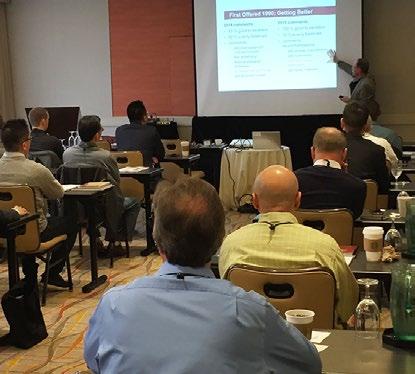
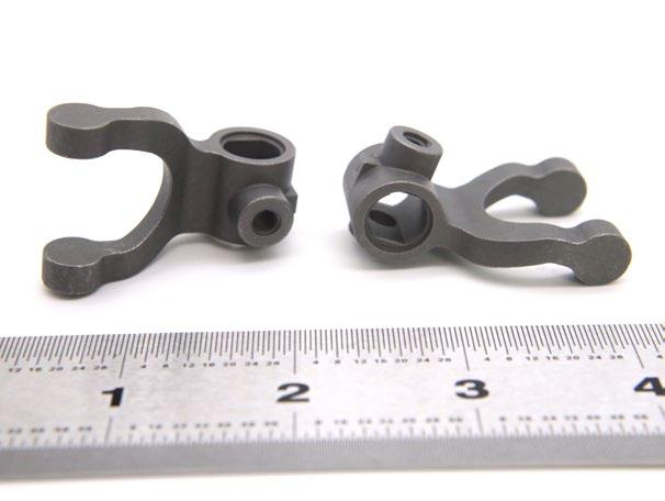
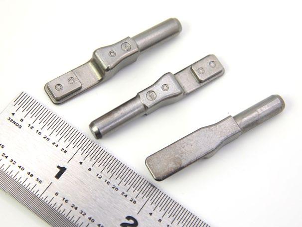
REGISTER BY JANUARY 13, 2023 AND SAVE! For more information, visit MIM2023.org Attend the Only International Powder and Metal Injection Molding Event of the Year! CONFERENCE CO-CHAIRS: Zachary Padasak APG Metal Injection Molding Bryan Sherman DSH Technologies, LLC BONUS: Powder Injection Molding Tutorial Monday, February 27 Conducted by: Matthew Bulger, Former MIMA President Sponsored by: Metal Injection Molding Association 2 0 2 3 International Conference on Injection Molding of Metals, Ceramics and Carbides Febr uar y 27–March 1, 2023 • Hilton Orange County/Costa Mesa, CA MIM2023 is a Hybrid Conference—Attend In-person or Vir tually
The World Congress on Powder Metallurgy was held in Asia in 2006 in Busan, South Korea, in 2000 in Kyoto, Japan, and in 2012 in Yokohama, Japan. It is an excellent opportunity to exchange the latest information and deepen friendships in Yokohama Japan. Advanced technologies and information for "Carbon Neutral", "Electrification" and "Energy Saving"


Organized by
Supported by Japan Powder Metallurgy Association (JPMA) Japan Society of Powder and Powder Metallurgy (JSPM)
European Powder Metallurgy Association (EPMA) Metal Powder Industries Federation (MPIF) Asian Powder Metallurgy Association (APMA)
WORLD
in YOKOHAMA Japan “Make a
with PM”
PM2024
better world
WORLD PM2024 Congress & Exhibition International Powder Metallurgy 13-17 October 2024 YOKOHAMA, JAPAN
www.worldpm2024.com
QuesTek's ICMD: Faster, cheaper, and better alloy development for Additive Manufacturing
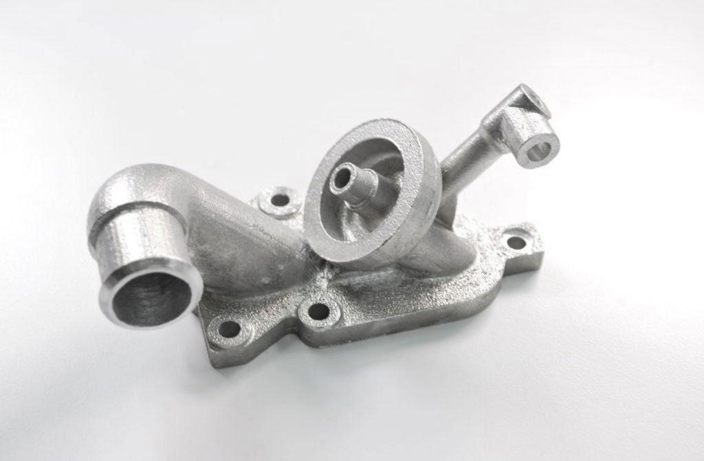
Alloy development has evolved dramatically throughout history, from what was a game of 'trial and error' to a systematic approach driven by Design of Experiments and specialist software. Now, the adoption of Integrated Computational Materials Engineering (ICME) is once again changing the way new materials are developed and deployed in today's advanced manufacturing technologies. QuesTek's Keith Fritz, Director of Solutions Architecture, details how the company's ICMD® platform is enabling faster, cheaper and more successful development of new alloys for metal Additive Manufacturing, as well as the build parameters to process them.
The way materials engineers develop novel alloys has changed radically over time. In early foundry work, alloy development was a game of trial and error. At the direction of the person most familiar with the practice, materials engineers would make minor changes to the material composition and/or process, then capture and measure the results downstream. The results of these trials could be a little fuzzy; it was not always clear how impactful the ‘change’ was, and what was really driving the results.
The next substantial development was the widespread adoption of lean six sigma, in particular the Design of Experiment (DoE) approach combined with the statistical software Minitab®. This democratised experiments and gave engineers access to tools that enabled them to approach alloy development systematically. Six sigma provided a structure for experiments and a clear ‘line in the sand’ – decided by statistics – that determined the most impactful factors.
A major shift in manufacturing was the introduction of AM. The reality of building three-dimensional metal objects which could never have been manufactured by conventional means was a radical departure from subtractive-minded designs and tooling-heavy processes.
This brings us to today, where the adoption of Integrated Computational Materials Engineering (ICME) promises to change the way new materials are developed and deployed. Through the creation of its unique ICMD® software platform, QuesTek hopes
Fig. 1 A demonstration part built with a Questek developed high-temperature aluminium alloy for PBF-LB
Metal Additive Manufacturing | Winter 2022 117 Vol. 8 No. 4 © 2022 Inovar Communications Ltd | contents | news | events | advertisers | print sub | e-newsletter | GETPDF QuesTek: AM alloy development
Keyholing
Lack of fusion - depth
Lack of fusion - hatch Balling

Fig. 2 Printability map of material suitability for AM produced using ICMD. Map shows defect formation as a function of laser parameters
to enable each and every materials engineer to accelerate the development and adoption of new alloys for AM.
QuesTek aims to empower innovators by resolving material challenges. The company is currently a market leader in Integrated Computational Materials Engineering; our Materials by Design® technologies have been proven to reduce the development time and cost, and increase the performance, of novel materials. We are the only company in its market space that can take an innovative design through production, certification, and flight qualification using its own materials, in a fraction of the time and cost of traditional, or purely algorithmic, methods.
What is ICMD?
Integrated Computational Materials Design combines fundamental computational physics and informatics with systematic experimentation and advanced manufacturing. It integrates a top-down methodology, using informatics tools to mine materials databases, product characteristics, and manufacturing process performance with bottomup multiscale modelling based on fundamental physics. ICMD places a major emphasis on the processstructure-properties-performance (PSPP) relationship to gain an understanding of how processes produce material structures, how those structures give rise to material properties, and how those properties produce specific performance, to enable the
better selection and development of materials for a given application. Both process-structure and structureproperty models are examined and modified in ICMD to optimise results.

It is the ‘I’ (Integrated) in ICMD that counts; the integration of multiple materials modelling tools linked together is what supports a full understanding of selection, development, and performance in an Additive Manufacturing application.
In this model of a material, the four components are linked with physicsbased models of the interactions. The model starts with the process. In the case of Additive Manufacturing, the process includes the elemental composition of the alloy, the powder characteristics, thermal histories, and various laser parameters. By inputting this process, the microstructure of the material can be predicted using first principle, fundamental physics. Such structures include matrix phase properties, grain structure, solidification characteristics, defects that may be generated, and more. Once the structure of a material has been predicted, another set of physicsbased models is used to predict the properties associated with that structure. Typical material properties include density, mechanical properties, electrical conductivity, and susceptibility to hot cracking, to name a few. Once the properties of the material are determined, yet another set of physics-based relationships can be applied to the material's performance. This enables the user to target a broad spectrum of performance attributes, from toughness, thermal properties, fatigue, corrosion, and creep, to sustainability.
How ICMD is applied to AM process parameter sets
In Additive Manufacturing processes, to model melt pool dynamics, QuesTek creates a testing matrix of various laser speeds, power, and hatch distances. Once the samples are made (specific to the machine and alloy), we measure the melt pool characteristics, including width and penetration
Metal Additive Manufacturing | Winter 2022 118 © 2022 Inovar Communications Ltd Vol. 8 No. 4 | contents | news | events | advertisers | print sub | e-newsletter |
“[ICMD]...integrates a top-down methodology, using informatics tools to mine materials databases, product characteristics, and manufacturing process performance with bottom-up multiscale modelling based on fundamental physics.”
250 300 350 400 450
50 100 150 200
0.5 1 1.5 2 2.5 3 Speed (m/s)
Power (W)
QuesTek: AM alloy development
depths. With that, we can predict the optimal machine parameters. We can model weld balling, keyholing, and lack of fusion defects for both hatch and depth. Using those processcalibrated models, we generate a processing map to identify the optimal parameter set in the tradeoff between throughput and part quality. Fig. 2 shows an example of an ICMDproduced additive manufacturability map. The area in grey would be considered the optimal processing range.
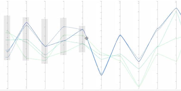
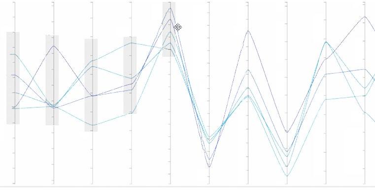
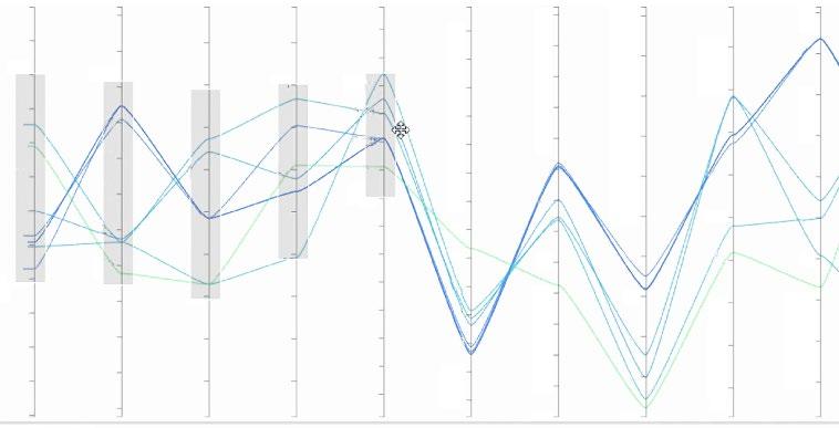
Understanding how this map is created provides processing guidance in both directions. Once a process is established, one can look at a raw material input change (let’s say a new material lot with different chemistry) and determine how that new material chemistry might respond at the established parameters, without even a sample build. Fig. 3 shows how changes in elemental composition would impact material properties This is a great tool for overall quality control and incoming raw material disposition.
Development of a parameter set with a traditional DoE approach could take well over a year to complete, focusing only on density and keyhole defects. This ICMD approach takes only several weeks to a few months, and creates data and models that can later be used to produce answers to more complex questions such as fatigue life, making it uniquely suited to address industry challenges in a fraction of the time.
Expedited development of AM parameters for new alloys
One of the most important opportunities to take advantage of ICMD is the development of robust AM regimes for new alloys. It becomes exceptionally easy to query material compositions as they relate to process prediction and subsequent material structure. Fig. 3 shows an example of an interactive chart of elemental composition and proper -
a) b) c)
60 60 60
58 58 58
56 56 56
54 54 54
52 52 52
50 50 50
48 48 48
Ni
Cr W Co C Hot cracking index
Yield strength [MPa] Corrosion resistance Carbides as built TCP as built
25 25 25
24 24 24
23 23 23
22 22 22
21 21 21
20 20 20
17 17 17
16 16 16
15 15 15
14 14 14
13 13 13
13 13 13
12 12 12
11 11 11
10 10 10
9 9 9
0.10 0.09 0.08
0.14 0.10
0.12 0.12 0.08
0.11 0.11 0.07
0.13 0.09
3.0 3.0 3.0
2.8 2.8 2.8
2.6 2.6 2.6
2.4 2.4 2.4
2.2 2.2 2.2
2.0 2.0 2.0
1.8 1.8 1.8
1.6 1.6 1.6
1.4 1.4 1.4
1.2 1.2 1.2
1.0 1.0 1.0
0.8 0.8 0.8
0.6 0.6 0.6
0.4 0.4 0.4
Ni Cr W Co C Hot cracking index
2.6 2.6 2.6
2.4 2.4 2.4
2.2 2.2 2.2
2.0 2.0 2.0
1.8 1.8 1.8
1.6 1.6 1.6
1.4 1.4 1.4
1.2 1.2 1.2
1.0 1.0 1.0
0.8 0.8 0.8
0.6 0.6 0.6
0.4 0.4 0.4
0.2 0.2 0.2
0.0 0.0 0.0
5.0 5.0 5.0
4.5 4.5 4.5
4.0 4.0 4.0
3.5 3.5 3.5
3.0 3.0 3.0
2.5 2.5 2.5
2.0 2.0 2.0
1.5 1.5 1.5
1.0 1.0 1.0
0.5 0.5 0.5
0.0 0.0 0.0
500 500 500
495 495 495
490 490 490
485 485 485
480 480 480
475 475 475
470 470 470
465 465 465
460 460 460
62 62 62
60 60 60
58 58 58
56 56 56
54 54 54
52 52 52
50 50 50
48 48 48
46 46 46
Ni Cr W Co C Hot cracking index Yield strength [MPa] Corrosion resistance Carbides as built TCP as built
Yield strength [MPa] Corrosion resistance Carbides as built TCP as built
44 44 44
Fig. 3 Interactive chart to query how various elemental compositions change material properties
Metal Additive Manufacturing | Winter 2022 119 Vol. 8 No. 4 © 2022 Inovar Communications Ltd | contents | news | events | advertisers | print sub | e-newsletter | GETPDF
QuesTek: AM alloy development
β transus (K)
Expected yield strength (MPa) Density with rule of mixture (g/cm3) 40 30 20 10 0 2 4 6 8 10


550 50
models their predictive power and trusted outputs. After the process is modelled, calibrated, and validated, you have created a digital twin of the process. This digital twin of the additive process has unique benefits that give businesses an edge in the market.
In one scenario, modelling allows us to predict the best yield strength as a function of alloy composition and processing conditions. This helps us understand which energy densities might be optimised within a given set of AM bounds. Fig. 4 shows the light blue lines superimposed on the Solidus mass fraction plot. These are expected yield strength curves as a function of solidus temperature versus aluminium mass fraction in titanium base metal.
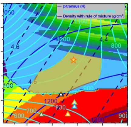
Ti-6Al-5Fe [5] Ti-6Al-1.7Fe [9] Ti-5Al-1Fe [9] Ti-3.5Al-1Fe [9]
62s (Ti-6Al-2Fe)
Fig. 4 Predicted yield strength as a function of solidus temperature and aluminium/titanium mass fraction
ties that a designer can manipulate to query various compositions and how changes affect properties.
Using ICMD, a designer can quickly vary the composition of any of the alloying elements and see how those changes affect critical build parameters as well as desired properties.
As a demonstration, Fig. 3 shows only a portion of the alloy and a portion of the properties; the chart is far more comprehensive in practice.
QuesTek's background in Additive Manufacturing
QuesTek has a long history in Additive Manufacturing, having completed over seventy different engagements. Clients have included the US Defense Advanced Research Projects Agency (DARPA); the US Army, Navy, and Air Force, and numerous corporate entities. Materials addressed by the engagements include nickel superalloys, aluminium, titanium, stainless steels, niobium, tungsten, magnesium, high-entropy alloys, Invar, metallic glasses, and other
complex alloy systems. QuesTek deliverables in AM have been consistently recognised by leading materials forums.


For example, in 2020, QuesTek received first place in the America Makes-Air Force Research Lab AM Modeling Challenge Series, by delivering improved understanding of the structures and performance of additively manufactured metallic components made from IN625 superalloy. In 2022, QuesTek won first place for Best Modeling Results Predicting Macroscale Tensile Behavior of IN625 from The AM Best Awards, a joint programme of the National Science Foundation (NSF) and the Minerals, Metals, and Material Society (TMS).
Digital twin and modelling
QuesTek’s models are not only created in cyberspace. Models are calibrated and validated using samples produced by the same operation that is being modelled. This practice is what gives our
QuesTek’s ICMD approach has other strong advantages beyond faster development time. For part qualification, ICMD can reduce the number of tests needed. Instead of having to produce and test samples over the entire design space –which can be extremely lengthy and costly – ICMD can drastically lower the number of tests required by targeting only high informational value samples. Recently, QuesTek formulated an approach to accelerate qualification for fatigue critical materials, wherein digital twins of fatigue samples are generated to simulate fatigue tests, reducing the testing needed to establish a material dataset for one client by 60%.
This approach provides three key benefits in the qualification of additively manufactured materials: (1) reduced cost, (2) reduced time, (3) increased mechanistic understanding of the key features driving fatigue. Though ICMD is not a surrogate for required testing for AMS or MMPDS qualification, it plays a significant role in carefully expediting part of the design, development, and qualification process. Being at the centre of digital transformation alongside machine learning, we may think of the day when ICMD (and other computational tools) will be used in place of the required tests for these standards organisations, but do not get
Metal Additive Manufacturing | Winter 2022 120 © 2022 Inovar Communications Ltd Vol. 8 No. 4 | contents | news | events | advertisers | print sub | e-newsletter |
250
500 450 400 350 300
200 150 100 50 0
Ti-5Al-2.5Fe [7] TIMETAL
[8] 10 8 6 4 2 Fe (%, mass fraction) Al (%, mass fraction)
Tstart - 700K Tstart - Tsolidus
QuesTek: AM alloy development
too nervous – this is a long way from where we are today.
That is not to say that ICMD is not valuable in MMPDS qualification. On the contrary, it can be critical in many instances. Here is a quick story for you: Prior to engaging with us on ICMD, a (now) client of ours had intended to use a custom heat treatment cycle for their additive alloy, but when they went to their OEM partners, the cost of this custom cycle was prohibitive, it was more expensive than the standard cycles the partners had budgeted for. The company moved ahead, making qualification samples with a less expensive standard heat treatment cycle. The mechanical testing for these samples did not perform as expected, with the standard deviation showing 2–3 X higher than anticipated.
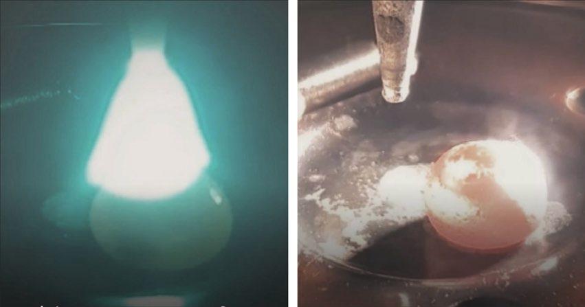
When engaged to perform a postmortem investigation, it was revealed that the heat treatment was too close to the formation of a deleterious phase. QuesTek’s ICMD digital twin of the process would have seen this issue before considerable resources were used in producing and testing samples. If the standard heat treatment was a fixed constraint, it may have been possible to make some adjustments to the alloy chemistry or build parameters to avoid this deleterious phase region. In this way, ICMD can act as an insurance policy or final check before hundreds of thousands of dollars and months of time are spent testing samples. Once the ICMD models are made and calibrated, you can be sure of the results of physical testing within narrow statistical bounds.
Process optimisation
Once these models, or digital twins, of the process are produced and calibrated, they are not specific to one area. Models are not generated separately for the process parameters, fatigue, or heat treatment simulation, but are linked together to represent the entire process. This digital twin approach allows you to optimise the process and investigate how different
variables may impact the process without having to change machine settings or produce custom alloy formulations.
In most operations, there is a nagging question about the pickup of trace elements from the reuse of powder or remelting of scrap parts back into master heats. Having the ICMD digital twin, we can simulate what an increase of 10–100 ppm of nitrogen would impact to the microstructure and, thus, the final performance of the parts. This can help put to rest sometimes decadelong arguments, and it also may show the process has some robustness that would allow for increased scrap use or more reuse cycles for a lot of powder.
Materials concurrency
The concept of material concurrency states that the material can be engineered in parallel with the
-
product it is to be used for, and, thus, the material can be optimised for its application. Often, in the AM space, the materials being used are not given proper consideration. In the early days of AM, common and well-known alloys would be turned into powder for AM. It was a hard lesson to learn that many of these alloys were not optimal for Additive Manufacturing. It was not until later that alloys custom tuned to the challenges of AM would come along, and QuesTek’s patented alloys have been optimised to produce desirable properties unique to the AM process. Materials concurrency is the design of the material to mate with the process to create an optimised product. Novel materials enable novel products.
QuesTek’s Materials Concurrency approach can do for Additive Manufacturing what it did for the Apple Watch. With our involvement and an investment in 2012, Apple applied QuesTek technology to develop
Metal Additive Manufacturing | Winter 2022 121 Vol. 8 No. 4 © 2022 Inovar Communications Ltd | contents | news | events | advertisers | print sub | e-newsletter | GETPDF
QuesTek: AM alloy development
“It was not until later that alloys custom tuned to the challenges of AM would come along, and QuesTek’s patented alloys have been optimised to produce desirable properties unique to the AM process.”
Fig. 5 Arc melting of a button sample at QuesTek's materials lab to charac
terise and test novel alloy designs
critical materials for the Apple Watch. The watch hit the market in April 2015; throughout that year, 15 million units were sold, and 50+ million units were sold each year between 2016 and 2019, generating an incremental $1.5 billion in revenue each year. The ‘right’ alloy was critical to launching the watch and, at the end, investment in QuesTek’s Materials Concurrency led to a speedy developmental cycle and billions of dollars in fast-growing revenues.
Accelerated insertion of materials
The incorporation of new materials into engineered products – particularly in mission-critical industries such as aerospace, medical device, automotive or energy – can entail numerous steps and production runs to qualify the material and develop statistically driven properties used by design engineers. Failure to achieve material properties accurately and repeatedly at full-scale production levels can be costly and timeconsuming. QuesTek uses Materials by Design® technology and our expert skills in Accelerated Insertion of Materials (AIM) to cut down on these risks and costs.
QuesTek was a key contributor to the AIM programme, a strategic initiative led by DARPA and the Naval Research Laboratory (ONR). The AIM programme produced a new way to develop materials that makes it easier to use new materials in the same amount of time as part of the development and design cycles. The AIM programme has achieved the following results:
• Made it possible to set material requirements that are design driven by tightly linking design and material activities and tools
• Provided designers with early material properties, with confidence bounds, throughout the development cycle
• Allowed users to control material performance, producibility, and cost
• Lowered the risk of using a new material while also reducing the cost and time needed to produce data
An exemplary client success story of Accelerated Insertion of Materials is the US Navy carrier aircraft landing gear hook shanks. Under a contract with the Navy, QuesTek designed, produced, qualified, and placed the certified products, made of QuesTek’s proprietary Ferrium® M54 alloy, into flight operations on the Navy’s T-45 trainer aircraft, in a third of the time of a typical designto-flight cycle (in approx. seven years vs twenty years). The hardness and toughness of the new gear enabled more than two times more landings on the platform, saving millions in maintenance costs and preventing numerous accidents, loss of aircraft (a T-45 costs $17.2M each), and injury or loss of young aviators.
Proprietary materials
QuesTek has thirteen US Patents for ICMD advanced alloys and five US Patents for ICMD advanced alloys used in Additive Manufacturing. It also currently has fourteen US patents pending for additional novel materials. We mostly license our proprietary materials to leading material manufacturers, but we have also shown that we can build and manage custom supply chains for specific, high-performance applications of our proprietary materials for both corporate and government end-use clients. QuesTek’s AM-specific alloys include:
• An AM aluminium alloy that maintains high strength at temperatures over 250ºC for extended life (e.g., 1000 hours at temperature)
• An AM aluminium alloy that has room temperature strength on the order of 7000 series aluminium alloys (without ceramic particle dispersion which can reduce fatigue strength)
• A true 'build and go' 17-4 PH AM stainless steel alloy, which
under proper build parameters, meets wrought 17-4 PH properties without requiring post-processing solution treatment or age
• A higher-strength Nickel 718 alloy
• Nickel aluminium bronze
• A carburisable Ferrium C64 for gears and other high-toughness, high-wear applications
• HEAs (high entropy alloys)
• Gradient Niobium AM alloy compositions
• Equiaxed, isotropic titanium alloys
Conclusion
Thanks to remarkable breakthroughs and major advances over the previous decade, QuesTek’s Integrated Computational Materials Design provides a unique designing and manufacturing paradigm for accelerating the research and development of innovative materials. When combined with advances and improvements in Additive Manufacturing, ICMD has been proven to create a design and manufacturing paradigm shift in which digital twins make it possible to design materials faster, cheaper, and better suited to their application.
Contact Keith Fritz, Director of Solutions Architecture kfritz@questek.com
Severine Valdant, Chief Sales & Marketing Officer svaldant@questek.com
QuesTek
1820 Ridge Avenue, Evanston, IL 60201, USA www.questek.com
Metal Additive Manufacturing | Winter 2022 122 © 2022 Inovar Communications Ltd Vol. 8 No. 4 | contents | news | events | advertisers | print sub | e-newsletter |
QuesTek: AM alloy development


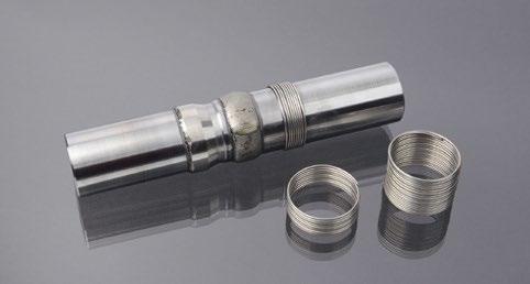
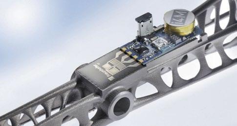

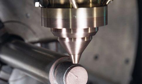
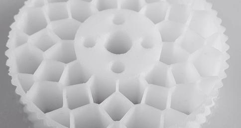
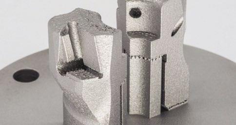
For more information visit the DDMC website:
Additive Manufacturing The Fraunhofer Direct Digital Manufacturing Conference (DDMC) is a cuttingedge forum for discussion on Additive Manufacturing in Berlin, Germany, and brings together researchers, educators and practitioners from around the world. Highlights of our biennial conference are: More than 50 paper and poster presentations, including Best Paper and Best Poster award Latest trends from industry Evening networking event in a historic location Accompanying exhibition Full conference proceedings and special issue of Springer journal „Progress in Additive Manufacturing“ (PIAM) Aditya Chandavarkar, CNT Expositions and Services LLP, India Dr. Barbara Imhof, LIQUIFER Systems Group, Austria Prof. Mihaela Vlasea, University of Waterloo, Canada Dr. Özlem Weiss, Expertants GmbH, Germany Our high profile keynote speakers are www.ddmc.fraunhofer.de FRAUNHOFER DIRECT DIGITAL MANUFACTURING CONFERENCE 2023 FRAUNHOFER COMPETENCE FIELD ADDITIVE MANUFACTURING DDMC 2023 | BERLIN | MARCH 15-16, 2023
© Images by Fraunhofer Competence Field
NanoAL: Alloy development on an open parameter PBF-LB machine, from installation through to Rapid Alloy Screening
When NanoAL, LLC, a company with a decade of aluminium alloy development experience, decided to speed up its development of alloys for AM, it turned to SLM Solutions' SLM®125 PBF-LB machine. As NanoAL's Matthew Simmers explains, the company needed a workhorse machine that fulfilled a number of requirements, from open parameters and material flexibility to specifications and build quality that closely mirrored larger, production-focused machines. This article explores machine choice, installation, and operation in supporting NanoAL's Rapid Alloy Screening (RAS) process.
NanoAL was founded in 2013 as a spin-out from the materials research department of Northwestern University, Illinois, USA, with the goal of expanding upon and commercialising seventeen years of research in advanced aluminium alloys. This entry into the start-up world of material development has led NanoAL to work with global corporations to develop advanced aluminium alloys for applications in energy, semiconductors, automotive, beverage packaging, and general industry.
Along the way, the concept of Addalloy® aluminium powders emerged, as the NanoAL alloy design methodology was first turned towards Additive Manufacturing. NanoAL’s AM powders are specially formulated to take advantage of the fundamental physics of the powder production and Laser Beam Powder Bed Fusion (PBF-LB) processes. In 2020, the company’s first product for AM, Addalloy 5T, was announced, a 5000-series based high-strength alloy that can be one-step stress relieved and peak aged without quenching (Fig. 1). Fast forward to
the fourth quarter of 2022, and the Addalloy concept has expanded to include additional available alloys as well as customised powder development services for public and private partners.
Today, NanoAL continues to solve material problems using a thoughtful, scientific approach that takes into
account the end-user’s economic requirements at the earliest stages of development. NanoAL specialises in aluminium alloy development, but works broadly across traditional and advanced manufacturing processes including sheet rolling, die casting, wire forming, and AM powders. The development team utilises an inter -
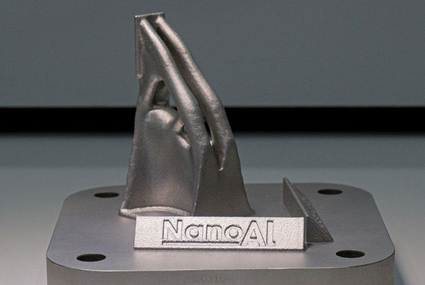
1 A
part
Metal Additive Manufacturing | Winter 2022 125 Vol. 8 No. 4 © 2022 Inovar Communications Ltd | contents | news | events | advertisers | print sub | e-newsletter | GETPDF NanoAL on Rapid Alloy Screening
Fig.
test
produced using NanoAL’s Addalloy 5T powder (Courtesy NanoAL)
nally created metallurgical toolbox called Rapid Alloy Screening (RAS) that rapidly produces empirical data against modelled predictions. In 2021, NanoAL further expanded its capabilities for development in Additive Manufacturing with the addition of an SLM Solutions SLM 125 PBF-LB machine to the RAS toolbox.
NanoAL selected the SLM 125 from amongst stiff competition in the marketplace for its open-parameter platform, optimal build chamber size, and simple material changeover process. Although smaller in effective build volume, it is representative of the larger format PBF-LB machines on the market, with excellent process gas flow, a powerful 400 W laser, and
a production-grade powder distribution system. Very quickly, the SLM 125 proved its merit.
SLM 125: The little big hitter
The SLM 125 metal PBF-LB machine has been a workhorse in the dental field, building customised dental devices such as bridges and crowns for years. As a machine, it is both flexible and capable; perfect for highvalue applications that use expensive raw materials, or for one-off builds of customised devices. Now, universities and material companies are noticing that the SLM 125 is well suited to the
laboratory environment, as it is an excellent bridge between entry-level PBF-LB machines, which are often too small and underpowered, and the more productive, and significantly more expensive mid-format machines in the 220 mm build chamber size.
This is important for the purposes of research and development of new alloys, something that metal Additive Manufacturing certainly needs. The SLM 125 has many of the benefits of a larger SLM Solutions machine, but also much of the flexibility needed for companies and universities that are not running production parts. Size and utilities are often a particular consideration for laboratories, where space is at a premium and a full-scale custom build out is not possible.
Compared to other systems available today, the SLM 125 has a compact build chamber with a hopper-fed powder spreading system, which results in a small machine footprint (1400 x 900 x 2460 mm) relative to the part size that can be produced.
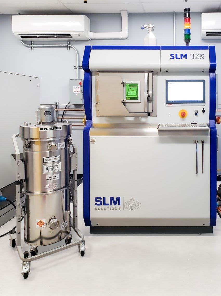
Utility requirements for metal AM machines include power, clean air supply, and inert gas - typically argon or nitrogen (Fig. 3). The circuit amperage for a dedicated lab space consisting of the SLM 125, the laser cooling system, a powder reconditioning sieve, a metal dusts vacuum, lighting, and dedicated HVAC is approximately 100–120 A. Air and inert gas system options can be selected at the user’s preference. NanoAL installed a screw-type air compressor with downstream filtration, drying and separation to achieve the high-class air required for the laser optics. The SLM 125 can be connected to argon and nitrogen at the same time, which is convenient for development since plumbing does not need to be changed over. The user selects the desired gas from the SLM 125’s user interface for each build.
Most installations will elect to provide argon from an array of bottles or a larger dewar purchased from a compressed gas distributor. Nitrogen can be similarly sourced from the same distributor, but it can also be conveniently generated on-site with a compact nitrogen generating tower
Metal Additive Manufacturing | Winter 2022 126 © 2022 Inovar Communications Ltd Vol. 8 No. 4 | contents | news | events | advertisers | print sub | e-newsletter |
NanoAL on Rapid Alloy Screening
Fig. 2 The small-scale SLM 125 metal PBF-LB machine
that is connected to the same air supply system as the laser optic.
While the SLM 125 is the smallest machine in the SLM Solutions portfolio, it offers greater capabilities than other small commercial machines currently in the market and is more representative of the processes utilised in larger-format machines. This allows a single machine to mature a new alloy from the research stage into commercialisation. In terms of the build chamber and mechanics, the SLM 125’s systems are essentially scaled-down versions of those found in its bigger brother, the SLM 280.
The build chamber piston, build plates, inert gas pumping system, condensate filter, powder dispenser and recoater are all mechanically similar to the SLM 280 in design and function, which gives users confidence that developing build parameter sets on the SLM 125 will be translatable to larger platforms where material properties can be replicated and validated. Equipped with a single 400 W laser, the SLM 125 has the same power and scan speeds as the entry-level SLM 280, and the build volume is also preheatable up to 200°C which further
increases its ability to handle alloys that are sensitive to thermal stress.
Setting up the room
Unlike many polymeric AM machines, which can often be safely used in an office or even a home environment, metal PBF-LB machines require special safety considerations.
Metal powders for AM are sized in microns. Some common powder sizes are +15/-45 μ m, +15/-53 μ m, and +20/-63 μ m. These metal powders may have health, safety, and environmental risks associated with them.
To mitigate these risks, metal powder AM machines are often installed
in specialised rooms that are designed and engineered to suit the process and the materials. To ensure the safe and proper operation of the SLM 125 in its laboratory, NanoAL engaged with the local fire department, external safety consultants, and engineering contractors to determine the needs of the electrical service, HVAC, and fire suppression in the space. An existing room was upfit from its original state to provide the necessary utilities and operating environment and to meet the engineering design requirements put in place to mitigate dust migration and upgraded fire protection.
Metal Additive Manufacturing | Winter 2022 127 Vol. 8 No. 4 © 2022 Inovar Communications Ltd | contents | news | events | advertisers | print sub | e-newsletter | GETPDF
“While the SLM 125 is the smallest machine in the SLM Solutions portfolio, it offers greater capabilities than other small commercial machines currently in the market and is more representative of the processes utilised in largerformat machines.”
Air
NanoAL on Rapid Alloy Screening
Fig.
3
Typical
utility setup for a metal Additive
Manufacturing
space Air filtration PSM100 Chiller SLM 125 Nitrogen generator
compressor Electrical transformer Electrical panel Argon Bottles
Dust migration
While metal AM powders tend to disperse into air easily, NanoAL specialises in aluminium powders, which are much lower density than other AM metals such as steel, copper, and titanium. This means that aluminium powders are the most likely to become airborne during handling operations such as loading and unloading the machines – the manual process shown in Fig. 4. Dust migration is a central concern because metal dusts may:
• Be harmful if inhaled or swallowed
• Irritate the eyes, nose, and throats tissues
• Contaminate other areas of the laboratory, causing cleanliness issues
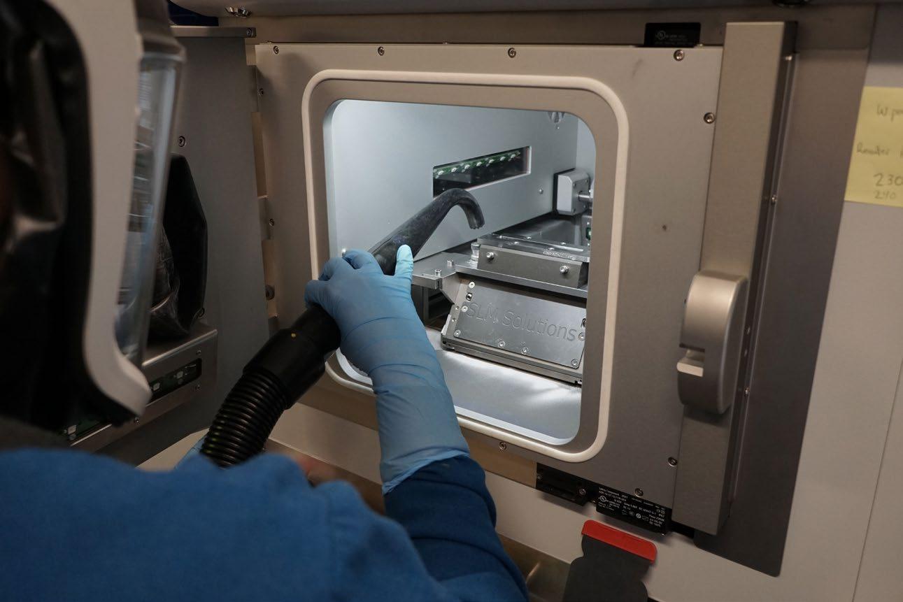
• Be explosive when dispersed into the air
The walls, doors, floors, and ceiling act as the primary barriers of the enclosed room. All penetrations into the room for process gas supply, plumbing lines, power, and data cables were sealed. Engineering controls were incorporated to further ensure metal powder does not escape the room. Dedicated in-room mini-split heating/ cooling units were installed to separate the climate control within the room from the primary HVAC throughout the rest of the lab. Make-up air was ducted into the room and was paired with a dedicated room exhaust system. The supply and exhaust side were balanced to create a slightly negative pressure inside the room. The negative pressure ensures that any unsealed penetrations would not be routes for metal powder to escape. Personal protective equipment (PPE) is worn by operators
to prevent exposure to metal powder during handling. The PPE includes a Powered Air-Purifying Respirator (PAPR) with a full-face shield to cover eyes, nose and mouth, and a fire resistant overgarment with long-cuff nitrile gloves.
Fire protection
Metal powders may have certain fire related hazards. NanoAL contracted a fire and safety engineering firm to confirm the local and national regulations required for working with aluminium powder. A dry-chemical fire suppression system (Figs. 5 and 6) was necessary to meet the potential hazards outlined in NFPA 651
‘Machining and Finishing of Aluminum and the Production and Handling of Aluminum Powders.’ There are two potential hazards when working with aluminium powders that drive this requirement. First: aluminium powders may present a metal fire
Metal Additive Manufacturing | Winter 2022 128 © 2022 Inovar Communications Ltd Vol. 8 No. 4 | contents | news | events | advertisers | print sub | e-newsletter |
NanoAL on Rapid Alloy Screening
Fig. 4 NanoAL operator cleaning the SLM 125 build chamber after a successful build. The build volume measures 125 x 125 x 125 mm, effectively producing a part with a maximum dimension of 10.2 cm
hazard if a fire spreads from an adjacent area of the building to the AM room. An overhead water suppression system is not suitable for a metal fire as it may cause the fire to spread more rapidly. Second: aluminium powders can react with water from an overhead sprinkler system to evolve hydrogen, a flammable gas. The small metal powders used in AM have a very large surface area relative to their volume, which increases the rate of this reaction. The local fire department provided the final review and approval of the engineered dry chemical fire suppression system.
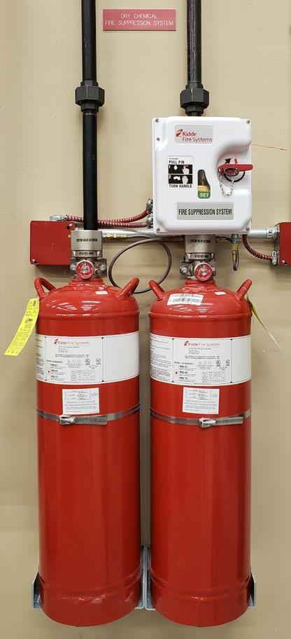
Developing alloys for AM
Alloy development for AM tends to follow a certain path, starting in ideation, moving through initial parameter development with testing and validation, and finally to application development, production scale up, and commercialisation. For NanoAL, the Rapid Alloy Screening process (Fig. 7) is put to work at the very first step: ideation.
Rapid Alloy Screening (RAS)
When starting a new alloy development programme, NanoAL uses machine learning to scan its proprietary metallurgical database for compositions suitable to new application requirements and the physics inherent to the AM process. A design of experiment is created to explore the new design space and then the alloy coupons are produced by NanoAL utilising a specially developed casting process. The coupons are loaded into the SLM 125 in an array to test the whole DOE space with a single experiment, including a fundamental study in the laser power and scan speed relationship for each composition in the test. The results of this experiment are the first brick from which the foundation for a new alloy is laid.
At this point, a hurdle is encountered by all alloy developers: the first trial atomisation. When developing a new alloy, making the commitment to atomise a powder for the
Metal Additive Manufacturing | Winter 2022 129 Vol. 8 No. 4 © 2022 Inovar Communications Ltd | contents | news | events | advertisers | print sub | e-newsletter | GETPDF
Fig. 5 Dry chemical system controller and communication panel
Fig. 6 Dry chemical system actuator and compressed extinguishing agent
Ideation, modelling
machine
Pre‐atomisation design space and empirical data Atomising first batch of new powder
confirmation of properties
batches, quality control, and machine learning data NanoAL on Rapid Alloy Screening
Fig. 7 The circular RAS process feeds data back to ideation to inform next generation alloy development
and
learning
Empirical
Subsequent
first time is an important moment. There are many uncertainties. Will it atomise well? What will the yield be? Is the morphology suitable? And, most importantly, is the composition correct?
Compositions developed by NanoAL during the ideation phase are
well informed, having already been simulated on computer, produced with empirical casting trials, and tested with empirical laser scanning assessments. However, they are not without risk, and each subsequent atomisation requires that NanoAL accommodate for any adjustment in the alloy’s composition, sizing, morphology, or any other critical aspect, adding significant lead time and cost to a programme. NanoAL creates a complete powder specification and partners with established metal powder producers to atomise it at the research scale. An SEM image of trial powders atomised to NanoAL’s specification is shown in Fig. 8.
The amount of powder yielded in the desired particle size range can be unpredictable in a trial run, and the SLM 125 is well suited to accommodate this variability. Its build chamber size and powder feed systems mean as little as 3 kg of aluminium powder can produce basic results defining the suitable build parameter range and basic material properties, including XY
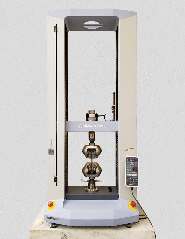
tensile performance (Fig. 9). With larger quantities of powder, the SLM 125 can generate coupons for Z and XYZ oriented mechanical coupons. Coupons from the SLM 125 are machined at NanoAL using a CNC lathe to produce repeatable and reliable test specimens. With every step of the process in-house, development builds can be built, heat treated, machined, and characterised within forty-eight hours.
An alloy composition can be locked in with as few as one or two research-scale atomisations. From here, the SLM 125 continues to contribute to the maturation of the new alloy. Incoming production batches of alloy powder go through the typical quality control checks such as powder size distribution analysis, elemental composition analysis, morphology, density, and flow checks.
NanoAL uses the SLM 125 to perform a build performance check on all incoming Addalloy powder batches to confirm that new batches of powder additively manufacture in
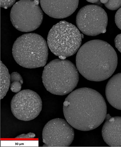
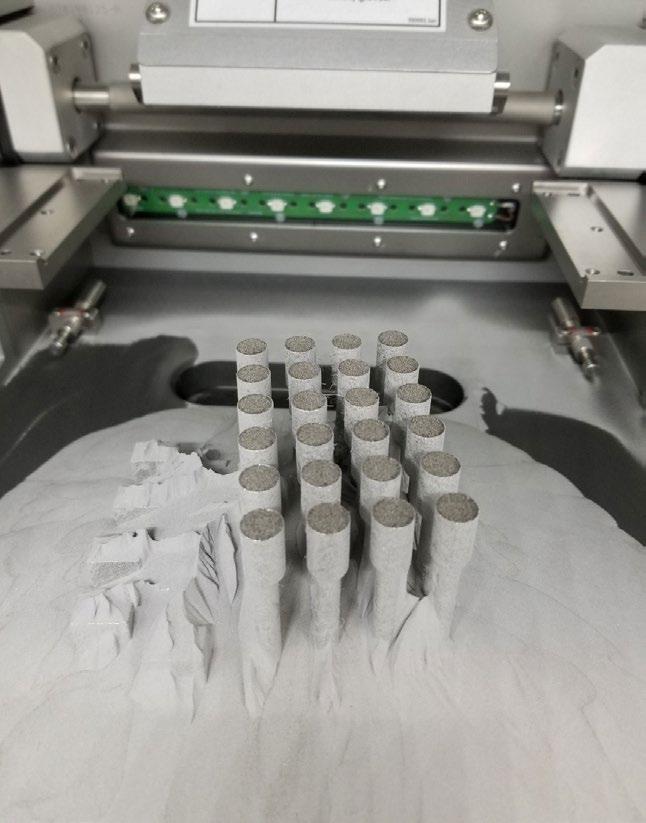
Metal Additive Manufacturing | Winter 2022 130 © 2022 Inovar Communications Ltd Vol. 8 No. 4 | contents | news | events | advertisers | print sub | e-newsletter |
Fig. 9 Net-shape tensile bars built on the SLM 125 at NanoAL. Testing is performed in-house with a Shimadzu frame
on Rapid Alloy Screening
Fig. 8 SEM image of trial powders atomised to NanoAL’s specification
NanoAL
Fig. 10 A design of experiment combining wide cross sections with thin walls, overhanging, upskin, vertical and horizontal surfaces. Each surface is characterised for roughness and each feature is measured for geometric tolerance to feedback into the parameter optimisation cycle
the same parameter window and with the same resulting properties as previous batches. The results of all atomisations are recorded in a proprietary database that is applied to future machine learning to generate new alloy designs.
Application development for end-user programmes is performed on the SLM 125 as well. Demonstrator components up to 10.2 x 10.2 x 10.2 cm (length x width x height) can be built for customers which may be used for bench scale testing or to get concepts prototyped and ideas communicated.
NanoAL runs specific development programmes on the SLM 125 to meet customer needs for thin walls, large cross sections, unsupported overhang angles, and surface finish (an example is shown in Fig. 10).
The open parameters of the SLM 125 allow the fine-tuning of build parameters directly by NanoAL engineers, without the need for back-and-forth communication with
the OEM to make changes to the profile for new alloys. In a recent programme to develop a novel alloy, NanoAL performed more than forty back-to-back builds on the SLM 125 to develop a complete profile for hatch, border, and thin wall parameters.
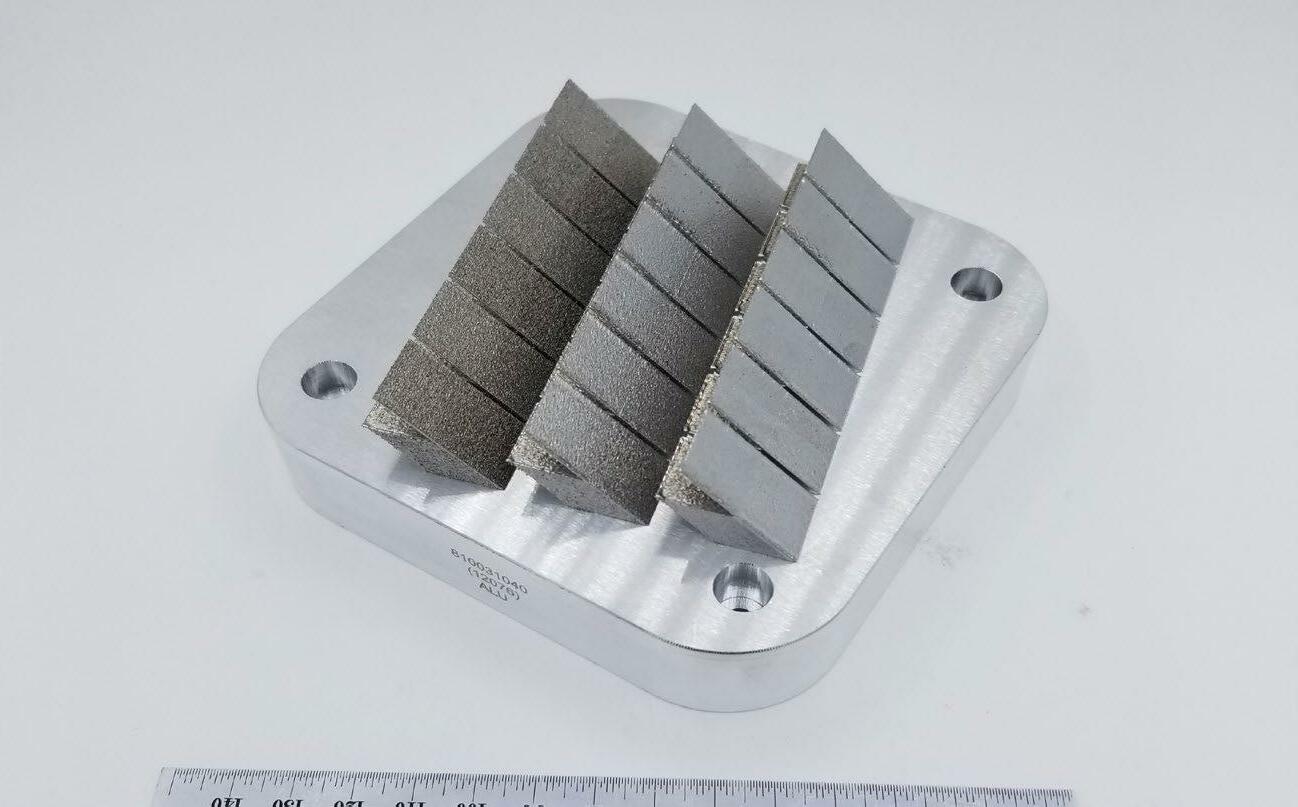
At NanoAL, several Addalloy alloys are at different stages of development, and the SLM 125 can flexibly adapt to the needs of
each. Alloys may be changed over in the machine each week, or at times the SLM 125 may be dedicated to a single alloy for up to two months of focused, programmatic work. The SLM 125 allows flexibility and agility as each alloy programme moves forward and contributes brick by brick to assemble the technical and commercial foundation for the Addalloy family of powders.
Metal Additive Manufacturing | Winter 2022 131 Vol. 8 No. 4 © 2022 Inovar Communications Ltd | contents | news | events | advertisers | print sub | e-newsletter | GETPDF
“The open parameters of the SLM 125 allow the fine-tuning of build parameters directly by NanoAL engineers, without the need for backand-forth communication with the OEM to make changes to the profile for new alloys.”
Screening
NanoAL on Rapid Alloy
Bar
Fig. 11 A cantilever bar build used for residual stress testing and to develop optimal stress relieve treatments for new alloys. Deflection along the bar is measured before and after thermal stress relief tests to determine the effectiveness of the thermal treatment
Current range of NanoAL alloys
Addalloy® 5T Addalloy® HX Addalloy® 7S
- Strength + ductility - General purpose - Auto, aero, industrial
- Strength + conductivity - Thermal management - Electronics, auto, industrial
- Maximised for strength - Lightweighting - Aero, space, industrial
Table 1 The current range of alloys available from NanoAL and their properties
Fig. 11 shows a cantilever bar build used for residual stress testing to develop optimal stress relief treatments for new alloys.
A hot topic in a hot market
Alloy development for the AM industry is a hot topic, with seemingly weekly announcements being made about new alloys, or alloys in development, by known AM players and stealth startups alike. Traditional wrought or cast alloys may not be suitable for some, or all, metal AM processes. Often, the alloys that do work with AM are not desirable for certain applications due to trade-offs between fundamental material properties and additive manufacturability.
Many hurdles exist for the adoption of AM alloys, from developing process knowledge to establishing industry standards; however, these are not necessarily unique problems specific to new alloys, as they also impact the adoption of alloys considered standard today. For PBF-LB materials, the SLM 125 is uniquely positioned to fit the needs of a developing company, research organisation, laboratory, or university, with capabilities that lend themselves to the needs of NanoAL's material engineers to advance the development of aluminium alloys designed for AM. This presents the opportunity for new alloys to enter a nascent, yet growing, market, and for parts makers to tailor the ideal alloy for their application.
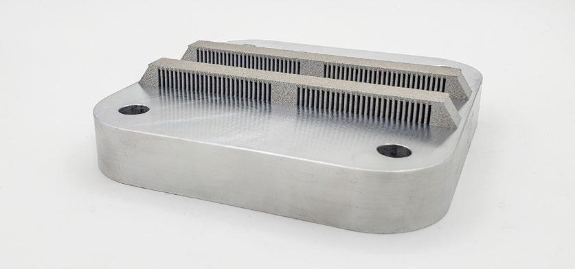
Contact
Matthew Simmers Director, NanoAL, LLC. msimmers@nanoal.com www.nanoal.com
Metal Additive Manufacturing | Winter 2022 132 © 2022 Inovar Communications Ltd Vol. 8 No. 4 | contents | news | events | advertisers | print sub | e-newsletter |
NanoAL on Rapid Alloy Screening
2 3 4 ‐
‐
‐
0 1
60
40
200204060 Deflection (mm) Distance from center (mm)
Cantilever
Stress As‐Built Stress Relieved
“Many hurdles exist for the adoption of AM alloys, from developing process knowledge to establishing industry standards; however, these are not necessarily unique problems specific to new alloys, as they also impact the adoption of alloys considered standard today.”


only magazine dedicated to MIM, CIM and sinter-based AM technologies Our exclusive deep-dive articles, company profiles, conference reports and e-newsletters are of great value to those interested in this advanced manufacturing technology for the production of complex, high volume net-shape components www.pim-international.com
The


Using the Six Sigma method to optimise metal powder spreading in PBF-LB
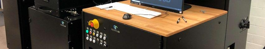
In Laser Beam Powder Bed Fusion (PBF-LB), powder is applied to the build platform by a recoater unit performing a horizontal movement. Though not often the focus of research, the quality of powder layers has a significant influence on the quality of the final part, making the powder application process highly relevant to PBF-LB's productivity and reliability. A collaborative project between the Chair of Hybrid Additive Manufacturing (HAM) at the Ruhr University Bochum and the consulting firm MTS Consulting Partner has shown how the Six Sigma method can be used to improve the process of metal powder application in the PBF-LB process.
Laser Beam Powder Bed Fusion (PBF-LB) is being used in a growing number of applications, and has taken the lead as the most visible and widely adopted of the metal Additive Manufacturing processes. Its advantages include the ability to produce small quantities of parts economically, and the ability to produce parts economically, featuring complex geometries not possible
and the parts produced [4, 5]. Since powder layers are applied and melted iteratively, the quality of the powder layers has a significant influence on part quality. In addition, the productivity of the process can be increased by reducing the time needed for powder application.
The Six Sigma method is an established management system in industry which is used for process improvement and quality management [6]. In a Six Sigma project, five phases are carried out: Define, Measure, Analyse, Improve and Control (DMAIC). Using this system -

powder with the laser beam [1–3]. and quality of the PBF-LB process
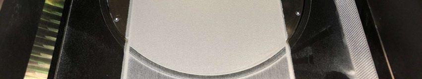
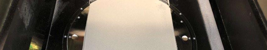
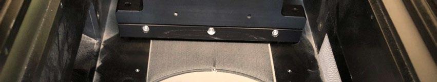
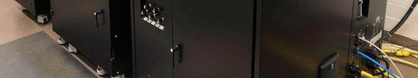
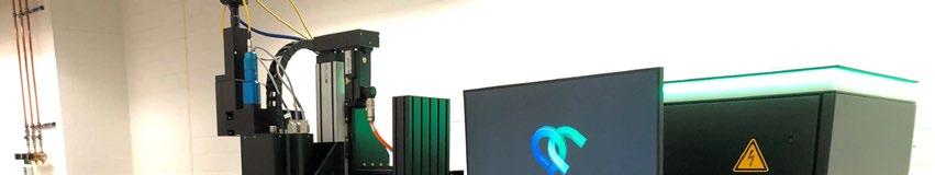
Fig. 1 Powder application in an AconityMIDI PBF-LB machine with a 120 mm wide recoater blade
Metal Additive Manufacturing | Winter 2022 135 Vol. 8 No. 4 © 2022 Inovar Communications Ltd | contents | news | events | advertisers | print sub | e-newsletter | GETPDF Six Sigma optimisation of PBF-LB
b)
Supplier Input Process Output Customer
Powder layer
Powder Supplier
Powder Powder application
Input, Process, Output, Customer (SIPOC) breakdown is used, illustrated in Table 1.
Melting of powder layer
Machine Overflow
Material Homogeneity Particle size Grooves Morphology Waves Density Defects Flowability Density Machine manufacturer
Recoater material Particle size Recoater geometry Impure particle
Built plate
Machine operator
Parameters Velocity Thickness Supply factor
Table 1 SIPOC breakdown of the powder application process
Powder recycling
The variables influencing the powder application process are the powder, with its characteristic properties; the AM machine and its equipment; and the process parameters which can be set on the AM machine. In this study, 316L stainless-steel powder (EN 1.4404) with a particle size distribution of 27-53 μ m was used. The selection of the machine, as well as the operating parameters used, were based on the machine manufacturer’s recommendations and the judgment of the authors.
atic approach, a process can be analysed using statistically validated data and improvement achieved based on fact [7]. In this project, the Six Sigma method was applied to the powder application step of the PBF-LB process.
Define: Definition of the powder application system
The powder application process studied in this Six Sigma project was assessed in an AconityMIDI PBF-LB machine from Aconity3D GmbH, Herzogenrath, Germany. Fig. 1 shows one powder layer applied with a 120 mm wide recoater blade.
In this machine, the required amount of powder for one layer is provided by the vertical movement of a supply cylinder. The powder is applied to the build platform by the recoater unit performing a horizontal movement with a built-in recoater medium. The recoater medium can be exchanged, enabling the use of different recoater materials and geometries. The vertical movement of the build cylinder determines the height of the layer. In this investigation, a 120 mm wide powder layer with a height between 30-100 μ m is applied. In the Define phase, the powder application process is described in terms of its inputs and outputs. For this purpose, a Supplier,
In the Analysis phase, these input parameters were examined in relation to their effect on the process result (output). The output of the powder application is the powder layer and the overflow of powder that results from the application. The customers of these results are the two subsequent process steps of melting the powder layer and the powder recycling process. The focus of this investigation was on the quality of the powder layer, which can be defined by various attributes. In the Measure phase, these attributes were defined and evaluated as measured parameters.
Measure: Measured parameters for the evaluation of powder application
To record the quality of the powder layer, the digital microscope VHX6000 from the manufacturer Keyence Corporation, Osaka, Japan, and the optics VH-Z100R/T at 200 X magnification are used. The microscope captures a section of approximately 1.2 x 0.9 mm and is used to evaluate the local homogeneity of the powder layer. According to the principle of focus variation, a three-dimensional profile of the powder surface is measured with the microscope. Based on this height information,
Metal Additive Manufacturing | Winter 2022 136 © 2022 Inovar Communications Ltd Vol. 8 No. 4 | contents | news | events | advertisers | print sub | e-newsletter |
Six Sigma optimisation of PBF-LB
“The focus of this investigation was on the quality of the powder layer, which can be defined by various attributes. In the Measure phase, these attributes were defined and evaluated as measured parameters...”
the surface roughness parameters arithmetic mean height (Sa) and maximum height (Sz) are determined. In addition, the volume between the measured surface and the plane which passes through the highest point of the profile parallel to the averaged surface is determined [8]. This void volume (Vo) also describes the roughness of the powder layer.
For all three measured variables, a small value stands for a homogeneous powder bed with low surface roughness. Additionally, images of the powder layer are taken with the digital camera DSC-HX400V from Sony, Tokyo, Japan. These images are examined regarding the defect characteristics local defects (De), waves (Wa) and grooves (Gr). These defect characteristics are shown as examples in Fig. 2. Fig. 3 gives an overview of the two measuring systems and the parameters they measure.
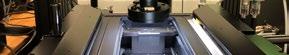


The capability of each measurement system for each of the measurands (the property to be measured) was ensured by a measurement system analysis (MSA). An MSA type 1 was carried out for the quantitative measurement parameters Vo, Sa and Sz.
Here, the empirical standard deviation ( s ) from twenty-five measurements of the same powder layer was compared with a defined tolerance field. The tolerance field was defined based on bad and good powder layers. The potential measurement


Metal Additive Manufacturing | Winter 2022 137 Vol. 8 No. 4 © 2022 Inovar Communications Ltd | contents | news | events | advertisers | print sub | e-newsletter | GETPDF
a)
d) Powder layer Local Global Void volume (Vo) Arithmetic roughness (Sa) Maximum roughness (Sz) Local defects (De) Waves (Wa) Grooves (Gr) Digital Microscope Digital Camera Six Sigma optimisation of PBF-LB
Fig. 2 Powder applications with various defect characteristics, top: entire powder bed, bottom: powder bed under 4X magnification at the location marked in red a) defect-free powder layer, b) powder layer with local defect c) powder layer with waves d) powder layer with grooves Fig. 3 Overview of the measuring
systems and parameters measured
b) c)
capability index Cg, determined according to the following equation, gives information about the repeatability of the measurement. ���������������� = 0,2 ������������������������������������������������������������������������ ���������������������������������������� 6
The qualitative measurands De, Wa and Gr were investigated by the method of attribute agreement. For this purpose, image recordings of twenty-five powder layers containing one or more of the defect characteristics were independently evaluated by three examiners. The evaluation of the images was randomised and repeated. From these evaluations, the percentage agreement of the three examiners was determined for each defect characteristic. The Cg-values and the agreement of the examiners are listed in Table 2.
The quantitative measured parameters Vo and Sz can evaluate the powder application due to their Cg-value of more than 1.00. No Cg-value can be determined for the measurand Sa, as the resolution of this measurand is not sufficient.
Waves are detected with an agreement of 100%. The agreement of local defects and grooves, on the other hand, is only 68–76%. Accordingly, defects and grooves can be identified repeatedly, but the certainty that they are detected correctly is significantly lower than for waves. At the end of the measure phase, the current process performance is recorded using the usual equipment and the usual process parameters (see Table 3). Here, the result of the measured variable Sa is also given, as this is an established parameter for describing the surface quality.
Analysis: Analysis of the powder application system
The powder application system is analysed by a statistical design of experiments (DoE). Here, the influencing variables (inputs) – geometry and material of the recoater, velocity, layer thickness, supply factor and roughness of the build platform – take on different settings. Each of the six factors is set to two different factor levels in this study. For the geometry of the recoater, a sharp version with a small contact area and a wide version with a large contact area to the powder bed are used. The recoater materials were a silicone with a hardness of 33 ShA and a tool steel. Factor settings are determined for the velocity of the recoater, the layer thickness and the supply factor based on previous studies [5,9,10]. Different surface roughnesses are generated on the build platform by a polishing process with 3 μ m diamond particles and blasting with 180–250 μ m corundum. Table 4 summarises the factor settings described.
A partial factorial, two-level experimental design was carried out according to scheme 2 6-2. This resulted in sixteen trials, realised in randomised order. Each trail comprised the evaluation
Metal Additive Manufacturing | Winter 2022 138 © 2022 Inovar Communications Ltd Vol. 8 No. 4 | contents | news | events | advertisers | print sub | e-newsletter |
∙��������
applied powder layers. Abbreviation Measurand C g/Accordance Evaluation Vo Void volume 1.28 Capable Sa Arithmetic mean height - Unfeasible Sz Maximum height 1.23 Capable De Local defects 68 % Limited Capable Wa Waves 100 % Capable Gr Grooves 76 % Limited Capable Table 2 Results of the measurement system analysis Table 3 Current process performance at usual process parameters Measurand Vo [ µ m 3] Sa [ µ m] Sz [ µ m] De Wa Gr Value 43,505,293 11.53 98.80 6 0 10 Factor Geometry Material Velocity Thickness Supply Roughness Parameter Wide Silicone 50 mm/s 30 μm 220% Turned Table 4 Factor settings for DoE Factor Geometry Material Velocity Thickness Supply Roughness Low Sharp Silicone 50 mm/s 30 μm 150% Polished High Wide Steel 200 mm/s 100 μm 290% Blasted Six Sigma optimisation of PBF-LB
of ten successively
Local analysis
The mean values of the measurands Sa and Sz show a significant correlation with the measurand Vo, with correlation coefficients between 0.880.95 (see Fig. 4).
Due to this correlation, the experiment is evaluated based on the measured parameter Vo , which has the strongest Cg-value according to the MSA. To describe the target parameter Vo , a linear regression model is generated according to the principle of forward selection at a significance level of 5%. This model has a coefficient of determination ( R2) of 77.06% and is described by the following equation. Here G stands for the recoater geometry, M for the recoater material, V for the recoater velocity, T for the layer thickness and R for the roughness of the build platform: ���������������� = 40,317,572 4,980,513 �������� 4,756,358 �������� + 108,856 �������� 66,906 �������� 1,714,008 �������� 3,649,500 ���������� �������� + 41,122 �������� �������� 54.291 �������� ��������
This model equation provides the effects of the factors on the target parameter Vo . In the Pareto diagram (Fig. 5), the standardised effects are shown in order of magnitude. The effect diagrams in Fig. 6 illustrate the directions of the effects.
The gradient of the effect lines in Fig. 6 shows the effect of the respective factor setting on the target value. The recoater velocity has the greatest effect on Vo. At low velocity,
6 8 10 12 14 16 20 30 40 50 60 70 80 70 80 90 100 110 120 130 140 20 30 40 50 60 70 80 r = 0 883 V o ( m µ m ³ ) Sa (µm) Correlation Vo with Sa r = 0 947 V o ( m . µ m ³ ) Sz (µm) Correlation Vo with Sz
Fig. 4 Correlation of the measurand Vo with the measurands Sa and Sz
Fig. 5 Pareto diagram of the effects on measurand void volume
to a sharp one. The effects of the layer thickness and the roughness of the build platform are smaller than the other effects. A large layer thickness and a rough (blasted) build platform favoured a homogeneous powder application in the experiment.
of Vo Geom etry Material Velocity (m m /s) Thickness (µm ) Roughness
Fig. 6 Effect diagrams for the measurand void volume
Metal Additive Manufacturing | Winter 2022 139 Vol. 8 No. 4 © 2022 Inovar Communications Ltd | contents | news | events | advertisers | print sub | e-newsletter | GETPDF
V
more homogeneous powder layers are measured on average than at high velocity. A recoater made of steel, in contrast to one made of silicone, leads to more homogeneous powder layers. The same applies to a wide recoater geometry compared G T R S
M
0 1 2 3 4 5 6 7 8 9 10 11 12 13 14 15 16 1 98 Standardized Effect Ef f ect signif icant V: Velocity M: Material G: Geometry T: Layer Thickness R: Roughness S: Supply Factor
50
40 45 50 55
M
f V
(
µ
)
Six Sigma optimisation of PBF-LB
Pareto Diagram of Vo sharp wide Silicone Steel
200 30 100 polished blasted
60
e a n o
o
m .
m ³
Effect
Diagrams
The supply factor has no significant effect on the measurand Vo. In addition to the effects of the individual factors, interaction effects occurred. These become apparent through the different effects of the recoater geometry depending on the material, velocity and powder layer thickness. In Fig. 7, the interaction effects can be interpreted based on the different gradients of the effect lines.
The effect of the recoater geometry is significantly greater with recoaters made of steel than with those made of silicone. In addition, the effects show different directions. On average, the smallest void volume is achieved with the wide recoater made of steel. The geometry of the recoater hardly shows any effect at a high recoater velocity. At a low velocity, on the other hand,
more homogeneous powder layers are achieved when using the wide geometry. Layer thickness amplifies the effect of the recoater geometry, as there is a stronger effect with greater layer thicknesses.
Global analysis
When evaluating the qualitative parameters De, Wa and Gr, the number of layers in which the respective defect characteristic occurred is considered. There is no significant correlation between the local defects and factors (inputs). Waves occur as a function of the recoater velocity and the recoater used. The diagrams in Fig. 8 show the number of layers in which waves occurred for each trail, in relation to the recoater’s velocity, material and geometry.
The number of layers with waves is significantly lower at the recoater velocity of 50 mm/s than at 200 mm/s. At the low recoater velocity, no waves occur except in one trail. Under the high velocity, except for two trials (marked red), all trials show waves in each of the ten layers. In these two trials, the application was performed with a wide silicone recoater. Since these trials have a large void volume, there is a possibility that the roughness and inhomogeneity of the powder layer is covering up the waves. Grooves also shows
Metal Additive Manufacturing | Winter 2022 140 © 2022 Inovar Communications Ltd Vol. 8 No. 4 | contents | news | events | advertisers | print sub | e-newsletter |
sharp w
30 40 50 60 M e a n o f V o ( m . µ m ³ ) Vel
50
50
0 2 4 6 8 10 L a y e r s w i t h G r o o v e s
sharp
0 2 4 6 8 10 L a y e r s w i t h G r o o v e s
50
0 2
L a y e r s w i t h W a v e s
L a y e r s w i t
s
Six Sigma optimisation of PBF-LB
ide sharp w ide sharp w ide
ocity
m m /s 200 m m /s Thickness 30 µm 100 µm Material Silicone Steel Interaction Diagrams of Vo Fig. 7 Interaction diagrams for the measurand void volume Fig. 9 Occurrence of grooves as a function of velocity and recoater Fig. 8 Occurrence of waves as a function of velocity and recoater
200
Velocity (mm/s)
wide sharp wide Steel Silicone
Recoater
200
4 6 8 10
Velocity (mm/s) sharp wide sharp wide Steel Silicone 0 2 4 6 8 10
h W a v e
Recoater
a dependence on the recoater velocity and the recoater used. Analogous to waves, in Fig. 9 the number of layers with grooves is shown for each of the trials in relation to the velocity and the recoater.
At the recoater velocity of 50 mm/s, significantly more layers with grooves occur than at 200 mm/s. A comparison of the different recoaters shows that fewer grooves occurred using a recoater made of steel than one made of silicone. In particular, the steel recoater with the wide geometry generated the fewest grooved layers. A comparison of the individual trials showing the number of grooves, number of waves and the void volume is given in Fig. 10.
The representation of the grooves against the waves shows that two trials have no waves and only a few grooves (marked in red). The consideration of the sum of waves and grooves in relation to the mean void volume shows that, in these two trials, significantly more homogeneous powder layers were achieved. Both trials were carried out at a recoater velocity of 50 mm/s using the wide steel recoater.
Improve: Optimisation of powder application
In the Improve phase, the findings of the Analysis phase are used to optimise the process. The local quality of the powder coating is highest at a recoater velocity of 50 mm/s, using a wide steel recoater. In addition, no waves and only a few grooves are generated with these settings. In order to verify the improvement of the powder application process, a trail is now carried out with the appropriate settings for the influencing variables. The results of this trail are compared with those of the current process performance in Table 5.
Based on the measured parameters, the quality of the powder
layer was significantly improved at the same recoater velocity. This applies particularly to the local homogeneity of the powder layer, which is described by the measured parameters Vo, Sa and Sz. The increase in local defects can be explained by the fact that small local defects are more noticeable in a homogeneous powder layer than in a less homogeneous one. Local defects are less critical compared to periodic defects such as grooves or waves, as they do
not extend over the entire powder bed. The occurrence of grooves could be eliminated with the modified settings.
Control: Project documentation
The Control phase serves to ensure the improvement of the process. For this purpose, a documentation of the project was created that summarises the results of the
process
optimisation
Metal Additive Manufacturing | Winter 2022 141 Vol. 8 No. 4 © 2022 Inovar Communications Ltd | contents | news | events | advertisers | print sub | e-newsletter | GETPDF
Vo
Fig. 10 Comparison of number of grooves, number of waves and void volume of sixteen trials 0 2 4 6 8 10 0 2 4 6 8 10 0 2 4 6 8 10 12 14 16 20 30 40 50 60 70 L a y e r s w i t h G r o o v e s Layers with W aves Grooves vs. Waves (4x) (5x) V o ( m µ m ³ ) Sum of W aves and Grooves
vs. Waves and Grooves
Table 5 Comparison of the measurands of current
performance with those after
Measurand Vo [ µ m 3] Sa [ µ m] Sz [ µ m] De Wa Gr
Before 43,505,293 11.53 98.80 6 0 10 After 27,787,009 6.93 65.40 10 0 0 Change [%] -36.1 -39.9 -33.8 +66.7 0 -100
Six Sigma optimisation of PBF-LB
“Based on the measured parameters, the quality of the powder layer was significantly improved at the same recoater velocity. This applies particularly to the local homogeneity of the powder layer, which is described by the measured parameters Vo, Sa and Sz...”
analysis phase. This includes a control plan with recommendations for avoiding defect characteristics and increasing local homogeneity. Based on the described regression model, it can be predicted which factor settings lead to which quality of the powder application. At the end of the project, the measurement data and the documentation were handed over to the person responsible for the AM machine to enable the setting of the ideal powder application parameters.
Summary and outlook
This study shows how the powder application process step was successfully optimised using the Six Sigma method. The process, divided into the five DMAIC phases, represented a systematic and structured approach. Powder application was treated as a separate process, the result of which is described by validated measurands. The effect of the influencing variables on this process was analysed with statistical methods, whereby knowledge about the process was obtained.
Based on these facts, an improvement in the quality of the powder application was achieved and ensured in the long term. With regard to the economic efficiency of the PBF-LB process, it is important to increase productivity. This can be realised by a shorter application time and, thus, a higher recoater velocity.
Since increasing the recoater velocity leads to a decrease in the quality of the powder layer, it must be investigated how high the quality of the powder layer has to be in order to produce components with acceptable quality. Future investigations on this topic are planned. In this context, other powder materials, as well as other application systems, will also be investigated. In line with these plans, a powder test rig is currently being developed.
Authors
Tim Robert Brocksieper
Chair of Hybrid Additive Manufacturing, Ruhr-University Bochum, Bochum, Germany tim.brocksieper@ruhr-uni-bochum.de
Nick Hantke
Chair of Hybrid Additive Manufacturing, Ruhr-University Bochum, Bochum, Germany nick.hantke@ruhr-uni-bochum.de
Prof Dr-Ing Jan T Sehrt
Chair of Hybrid Additive Manufacturing, Ruhr-University Bochum, Bochum, Germany jan.sehrt@ruhr-uni-bochum.de
Dr Dietmar Stemann
MTS Consulting Partner, Werl, Germany
stemann@mts-consultingpartner.com
References
[1] C D Boley, S A Khairallah, A M Rubenchik, Calculation of laser absorption by metal powders in additive manufacturing, Appl. Opt. 54 (2015) 2477–2482. https://doi. org/10.1364/AO.54.002477
[2] A V Gusarov, J -P Kruth, Modelling of radiation transfer in metallic powders at laser treatment, International Journal of Heat and Mass Transfer 48 (2005) 3423–3434. https://doi.org/10.1016/j. ijheatmasstransfer.2005.01.044
[3] R Mertens, S Dadbakhsh, J van Humbeeck, J -P Kruth, Application of base plate preheating during selective laser melting, Procedia CIRP 74 (2018) 5–11. https://doi. org/10.1016/j.procir.2018.08.002
[4] S E Brika, M Letenneur, C A Dion, V Brailovski, Influence of particle morphology and size distribution on the powder flowability and laser powder bed fusion manufacturability of Ti-6Al-4V alloy, Additive Manufacturing 31 (2020). https://doi. org/10.1016/j.addma.2019.100929
[5] V Seyda, Werkstoff- und Prozessverhalten von Metallpulvern in der laseradditiven Fertigung, Springer Vieweg, Berlin, Heidelberg, 2018.
[6] J Antony, R Snee, R Hoerl, Lean Six Sigma: yesterday, today and tomorrow, IJQRM 34 (2017) 1073–1093. https://doi.org/10.1108/ IJQRM-03-2016-0035
[7] ISO 13053-1:2011-09, Quantitative methods in process improvement: Six Sigma - Part 1: DMAIC methodology.
[8] A Mussatto, R Groarke, A O’Neill, M A Obeidi, Y Delaure, D Brabazon, Influences of powder morphology and spreading parameters on the powder bed topography uniformity in powder bed fusion metal additive manufacturing, Additive Manufacturing 38 (2021). https://doi.org/10.1016/j. addma.2020.101807
[9] C N Hulme-Smith, V Hari, P Mellin, Spreadability Testing of Powder for Additive Manufacturing, Berg Huettenmaenn Monatsh 166 (2021) 9–13. https://doi.org/10.1007/ s00501-020-01069-9
[10] Z Snow, R Martukanitz, S Joshi, On the development of powder spreadability metrics and feedstock requirements for powder bed fusion additive manufacturing, Additive Manufacturing 28 (2019) 78–86. https://doi.org/10.1016/j. addma.2019.04.017
Metal Additive Manufacturing | Winter 2022 142 © 2022 Inovar Communications Ltd Vol. 8 No. 4 | contents | news | events | advertisers | print sub | e-newsletter |
Six Sigma optimisation of PBF-LB
METTALURGY & PARTICULATE MATERIALS


Register here PM23
ON
Powder Metallurgy (PM) is a technique in which particulate materials are blended, compacted and sintered to the desired end-use product Few of the advantages the PM offers over other metal forming technologies such as forging and metal casting are advantages in material utilization, shape complexity, near-net-shape dimensional control, etc Over the past few years, PM has been widely recognized as a preferred process for producing high-quality parts for diversified applications The development of lifestyle & health devices, VVT, hybrid vehicles, electric vehicles, fuel cells, catalytic converters, composite electrical contacts, advanced sensors, light weight components and thermoelectric devices have been made possible by the use of several technologies that comprise the science & practice of PM This conference addresses these and related developments by way of presentations made by experts in each field The conference attendees will have access to more than 100 technical presentations from worldwide experts presenting the latest technology developments in this fast-growing field Also, they will have a golden opportunity to get their research published in renowned international journals The concurrent 48th Annual Technical Meet of PMAI provides a platform for industrialists, researchers and students from scientific establishments & academia to present their work
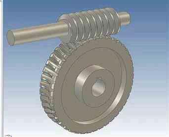
PM 2023
INTERNATONAL CONFERENCE
POWDER
(PM 23) & EXHIBITION & 48th ANNUAL TECHNICAL MEETING OF PMAI (13th -15th March 2023)
www.pmai.in
Submit Abstract on EASYCHAIR
Why attend PM 23? Mr.
(+91 9096943327) Mr.
(+91 9820951180) convener@pmai.in All Conference Related Updates will be available on PMAI website www.pmai.in Start
Submit your abstract at EASYCHAIR PMAI TRANSACTIONS OF POWDER METALLURGY ASSOCIATION OF INDIA HOTEL LALIT MUMBAI Sahar Airport, Navpada Marol Andheri East, Mumbai Maharashtra India 400059 ❖ Industrial
technology forauto,
parts ❖ Powder
❖ Additive
❖ Hard
❖ Development of
&
for
applications ❖ Technical Ceramics &Composites ❖ Vehicle weight reduction ❖ Porous materials ❖ PM in Electric
❖ PM in bio-medical apps &devices ❖ Powder production & characterization ❖ Compaction & other forming processes ❖ Binder & feedstock development ❖ Hot Isostatic Pressing(HIP) ❖
❖
❖
❖
❖
❖
❖
❖ Refractory
❖ Magnetic
❖ Materials
❖ Materials
& storage ❖ Functionally
materials ❖ Ceramics & composites * Only complete papers that are received by the deadline and presented at the conference will be peer reviewed and then considered for the publications Venue: Conference Secretariat Topics: Important Dates: Publication Partners:
Swapnil Sable
K.S.Samant
of Abstract Submission & Registration 05th Nov, 2022 Deadline for Submission of abstract 05th Jan, 2023 Acceptance of abstract 31st Jan, 2023 Submission of the complete paper 28th Feb, 2023
PM (press & sinter)
electrical and machine
Injection Molding (MIM &CIM)
Manufacturing(AM)
Metals & Diamond Tools
materials
alloys
emerging
Vehicles(EVs)
Laser sintering, cladding and coating
Testing & data mining
Sintering & post sintering processes
Spark plasma & hot press sintering
Dimensional control
Heat treatment & surface engineering
Aluminum sintering
metals
materials
for aerospace, defense & nuclearapps
for energy generation
gradient
CAESARS PALACE
technical program

TRADE EXHIBIT
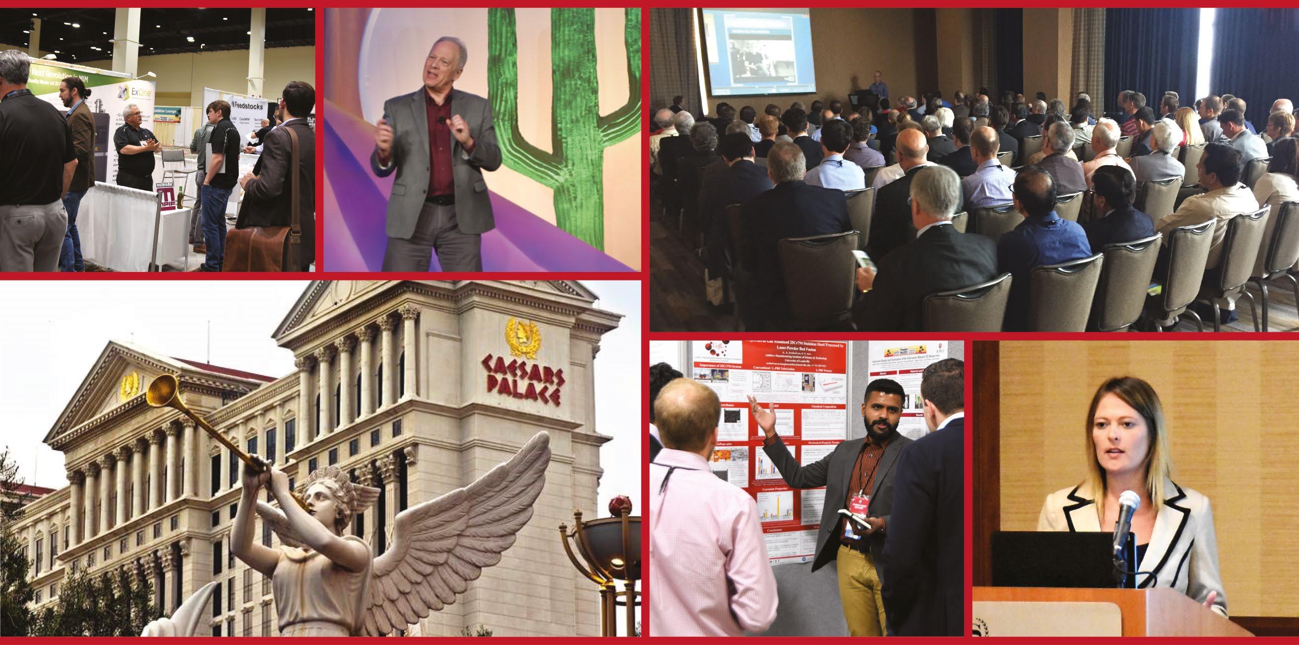
LAS VEGAS Metal Powder Industries Federation APMI International Visit PowderMet2023.org or AMPM2023.org PowderMet2023 International Conference on Powder Metallurgy & Particulate Materials AMPM2023 Additive Manufacturing with Powder Metallurgy PowderMet2023/AMPM2023 June 18–21, 2023 • Caesars Palace, Las Vegas JUNE 18–21 • LAS VEGAS
Attendees will have access to hundreds of technical presentations from worldwide experts on the latest research and development.
The largest annual American exhibit showcasing leading suppliers of powder metallurgy and metal additive manufacturing powders, equipment, and products. Register Today and save!
Insights from R&D to part production: How CT analysis can advance metal Binder Jetting
In the race to optimise AM technologies for the creation of both breakthrough designs and direct part replacements, it is more necessary than ever that companies have access to the deep insights and data needed to advance part designs and processing at every phase of product development. Thanks to its ability to provide these insights non-destructively and in great detail, CT analysis provides an invaluable tool for the advancement of AM processes and their adoption. Philip Sperling, Product Manager AM at Volume Graphics, explains how CT analysis can advance the development and adoption of metal Binder Jetting (BJT).
No manufacturing process is static – either weaknesses and operation costs are addressed through continuous improvement to the core process, or competing technologies step in, upping speed, quality, costs and viability. This is certainly true in the Additive Manufacturing sphere, where Laser Beam Powder Bed Fusion (PBF-LB) is prominent and approaches such as metal Binder Jetting (BJT) and other metal AM processes seek to expand beyond their niches and make gains in series production.
Today, at private R&D sites and on factory floors, AM machines are evolving at a fierce rate, fighting to either dominate in a specialised sector or serve as a universal tool in the same style as Computer Numerical Control (CNC) machines.
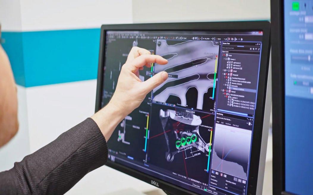
Metal Binder Jetting is a fastemerging process, promising new performance and functionality and higher productivity within its target markets. It also hopes to provide the same manufacturing agility as the more established PBF-LB process, whilst complementing traditional
shape-forming and finishing technologies. At present, metal BJT typically utilises stainless steel 316L and 17-4 PH to address performance goals for industries such as automotive and aerospace, targeting, in particular, hydraulic components.
To restate a point: the AM industry is changing and improving at a blistering pace, both in the
speed and size of parts made, their geometrical and metallurgical accuracy, and their repeatability for quality and volume manufacturing. Oft-repeated lists of strong ‘advantages’ and ‘disadvantages’ are expected to change as improving Additive Manufacturing technologies expand capabilities and grow past their entry markets.
facility
Metal Additive Manufacturing | Winter 2022 145 Vol. 8 No. 4 © 2022 Inovar Communications Ltd | contents | news | events | advertisers | print sub | e-newsletter | GETPDF CT analysis in Binder Jetting
Fig. 1 The Volume Graphics team inspects a CT scan of a part at its Heidelberg
90
Fig. 2 Low-resolution scan showing (90 µm and 30 µm) layer thickness of a green binder jetted part. Analysis reveals distinction between layers, different compactness, porosity, and high-density material accumulations — ahead of the debinding and sintering process
all AM machines. But, in most cases, AM provides better part density than castings, and metal BJT, at least in some quarters, is currently on a rigorous path to address porosity and related stresses through use of CT scanning and software analysis.
The role of CT analysis in BJT part development
90
Fig. 3 Low-resolution CT scan of the green BJT part showing horizontal lines corresponding to spacing of the print head nozzles; voids created by impact of droplets; and 3 X larger amount of binder — causing a downward flush of finer particles from the top to the bottom layer
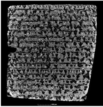
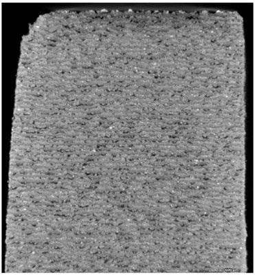
For instance, the argument that support structures in PBF-LB are a key disadvantage, while generally true, is not universally applicable. A newly available generation of advanced PBF-LB machines have nearly negated this issue, with potential zero-degree wall angles achieved through careful end-to-end process control.
Porosity is a common challenge and a ‘pass-fail’ measurement for
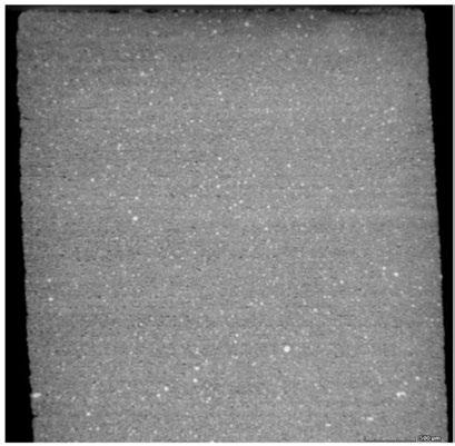
Computed Tomography (CT) analysis provides insights at every phase of product development and manufacture. Because of its ability to view interior regions of a part nondestructively, it provides valuable quantitative data on specific, critical and overall regions of a part and/ or assembly. High-performance AM components usually exhibit fresh and quite novel geometries. There are unique stresses and vulnerabilities inherent in creating purely functiondriven passageways and features, be it with PBF-LB or BJT.
Unlike the laser-induced heat approach of PBF-LB, Binder Jetting is driven by the interaction of powder particles, the compaction by the roller and the application of the adhesive binder. Parts are later thermally processed in two-stages to burn off the binders, reduce porosity and achieve target strengths and the desired microstructure. In the first stage of the two-step process, the
'green' part is debound. Next, a higher temperature is applied (usually in the same furnace) to sinter the part to its final strength. Achieving a strong green part is also crucial as prior to debinding, excess powder has to be removed and the part handled.
With evolving and mature AM technologies alike, ongoing process knowledge, process inspection, and final control are paramount to success. In order to reach commercial reliability, every approach has had to move away from black-art practices and ‘recipes’ that can’t be replicated machine to machine – or even batch to batch on the same machines. Here is where CT analysis can help developers understand process causality and interrelated factors that influence outcomes. Pinpointing causes and effects can serve to aid in the use and development of sensors, feed rollers, build heads, feeders, binders, and overall operating parameters. Analysis also greatly helps in effectively addressing shrinkage, distortions, brittleness and porosity.
Early process parameter development
Early insight into build process behaviours and conditions that lead to observable and measurable trial outcomes is crucial for shortening development cycles and establishing long-term operating parameters that are reliable and deliver the highest level of productivity and, thus, commercial success. Reaching results faster in early development helps compress all the follow-on stages of product creation. It also establishes a sound methodology for continuous improvement and future expansion of machine features and capabilities.
CT analysis enables a deeper understanding in the development of metal BJT process parameters (e.g., when the user is evaluating different combinations of powder, layer thickness and binder saturation). Other testing methods, while available, are very limited and don’t give a deep volumetric insight into the green part.
Metal Additive Manufacturing | Winter 2022 146 © 2022 Inovar Communications Ltd Vol. 8 No. 4 | contents | news | events | advertisers | print sub | e-newsletter |
Direction of print head
µm layer thickness
30 µm layer thickness
Build direction Z
µm layer thickness green body
CT analysis in Binder
Jetting
For development of early, critical machine parameters, low-resolution CT slice images (as shown in Figs. 2, 3) have proven to be excellent for overview and initial analysis. Highresolution CT slice images are comparable to microsection images and were good for targeted analyses. 90 μ m layer thicknesses revealed larger inhomogeneities that later led to poorer quality parts in the postsintering stage.
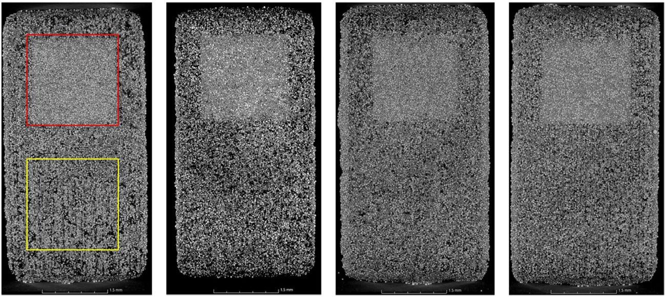
One interesting effect identified through CT analysis of binder jetted parts has been the tendency for segregation of fine powder particles in the bottom layers of a build, which leads to higher porosity (Fig. 4). This problem is caused by the tendency of finer particles to sometimes agglomerate. Understanding this behaviour allows engineers to evaluate original powder sizes in relation to layering methods and binder mixes.
Later process parameter development
The production of BJT parts incorporates several stages. These include the initial build (sensitive to layering heights, binder amounts and powder
quality); low-temperature debinding (still a highly porous state for the part); and longer-cycle, higher-heat sintering to further bond the metal, reduce porosity and eliminate binder additives.
As with early-stage CT analysis, each phase of metal BJT part development can be measured via one-off scans, and batch or inline automated inspections, according to circumstances such as production controls for aerospace-spec parts. Together, early and mid-process tracking reveal these main findings:
• Density variations can be observed in sintered metal BJT parts. These variations can be traced back to the powder
application by roller, the binder application itself, and the powder-binder interactions
• Binder application can lead to segregation of powder particles in one layer
• The binder application process can lead to porosity in green and sintered parts due to droplet impact. Higher binder saturation levels can compact the particle structure in green parts due to capillary forces and mechanical impact effects
With final part density, strength, and geometric accuracy so important to commercialisation —and shrinkage rates and other process
Metal Additive Manufacturing | Winter 2022 147 Vol. 8 No. 4 © 2022 Inovar Communications Ltd | contents | news | events | advertisers | print sub | e-newsletter | GETPDF
Fig. 4 Analysis of the XY-plane in red, measures powder density without the binder imprint. The yellow area below it measures the powder density with the binder imprint. The results show the segregation effect of finer particles and the resulting porosity
“One interesting effect identified through CT analysis of binder jetted parts has been the tendency for segregation of fine powder particles in the bottom layers of a build, which leads to higher porosity.”
CT analysis in Binder Jetting
100 µm 35% 100 µm 60% 50 µm 35% 50 µm 60%
impacts affecting quality and yield — in-process inspection and knowledge collection is fundamental to success.
Benchmarking and prediction

Two compatible CT software analysis approaches can help in early process analysis and geometric compensation: measurement-based and simulation-based. Measurement-based analysis serves to benchmark stages and conditions in the process leading to quantification of approaches and goals, improvements, and establishment of required, final part geometries. This approach includes comparisons between the nominal and the actual CAD tolerances and geometries against the as-manufactured part to show deviations (Fig. 5).
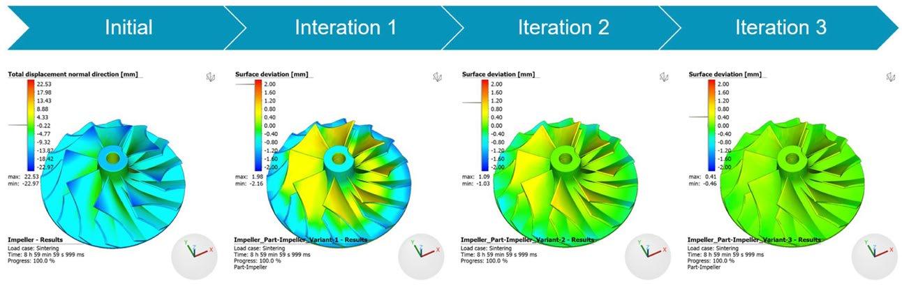
The simulation-based approach relies on prior process simulation of the shrinkage (e.g., in Simufact Additive). In such software solutions, the part geometry and shrinkage occurring during the sintering process can be simulated, allowing the part geometry to be suitably adjusted to affect different shrinkage behaviour in the
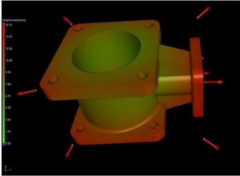
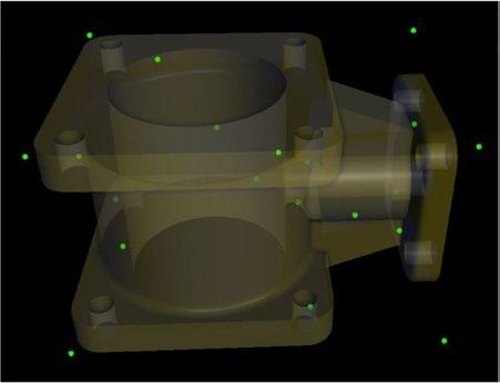
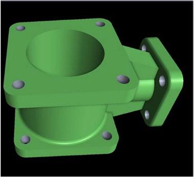
X,Y and Z axes. For more complex part geometries, the simulationbased approach can be used to make increasingly detailed adaptations for complex part designs (Fig. 6).
Many challenges can be addressed using simulation, including shrinkage compensation and process adjustments, going back to powder sizes
Metal Additive Manufacturing | Winter 2022 148 © 2022 Inovar Communications Ltd Vol. 8 No. 4 | contents | news | events | advertisers | print sub | e-newsletter |
Fig. 5 This sequence of images (left to right) shows the nominal part geometry, a scan of the sintered part, and the simulated geometry of the earlier green part
Fig. 6 Simulation allows individual process stages to be tested virtually and iteratively for design adjustments related to shrinkage, for example, and predictions to be made of final part conformance to specifications
“Advantages of the measurement-based compensation software approach are (1) compensation for distortions that are beyond the accuracy of simulation and (2) the ability to tackle non-uniform distortions within the build space and sintering furnace, providing machine repeatability.”
CT analysis in Binder Jetting
Effectiveness of the solution
Simulation based compensation (Simufact)
0.05
Dimensional requirements
0.2 0.7
Measurement based compensation (Volume Graphics) CAD baseline distortion
Absolute distortion value to compensate (mm)
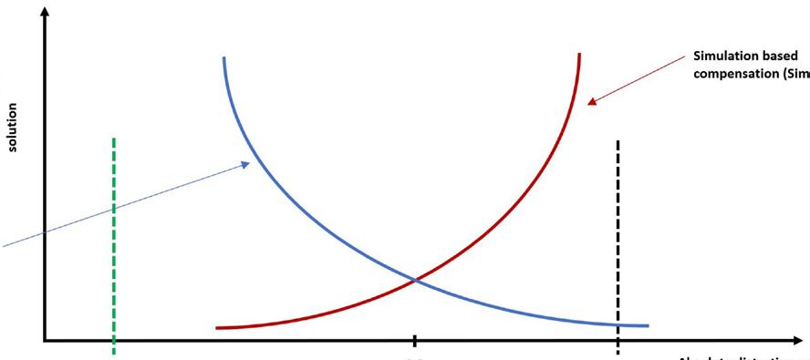
Fig. 7 The dimensional requirement set in the CAD model and the absolute distortion rate needing compensation
and anomalies in porosity through to aspects of curing and post-processing.
Advantages of the measurementbased compensation software approach are (1) compensation for distortions that are beyond the accuracy of simulation and (2) the ability to tackle non-uniform distortions within the build space and sintering furnace, providing machine repeatability.
Advantages of simulation-based compensation are (1) predicatively solving manufacturing problems, (2) identifying an orientation/support concept that is fit for distortion compensation and (3) the ability to iterate designs free of the cost of physical tests and numerous trial runs.
A solution for R&D and production
CT software analysis of scanned data for Additive Manufacturing processes, such as Binder Jetting, provides the insights and actionable information needed to shave years off of development efforts. It can also help to ensure that production examples reach the series quality demanded by customers. In the race to use AM for creation of breakthrough designs and much-needed, quickly produced, direct-part replacement markets, CT analysis software offers the depth, breadth and level of automation required for advancing new and evolving Additive Manufacturing technologies.
Author
Philip Sperling Product Manager Additive Manufacturing, Volume Graphics Heidelberg, Germany www.volumegraphics.com
Metal Additive Manufacturing | Winter 2022 149 Vol. 8 No. 4 © 2022 Inovar Communications Ltd | contents | news | events | advertisers | print sub | e-newsletter | GETPDF
CT
in Binder
analysis
Jetting
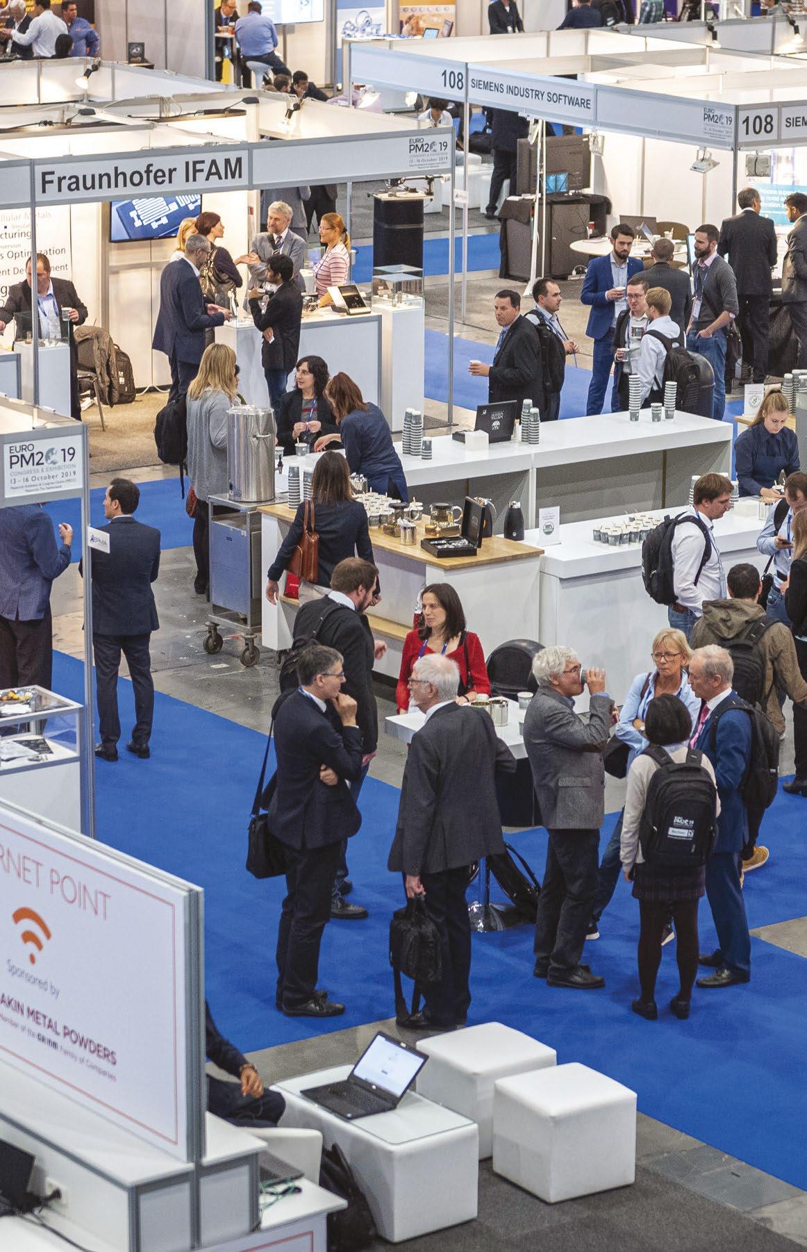
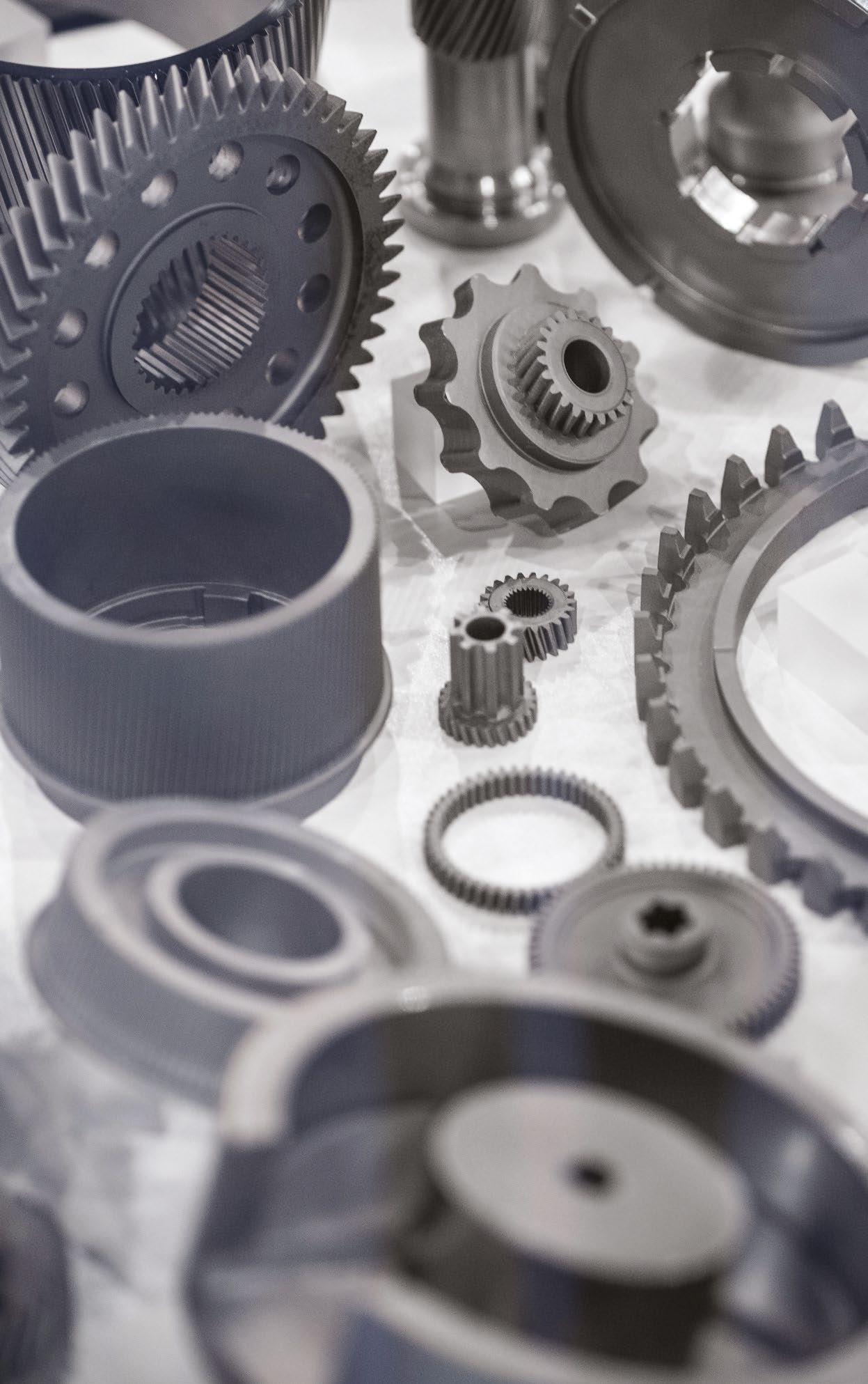
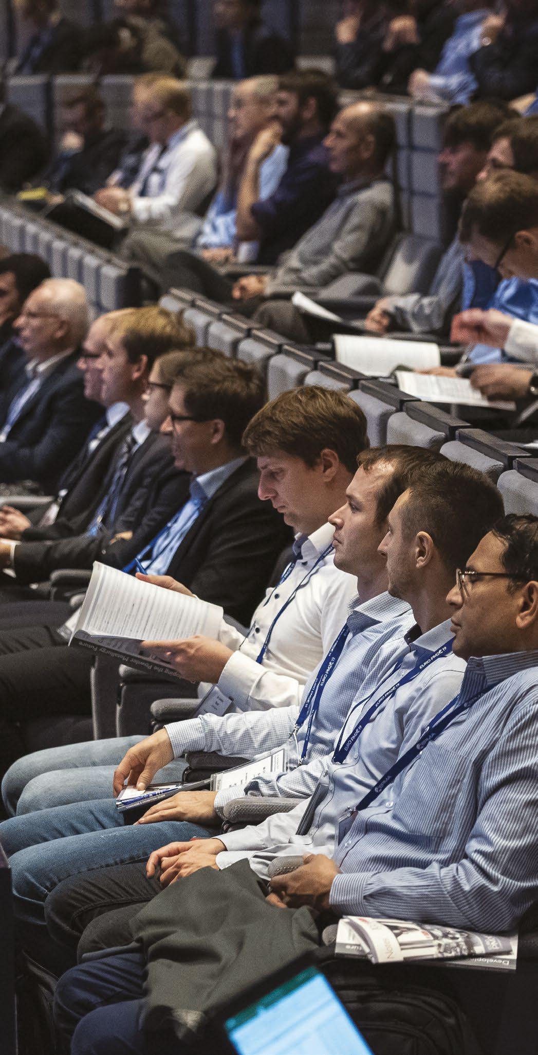


Congress & Exhibition europm2023.com 1 - 4 October 2023 Lisbon, Portugal EURO POWDER METALLURGY FIRST ANNOUNCEMENT
Corrosion and wear resistance of materials processed by beam-based AM technologies
A technical session at the World PM2022 Congress & Exhibition, organised by the European Powder Metallurgy Association (EPMA) and held in Lyon, France, October 9-13, 2022, focused on the corrosion and wear resistance of materials processed using beam-based Additive Manufacturing. This session comprised three papers which looked at ways to improve these properties – both particular pain points for AM's wider adoption – by way of chemical-mechanical surface polishing, adjusted laser power, and the development of new, wear-resistant alloys for AM. Dr David Whittaker reviews the presented papers.
Chemical-mechanical
surface polishing to improve mechanical performance and corrosion resistance
The first paper presented in this session came from Agustin Diaz and Patrick McFadden from REM Surface Engineering, USA, and Matias Garcia-Avila and John Scovill of ATI Specialty Materials, USA, and addressed the surface texture optimisation of metal additively manufactured components by chemical-mechanical polishing to improve mechanical and corrosion resistance [1].
Fatigue performance and corrosion resistance requirements are two of the most problematic aspects in the Additive Manufacturing field. The main reasons for failures in these two aspects are the close relationship between surface texture and the usual surfacerelated defects (SRD), such as partially melted/sintered powder,
v-notches, remnants of melt pools (fish scaling), and remaining support structures. These defects can reduce corrosion performance and cause fracture initiation sites. For most medical, aerospace, space exploration, and many other applications, these defects can limit applicability.
The main objective of the reported study was to showcase a combination of surface finishing techniques developed for metal AM workpieces, capable of improving surface waviness, roughness, corrosion resistance, and mechanical properties under cyclic loading.
Fig. 1 The plenary session at World PM2022 in Lyon, October 2022 (Image PIM International)
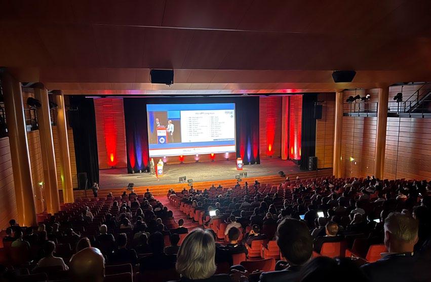
Metal Additive Manufacturing | Winter 2022 151 Vol. 8 No. 4 © 2022 Inovar Communications Ltd | contents | news | events | advertisers | print sub | e-newsletter | GETPDF World PM2022: corrosion and wear resistance
Fig. 2 Microscope images at 100 X magnification of the surface texture progression at different levels of surface material removal of PBF-LB (Ti-6Al-4V), with near-surface porosity problems exposed during the CP process (a–d), and 3D microscope image of the surface at 150 µ m surface metal removal (e) [1]
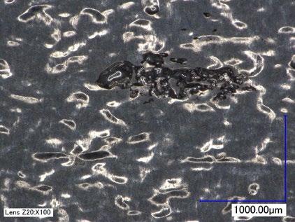
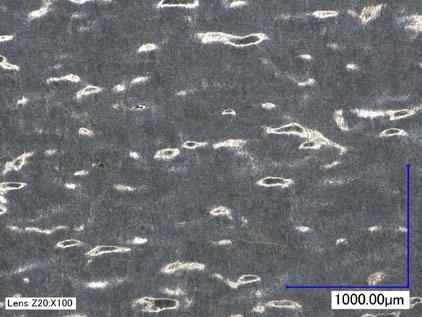
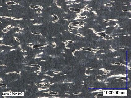
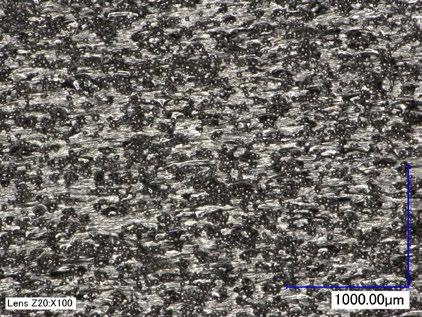
For components additively manufactured via Powder Bed Fusion (PBF), the stress raisers that compromise fatigue lifetime are largely hidden below an accumulation of partially melted/sintered powder at the surface. It is well known that the cause of early failure is the accumulation of stress raisers at the surface, such as extreme surface roughness and v-notches. The other aspect that is often associated with surface roughness is the material’s corrosion resistance. Surface texture features in PBF components can be associated with different corrosion issues (e.g., pitting corrosion, crevice corrosion, or fretting). It has also
been established that, due to the strong correlation between SRD and the corrosion resistance of components, it can be anticipated that the corrosion resistance would be significantly improved after an appropriate surface finishing operation.
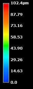
The other aspect that compromises structural integrity of PBF components is the accumulation of sub-surface porosity at the near surface. A contour scan, comprising one or more electron or laser beam passes, can be employed during the build process to delimit the part surface from the part’s internal structure. When the contour process parameters are not optimised,
sub-surface porosity is generated, reducing the relative density of the material and compromising mechanical performance. Also, there are instances where the issue is not within the contour scan line, but, instead, is within the overlapping settings between the contour and the hatching pass. Failure to produce a successful overlap between these two passes causes sub-surface porosity and lack of fusion at the near-surface. However, this internal porosity can be healed with a proper Hot Isostatic Pressing (HIP) procedure. Therefore, any subtractive surface finishing operation should improve mechanical and corrosion resistance if a post-processing heat treatment capable of remediating the sub-surface porosity, such as HIP, is performed beforehand.
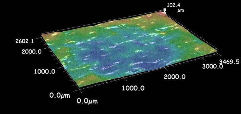
Many of the potential post-process methods for the improvement of surface texture are inapplicable for AM components, because of the technology’s freeform capability and resultant complex geometries, including internal passages, cavities and channels.
The reported work has focused on the effects of surface finishing of PBF-built metal components, using a combination of technologies that have demonstrated the potential to eliminate or reduce surface-related defects, involving chemical-mechanical polishing. Examples of such finishing treatments for Electron or Laser Beam Powder Bed Fusion (PBF-EB and PBF-LB, respectively), were showcased to demonstrate the process’s capabilities. Case studies for PBF-EB Ti-6Al-4V, PBF-LB GRCop42, and PBF-LB IN625 were selected as examples.
The specimens used for the study were additively manufactured vertically (90° with respect to the building platform) using the two different PBF types. Specimens were additively manufactured with and without contours.
The surface finishing process was performed by REM Surface Engineering, using their Extreme ISF Process®. This process combines a chemical polishing (CP) operation
Metal Additive Manufacturing | Winter 2022 152 © 2022 Inovar Communications Ltd Vol. 8 No. 4 | contents | news | events | advertisers | print sub | e-newsletter |
World PM2022:
resistance a)
c) 150
e)
b)
d)
corrosion and wear
As-built
µm
150 µm
100 µm
175 µm
followed by a chemical mechanical polishing process (CMP). The CP was performed by immersion in a robotcontrolled chemical polishing bath. The CMP was performed in a 30 L circular vibratory bowl with a mix of non-abrasive ceramic media. The chemistry and dosing used for CP and CMP, as well as the media mix composition, shapes, and sizes, are the proprietary information of REM Surface Engineering and were not disclosed in the presentation.
Turning to the first of the case study examples, Fig. 2 shows the surface texture progression during the CP process of an PBF-LB (Ti-6Al-4V) specimen with porosity problems at the contour/hatching overlap region. It can be observed that most of the surface-related defects were remediated during the first 100 μm of surface metal removal (SMR) (Fig. 2, top right). The partially sintered/melted powder was eliminated and the surface profile peaks were partially planarised. Further processing eliminated most of the peaks. The deep valleys that were still present were significantly shallower and rounded, with a considerable planarisation level at 150 μm of SMR. At 175 μm of SMR, porosity associated with an unsuccessful overlap between the hatching pass and the contour was uncovered. This could usually be remediated with further processing at the expense of more sacrificial metal. This type of problem can be prevalent if extra care is not taken during the build process. Nevertheless, using a relatively inexpensive, fast, and easy CP process can check if some problems like this, or lack of fusion at the near-surface, occurred during the manufacturing process.
The second part of the surface finishing process is the CMP, which involves using a specialised chemical formulation capable of producing a weak amorphous layer at the surface that is easily removed under minimal mechanical action, such as the media’s rubbing action in a standard vibratory bowl, accelerating the surface material removal rate. As a result, there is no need to use abra -
a) c) b) d)
25
20
Initial Final Chemical mechanical polishing
15
10
5
30 0 100 200 300 400 500 World PM2022: corrosion and wear resistance
Ra (µm) SMR (µm)
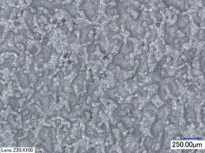
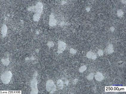
0
sive media that can be problematic in specific applications due to the possible introduction of inclusions into the sample’s surface and the risk of extra rounding on edges, delicate features, and corners.
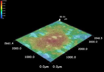
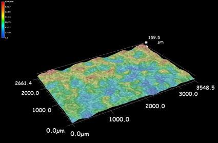
Fig. 3 shows the surface texture optimisation progression for PBF-EB Ti-6Al-4V specimens through the surface finishing operations. The as-built components showed typical surface texture features (Ra = 28 +
1 μm) that were eliminated through the CP process by removing 350 μm from the surface. The CP process reached a plateau and no significant change was observed upon further processing. At that point, the specimens were processed by CMP to achieve the required planarisation to target the required Ra. For the HCF (high-cycle fatigue) specimens built with contour and without contour, the Ra target was below 0.1 μm and
Metal Additive Manufacturing | Winter 2022 153 Vol. 8 No. 4 © 2022 Inovar Communications Ltd | contents | news | events | advertisers | print sub | e-newsletter | GETPDF
Fig. 3 Microscope images at 100 X magnification (a and b) with their 3D representations (c and d) of the surface of PBF-EB Ti-6Al-4V as-built tensile specimens, and the final surface after surface finishing (b and d). Average surface roughness (Ra) progression per surface material removal through the surface finishing operation (bottom). The blue area on the plot shows the CP progression and the red area shows the CMP progression [1]
Chemical polishing
Fig. 4 Average surface roughness (Ra) reduction per surface material removal through the surface finishing operation of PBF-LB GRCop-42, first CP followed by CMP (a). The blue area on the plot shows the CP progression, and the red area shows the CMP progression [1]
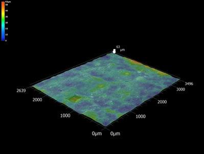
Ra = 0.07 + 0.02 μm for the contour specimens and Ra = 0.06 + 0.01 μm for the specimens without contour were obtained with the same SMR of 487 μm. Both samples showed the same surface material rates and level of planarisation. Some random porosity was observed in both samples, even though they were HIPed, probably due to small spots lacking fusion, but these were sporadic.
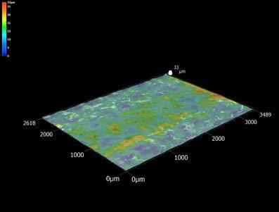
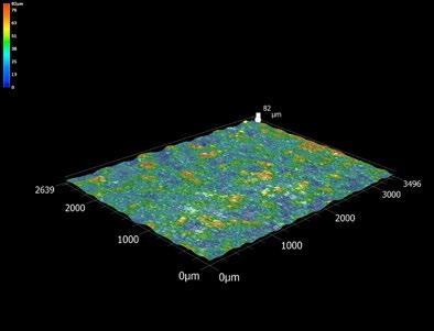
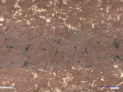
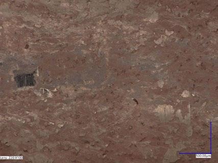
High-cycle fatigue testing was carried out on the PBF-EB Ti-6Al-4V specimens to study the difference between samples with and without
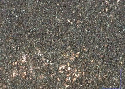
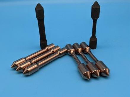
a contour. The results showed that, at 275 MPa, both sets of specimens were stopped with no failure at 1,728,000 cycles, but, for the specimens run at 600 MPa, there was a significant difference in the cycles to failure between the contour specimens (Nf = 22,000 + 9,000 cycles) and the specimens without contour (Nf = 6,000 + 2,000 cycles). This demonstrated the importance of the contour process, where the contour specimens showed a higher fatigue lifetime, even though the contour layer served as a sacrificial layer during the 487 μm material removal.
The second case study focussed on PBF-LB GRCop-42 (Cu-4%Cr-2%Nb). GRCop-42 is a high-strength, dispersion-strengthened copper alloy with excellent conductivity, currently used in liquid rocket engines by NASA and other commercial space companies. Fig. 4 shows the surface texture progression for typical non-HIPed specimens of this alloy through the surface finishing operations. The as-built components show surface texture features overtaken by the partially sintered/melted powder on the surface, with Ra = (18 + 2)
Metal Additive Manufacturing | Winter 2022 154 © 2022 Inovar Communications Ltd Vol. 8 No. 4 | contents | news | events | advertisers | print sub | e-newsletter |
0 5 10 15 20 25 0 100 200 300 400 500 600 Ra (µm) SMR
(µm)
World PM2022: corrosion and wear resistance
a) b) Ra = (18±2) µm SMR = As-built Ra = (4.3±0.4) µm SMR = (215±2) µm Ra = (0.61±0.04) µm SMR = (575±7) µm Initial CP +CMP
Chemical polishing Chemical mechanical polishing
World
PM2022: corrosion and wear
μm. The initial surface texture improved remarkably through the CP process; in this specific example, by removing around 200 μm from the surface, a Ra reduction of up to 78% was achieved; followed by the CMP process, reaching the lower possible Ra, where values under 0.6 μm were achieved (Fig. 4).
Stress (MPa)
890
UTS
0.2% YS
885
Stress (MPa)
885
880
880
875
875
870
870
865
865
860
860
855
855
850
890 Non-HIP HIP
Stress (MPa)
Stress (MPa)
395
395
Stress (MPa)
Stress (MPa)
Non-HIP HIP
395
390
385
395
390
390
385
Finally, the PBF-LB IN625 case study was considered. The surface texture optimisation was performed by removing 400 μm from the surface by CP followed by 100 μm by CMP. The initial surface roughness of the as-built specimens was Ra = (8.3 + 0.5) μm and Ra = (7.5 + 0.2) for the HIPed samples. After applying CP + CMP, the final surface roughness was Ra = (1.1 + 0.6) μm for the nonHIPed samples and Ra = (0.07 + 0.01) μm for the HIPed samples. The non-HIPed sample surfaces showed significant shallow pits from the overall porosity, while the HIPed samples' surfaces were perfectly smooth.
UTS As-built Processed 365
390
385
380
375
385
380
380
375
375
370
380
375
370
As-built Processed 365
400 Non-HIP HIP
400 Non-HIP HIP
370
S-S Elongation (%)
80
70
60
0.2% YS As-built Processed 30
80
70
60
50
40
50
As-built Processed 30
90 S-S Elongation (%) 850
90 Non-HIP
40
Elongation
Elongation
400 Non-HIP HIP
370
365
400 Non-HIP HIP
Fig. 5 shows the results of mechanical testing experiments performed on PBF-LB IN625 specimens. The tensile and yield strengths of the specimens were significantly reduced upon HIPing. Nonetheless, the surface finishing process increased these for both non-HIPed and HIPed samples and, in the case of the HIPed samples, the strength lost on HIPing was recovered. However, upon surface finishing, a significant decrease in elongation was observed. The observed effects on the tensile properties can also be associated with the residual compressive stress imparted to the material upon surface finishing. On the other hand, the effects of HIPing and surface finishing on fatigue properties were extremely significant, showcasing the importance of combining surface finishing and HIPing. Surface finished non-HIPed samples did not show a significant improvement in fatigue. The same was the case for HIP samples with no surface finishing.
365
S-S Elongation (%)
S-S Elongation (%)
80
70
0.2% YS As-built Processed 30
80
70
60
50
60
50
40
0.2% YS As-built Processed 30
90 Non-HIP HIP
Cycles to failure (Nf) Thousands Processed
HCF As-built Processed HIP
90 Non-HIP HIP
40
Cycles to failure (Nf) Thousands
HCF As-built Processed
Elon HIP
As-built Processed 0 500 1,000 1,500 2,000 2,500 3,000 3,500 4,000 4,500 5,000 Non-HIP HIP
Fig. 5 Tensile strength (a), 0.2% yield strength (b), elongation (c), and uniaxial tensile high-cycle fatigue (Load at 434 MPa, room temperature, R = 0.1, and 60 Hz) of PBF-LB IN625 specimens before and after surface finishing and HIPing [1]
The second paper, presented by Hanna Nilsson Ahman and Pelle Mellin (Swerim AB, Sweden) and Clarence Wahman and Cecilia Persson (Uppsala University, Sweden), considered the influence of laser power on the corrosion behaviour of a Mg-Y-Nd-Zr alloy, processed by Laser Beam Powder Bed Fusion.
Magnesium and its alloys were first investigated for their possible use as biodegradable orthopaedic implants early in the 20 th century and the first biodegradable metal implant to obtain a CE certification was an orthopaedic screw produced from a powder-extruded Mg-Y-Nd-Zr alloy.
PBF-LB of magnesium alloys was first shown to be feasible in 2010. The possibility of additively manufactured complex structures of a Mg-Y-NdZr alloy was first demonstrated in 2016 and a thorough investigation of the microstructure was published
Metal Additive Manufacturing | Winter 2022 155 Vol. 8 No. 4 © 2022 Inovar Communications Ltd | contents | news | events | advertisers | print sub | e-newsletter | GETPDF
Influence of laser power on corrosion behaviour of PBF-LB Mg-Y-Nd-Zr alloy
UTS Processed
As-built Processed 0 500 1,000 1,500 2,000 2,500 3,000 3,500 4,000 4,500 5,000 Non-HIP HIP
resistance
a) b) c) d)
in 2019. Moreover, the mechanical properties have been shown to match those of the powder-extruded Mg-YNd-Zr alloys. However, for Mg-Y-Nd-Zr alloys processed by PBF-LB, corrosion rates of the bulk material remain too high, currently being around 2-3 mm/year, while a degradation rate of 0.5 mm/year is the currently recommended limit. Secondly, Mg alloys degrade with H 2 gas as one of the main corrosion products. The amount of H 2 gas formed needs to be controlled, as too high a gas evolution can have an adverse effect on bone remodelling. A limit of an average H 2 gas evolution rate of 0.01 ml/cm 2 per day has been suggested.
In order to tackle the problem of the excessive corrosion rates of Mg-YNd-Zr alloys processed by PBF-LB, a greater understanding of the influence of the process parameters on
corrosion properties is needed. The authors believe that there have been no studies to date on the influence of the individual process parameters on the corrosion properties. Therefore, the aim of the reported study was to investigate one of the most important parameters, namely the influence of laser power on the corrosion rate.
A gas atomised Mg-Y3.9wt.%Nd3.0wt.%-Zr0.49wt.% alloy metal powder with a particle size range of 25-64 μm was processed by PBF-LB with a constant flow of argon running across the build bed. The oxygen content in the build chamber was kept below 0.1 %. For the production of the samples, the process parameters kept constant included a layer thickness (d) of 20 μm, a laser speed (v) of 1100 mm/s and a hatch distance (h) of 40 μm. The scanning direction was rotated by 67° between
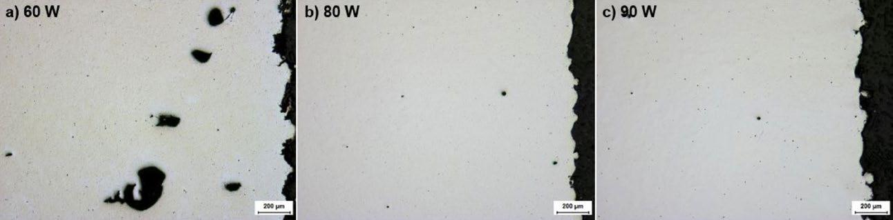
each layer. The laser power was varied between 60 W, 80 W and 90 W. Cylindrical samples, measuring 10 mm high and with a diameter of 5 mm, were additively manufactured.
Five samples from each sample group were additively manufactured and cut from the build using dry cutting to avoid the as-built surfaces being exposed to any reactions with cutting fluid. A cutting speed of 20 mm/s was applied using medium forces, and the sample was oscillated during cutting to minimise heating of the samples. The samples were then washed in an ultrasonic bath for 10 min immersed in ethanol.
An image of a representative additively manufactured cylindrical sample exhibiting the as-built surface after the ultrasonic bath washing is shown in Fig. 6 a). The results for the surface roughness analyses of the as-built surfaces of the three sample groups are presented in Fig. 6 b). The results show that a higher surface roughness was obtained for the samples produced with 60 W laser power, followed by the 80 W and finally 90 W. This shows that a lower laser power results in a higher surface roughness. In previous studies on other alloys processed by PBF-LB, it was observed that the surface roughness of the top surface can either decrease or increase with increasing laser power, depending on the other process parameters. Incomplete melting of powder is a plausible reason for the difference in surface roughness observed in this study.
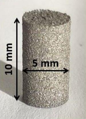
Metal Additive Manufacturing | Winter 2022 156 © 2022 Inovar Communications Ltd Vol. 8 No. 4 | contents | news | events | advertisers | print sub | e-newsletter |
60W 80W 90W Sa 0 5 10 15 20 25 a) a) 60 W b) 80 W c) 90 W b)
200 µm 200 µm 200
World PM2022: corrosion and wear resistance
Fig. 6 Average results from the measurements of the surface roughness, Sa, of the as-built cylinders [2] Fig. 7 Optical micrographs of the cross-sections of the samples, with the samples additively manufactured with 60, 80 and 90 W laser power [2]
µm
b)
Larger agglomerates of secondary phases
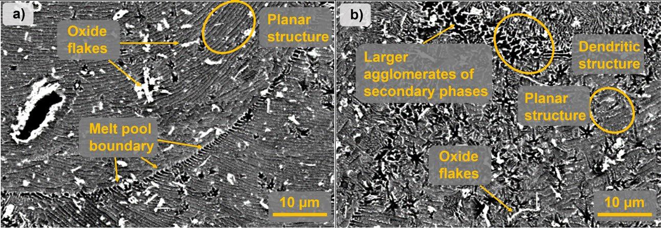
Melt pool boundary
Optical micrographs of the crosssections of the edges of samples are shown in Fig. 7. In the image of the sample produced with 60 W power, large internal pores are visible throughout the bulk of the material (Fig. 7 a). These large pores appear to be due to a lack of fusion (i.e., not enough energy is put into the material to melt it completely), the same effect causing the higher surface roughness. No significant difference can be observed between the samples produced with 80 W and 90 W power (Figs. 7 b and c respectively). The images of both samples show some small circular pores in the bulk of the material, measuring around 10 μm or below. These types of pores generally occur either through a key-hole effect related
to an unstable melt pool, or they could come from pores present in the powder. In this instance, either source is a possibility, as there were pores present in the powder and the magnesium is generally an unstable material. Moreover, the higher surface roughness of the 60 W sample, as measured by confocal microscopy, is also visible in these images, while no discernable differences can be seen for the 80 W and 90 W samples.
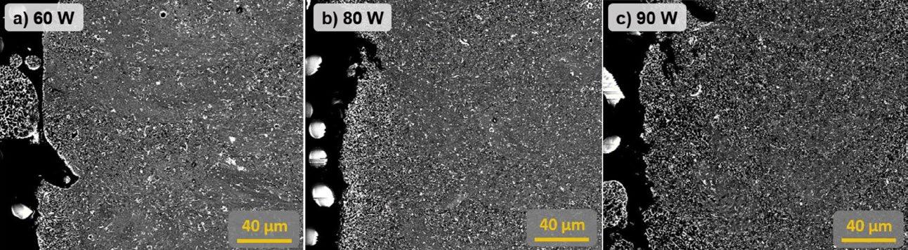
The SEM images of the edges of the cross-sections of the samples are shown in Figs. 8 and 9. Representative images of two regions with different microstructures seen in the samples can be observed at a high magnification in Figs. 8a and b. The first is presented in Fig.
8a, where the melt pool structures observed in previous studies of Mg-YNd-Zr alloys processed by PBF-LB are clearly distinguishable. This includes the clearly distinguishable melt pool boundary, as well as the planar structure within the melt pool. Around the edges of the cells, there are phases that appear brighter in the SEM images, which, in previous studies, have been shown to be Mg-rare earth intermetallic phases (RE = Y and Nd). The oxide flakes dispersed throughout the microstructure have also been noted in previous studies, which have shown that this type of structure usually corresponds to larger grains with a strong basal structure. In Fig. 8b, two other features of the microstructure can be detected. Firstly, there are
Metal Additive Manufacturing | Winter 2022 157 Vol. 8 No. 4 © 2022 Inovar Communications Ltd | contents | news | events | advertisers | print sub | e-newsletter | GETPDF
a)
Oxide flakes
Oxide flakes
Planar structure
Planar structure
Dendritic structure
10 µm 10 µm
Fig. 8 SEM images of the two types of microstructure observed at a high magnification: a) shows the oxide flakes, the melt pool boundaries and a cellular structure within the melt pool; b) shows the starlike shapes and a random network of secondary phases, corresponding to a dendritic structure [2]
a) 60 W b) 80 W c) 90 W 40 µm 40 µm 40 µm World PM2022: corrosion and wear resistance
Fig. 9 SEM images of the cross-sections of the samples, with the samples additively manufactured with 60, 80 and 90 W laser power [2]
Fig. 10 The results plotted from the hydrogen evolution tests [2]
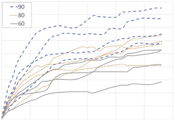
star like formations and, secondly, there are more randomly organised Mg-RE intermetallics, corresponding to a dendritic structure. This type of region has previously been shown to contain smaller equiaxed dendritic grains with sizes in the range of a few μm. The secondary phases in the form of Mg-Re intermetallics also appear in larger agglomerates in Fig. 8b in comparison with Fig. 8a. Comparing the microstructures along the edges of the three samples, representative of the three groups, in the SEM images of Fig. 9, it can be seen that the sample produced with a laser power of 60 W mainly exhibits the microstructural features of Fig. 8a, while, for the samples
produced with 80 W and 90 W power (Fig. 9 b and c), the microstructural features highlighted in Fig. 8b are more prevalent. These features are also visible in some regions along the edges of the sample produced with 60 W, but not to the same extent. Comparing the samples produced with 80 W and 90 W power, the structure highlighted in Fig. 8b appears to be more dominant in the 90 W sample than in the 80 W sample. In the bulk of the material, it is the microstructure presented in Fig. 8a that is the most prevalent for all samples.
The reason for these differences in microstructure between the samples has not been fully established by the authors. However, the
higher laser power contributes with two effects. The first is the higher volumetric energy input. As the difference between the melting point (Tm = 650°C) and the boiling point (Tb = 1050 °C) is very narrow for Mg, and the vapour pressure is also very high, Mg evaporation is observed for all samples during Additive Manufacturing. However, a higher amount of evaporation product is generally observed for the higher energy densities. This would lead to a greater shift in the alloying content, causing the precipitation of higher amounts of intermetallic particles.
A second effect of higher laser power is the difference in width and depth of the melt pool and this means a larger heat affected zone. The material is remelted and reheated more times, which could cause the precipitation and growth of secondary phases. The higher energy input also affects the thermal conditions in the material during Additive Manufacturing and can thus affect which types of microstructures are formed. The formation of equiaxed dendritic grains usually implies a homogeneous nucleation and growth, which usually takes place at slower cooling rates where there is time for segregation of elements. This would explain the higher presence of this type of structure along the edges of the additively manufactured pieces, where there is contact with the unmelted powder, as the unmelted powder has a much lower heat conducting capacity than the bulk. This would also explain the larger amount of the type of structure being present in the sample printed with a higher laser power.
The corrosion properties of the as-built surfaces were investigated using a Phosphate Buffered Saline solution as the corrosion medium. All corrosion measurements were carried out at 37°C to mimic biological conditions in the body. The corrosion rate was characterised by the hydrogen evolution rate, measured using a volumetric set up.
The results from the hydrogen evolution tests are presented in Fig. 10 and show that the samples additively manufactured with a laser
Metal Additive Manufacturing | Winter 2022 158 © 2022 Inovar Communications Ltd Vol. 8 No. 4 | contents | news | events | advertisers | print sub | e-newsletter |
18 16 14 12 10 8 0 5 90 80 60 10 15 Time
H 2 evolution (ml/cm 2 ) 20 25 30 6 4 2 0 World PM2022: corrosion and wear resistance
“The formation of equiaxed dendritic grains usually implies a homogeneous nucleation and growth, which usually takes place at slower cooling rates where there is time for segregation of elements.”
(days)
Alloy Fe Mo Ni V Mn Cr Si C 0xygen
Ancorwear 500 Remainder 0.61 0.70 - 1.39 0.66 0.50 0.17 0.02
Ancorwear 600 Remainder 0.37 4.14 - 0.60 1.31 0.21 0.44 0.03
Ancorwear SPL Remainder 1.48 0.09 0.14 1.01 0.08 1.23 0.23 0.03
Ancorwear S7 Remainder 1.57 - 0.30 0.78 3.15 0.69 0.51 0.03
Ancorwear SS Remainder 0.22 1.05 - 0.14 11.85 0.88 0.02 0.25
Table 1 Overview of alloy compositions evaluated in the study [3]
power of 90 W have the highest hydrogen evolution rate, followed by the 80 W and finally the 60 W. This was unexpected, as the samples produced with 60 W had both the highest surface roughness and the largest internal pores, as well as the highest number of pores.
The reason for the 60 W power samples exhibiting the lowest corrosion rate could be related to the size and amount of the secondary Mg-RE phases observed in the SEM images. The increase of Mg-RE intermetallic phases has previously been shown to have a detrimental effect on the corrosion properties of Mg alloys, because the Mg-RE phase has a higher corrosion potential than the Mg matrix. In aqueous solutions, the intermetallic phases work as local cathodes and give rise to an increased micro-galvanic corrosion.
These results indicate that, to a certain extent, the size and distribution of the secondary phases are more important than the surface roughness and internal porosity, at least when looking at the corrosion rate over twenty-eight days. Nevertheless, both surface roughness and pores are known to have an important adverse effect on the mechanical properties of materials processed by PBF-LB in general and for Mg alloys specifically. The effect of surface roughness on mechanical properties can be mitigated by various surface treatments such as chemical polishing. The internal pores of the samples produced at 60 W power, however, may have to be decreased to ensure sufficiently high mechanical properties.
Thus, the authors have proposed that future studies should include optimisation of the microstructure near the surfaces through the development of optimised PBF-LB process parameters of contours. Moreover, further focus should be put on understanding the effect of the main PBF-LB process parameters on the formation of the two types of microstructures observed in this study.
Development of wear resistant alloys for PBF-LB
The final paper in the session turned to the issue of wear resistance of PBF-LB materials. Corina Junghetu (Hoeganaes Corporation Europe, Romania) and Chris Schade and Tom Murphy (Hoeganaes Corporation, USA) highlighted the company’s development of a suite of wear resistant alloys for use in Laser Beam Powder Bed Fusion.
In general, hard materials for tooling and wear resistant applica -
tions are very difficult to machine, with the most common forming method being grinding. Utilising a grinding operation severely limits the shape of the final product. Additive Manufacturing, and PBF-LB in particular, allows intricate shapes to be formed for most alloy materials and enables low-cost prototyping of small wear-resistant components. These prototypes can be placed in service to collect data on the performance of both the material and design of the part. This can be done without incurring large costs due to moulds or machining of very hard materials. The design features of AM lend themselves to creating parts that could not be produced simply by grinding the shape from a block of metal. Therefore, there is great potential in utilising AM for producing serial parts for industrial use.
The reported study documented and introduced a new family of alloys called Ancorwear. These materials were designed specifically for PBF-LB and cover a hardness range
Metal Additive Manufacturing | Winter 2022 159 Vol. 8 No. 4 © 2022 Inovar Communications Ltd | contents | news | events | advertisers | print sub | e-newsletter | GETPDF
“... both surface roughness and pores are known to have an important adverse effect on the mechanical properties of materials processed by PBF-LB in general and for Mg alloys specifically.”
World PM2022: corrosion and wear resistance
Alloy Tempering Temp. °C UTS (MPa) YS (MPa)
Elongation (%) HRC
Ancorwear 500 538 993 903 18.1 21
Ancorwear 600 538 1469 1255 12.5 49
Ancorwear SPL 538 1482 1269 13.1 45
Ancorwear S7 538 1269 876 2.8 52
Ancorwear SS 538 896 662 8.7 38
Table 2 Mechanical properties of PBF-LB samples after tempering [3]
that mimics wrought alloys available for wear resistant applications. The mechanical properties of these alloys, as well as case studies and wear testing, have been reviewed to demonstrate applicability to real world applications.
Several alloys have been developed, covering a range of hardness and ultimate tensile strength values. There are a number of factors to be considered when choosing an appropriate alloy for an application. These can include: the structural properties, operating temperature, atmosphere or corrosion resistance and toughness. The main starting point for these attributes is the chemical composition of the alloys, as shown in Table 1. Ancorwear 500 and 600 are alloys made to mimic conventional wrought, abrasion-resistant grades commonly produced in plate steels. These grades of steel are typically difficult to form and are used in fairly simple shapes. Ancorwear SPL is a chromium/nickel-free alloy similar to the 500 and 600 grades but is designed to meet health and
safety requirements where chromium and nickel are not permitted. S7 is a typical tool steel, but has the advantage of good impact and shock resistance; also, it has good resistance to softening at moderately high temperatures with an excellent combination of high strength and toughness. Ancorwear SS is a stainless steel that has high hardness, but provides abrasion resistance when moderate corrosion resistance is also needed.
All powders used in this study were produced by gas atomisation, with the exception of Ancorwear SS, which was produced by water atomisation. All powders were screened to a nominal 15-53 μm particle size range, which is common for PBF-LB processing. Specimens for the study were processed by melting powder layer by layer with an Yb fibre laser (400 W) within an argon-filled chamber. Cubic samples (10 x 10 x 10 mm) were built with a variety of different settings to evaluate the porosity content produced for all the alloys listed in Table 1. A constant
layer thickness was used for all samples, while the laser power, hatch distance and scanning speed were varied. Image analysis was used to measure the porosity content of the cross-section of the cubes perpendicular to the build direction. Settings for additively manufactured mechanical test specimens were chosen for all the alloys that led to a density of greater than 99%.
A set of standard settings was used to build dogbone tensile test specimens. Samples were cut from the build plate in the as-built condition after production. Tensile specimens were tempered for 1 h at 538°C in a nitrogen atmosphere prior to testing on all the grades except Ancorwear SS. This material was first heated to 1260°C for 30 min in nitrogen atmosphere and furnace cooled to room temperature. This heat treatment formed a dual phase microstructure of martensite and ferrite. Following the initial heat treatment at 1260°C, the Ancorwear SS was tempered at 538°C for 1 h in nitrogen to temper the martensite that was formed.
To determine the maximum hardness achievable in each alloy, tempering studies were performed on all materials. Due to the high level of residual stresses from the PBF-LB process and the nature of the alloys (high hardness), it was recommended that these materials should not be used in the as-built state. Tempering was performed at temperatures ranging from 300-760°C for 1 h in a nitrogen atmosphere. For each alloy, the tempering temperature, which achieved maximum hardness, is shown in Table 2. As expected, the S7 tool steel material has the highest hardness and lowest ductility. The Ancorwear 500, which is a hardenable low-alloy steel, but with a carbon content which lends itself to welding, has the lowest hardness but highest elongation, indicating a good toughness. The Ancorwear 600, which is more highly alloyed (nickel), including a higher level of carbon, has a hardness close to that of S7, but with a much higher level of ductility. The SPL, which has no nickel or chromium
Metal Additive Manufacturing | Winter 2022 160 © 2022 Inovar Communications Ltd Vol. 8 No. 4 | contents | news | events | advertisers | print sub | e-newsletter |
World PM2022: corrosion and wear resistance
“Due to the high level of residual stresses from the PBF-LB process and the nature of the alloys (high hardness), it was recommended that these materials should not be used in the as-built state.”
and a low level of carbon, has both high hardness and good ductility. The Ancorwear SS, which has low carbon (typical of stainless steels), has a HRC of 38, which is very high for a non-carbon stainless steel. The low carbon allows for a better corrosion resistance of this alloy compared to the other materials.
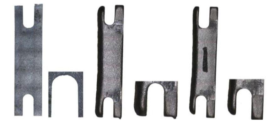
The microstructures of alloys 500, 600, SPL, and S7 were tempered martensite with varying concentrations of fine precipitated carbides in ferrite. The chemical compositions of each alloy, as shown in Table 1, control the size, composition, and concentration of the carbides, with the higher carbon contents resulting in a higher carbide population density compared with the lower carbon contents. In addition, the ferritic regions were larger and more distinct in the lower carbon samples.
The fifth alloy, Ancorwear SS, had a dual phase stainless steel composition. Mechanical and physical properties of this alloy type were developed by heating the as-built sample in the two-phase region of the phase diagram (ferrite and austenite) then cooling to transform the austenite to martensite. The martensite was tempered at 538°C before mechanical testing.
The alloys shown in Table 1 exhibit a range of hardness that could be used in a variety of applications. The initial case study presented related to the hammers and screens in a hammer mill for grinding materials. In order to investigate the use of PBF-LB, both the hammers and screens were additively manufacture from materials shown in Table 1, grinding trials were performed, and wear and lifetime of the AM parts were quantified. The material that was chosen to be ground was a metal alloy consisting of titaniumiron-manganese with a hardness of HV30 = 355.
For the field trials, Ancorwear SPL was chosen due to its high hardness but good toughness (as indicated by its elongation values). Since the hammers rotate at a high RPM, they need to have good impact toughness so that do not fail cata -
strophically. If a hammer were to shatter when operating at >3000 RPM, significant damage to the mill could occur. In addition to the hammers, the perforated screens were also additively manufactured via PBF-LB. Typically, because these screens are conventionally formed by rolling, the material cannot have a high hardness, as this would make forming difficult. However, since PBF-LB can produce the curved screen, a higher strength/hardness material was considered as a potential improvement. In order to have a direct comparison with the standard hammers and screens, an equal number of hammers and screens manufactured from both the standard process (machining and rolling) and PBF-LB were put in the hammer mill at equivalent positions. The wear and damage to each of the
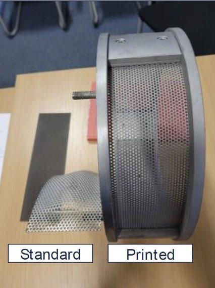
parts were monitored as a function of the amount of metal alloy that was ground.
Fig. 11 shows photographs of the hammers and screens. In the case of the screens, the process was stopped after grinding 470 kg of the metal alloy; the photograph on the left shows that the perforated hole diameter was much larger with the standard screen material when compared to the SPL material processed by PBF-LB. The right picture of the screens showed that the standard processed screens failed at 1153 kg of ground material, while the screen produced via PBF-LB was still serviceable. All hammers lasted the lifetime of the campaign and the weights were measured before and after the grinding campaign to gain an indication of the weight loss. The wear on
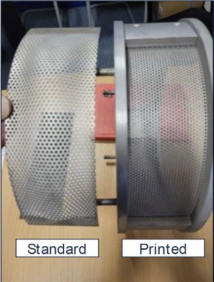
Metal Additive Manufacturing | Winter 2022 161 Vol. 8 No. 4 © 2022 Inovar Communications Ltd | contents | news | events | advertisers | print sub | e-newsletter | GETPDF
Fig. 11 Hammers and screens produced conventionally and by AM [3]
Standard
Hammer as new Used machined Used additively manufactured
Standard AM AM
World PM2022: corrosion and wear resistance
20 µm 20 µm World PM2022: corrosion
40 µm 40 µm
Fig. 12 Microstructures of the two alloys in the core of the hammer (left) and at the wear surface of the hammer (right). Top is the standard machined alloy and bottom is Ancorwear SPL [3]
the standard material was 19.4%, while the PBF-LB SPL alloy exhibited a weight loss of 25%. This difference in wear was not unexpected, as the hardness of the standard material was 49 HRC versus a hardness of 46 HRC for the Ancorwear SPL. Since the performance of the PBF-LB SPL was unknown, a conservative approach had been taken to have a more ductile material (lower hardness) in order to avoid catastrophic failure on the initial trials. While the wear rate of the SPL was higher, there were no
catastrophic failures and there are further improvements in the heat treatments that can be undertaken to improve the hardness of the SPL.
A comparison of the two hammer microstructures is shown in Fig. 12. The upper two images are taken from the standard machined alloy hammer and the lower two from the SPL alloy hammer. In each pair of images, the left is from the core, while the wear surface is depicted in the right image. The core microstructures (left images) are substantially different.
In the standard alloy, details of the well-defined lath martensite are clearly visible and are typical of a tempered low-carbon martensite. A representative area from the SPL alloy core shows evidence of a heavily tempered lath martensite, with large ferritic regions populated with a distribution of small carbides. This difference in microstructure accounts for the hardness disparity and was probably caused by the thermal history of the AM part. As stated earlier, the AM part was tempered at the conclusion of the build process at a temperature designed to attain the maximum hardness, but still have ductility to resist the impact. In building the hammer, as opposed to the substantially smaller tensile bar, the temperature within the part remains elevated for a longer time, due to the repetitive heating from the laser. Consequently, the part undergoes both a microstructural transformation during cooling from the melt and what may be considered a self-tempering as the part is continually reheated during the remainder of the build. Finally, at the conclusion of the build cycle, the hammer is tempered again at the predetermined temperature, which further tempers the already tempered microstructure.
40 µm 40 µm
In the two wear surface images (Fig. 12, right), the white coating on the left side of each image is the built-up edge of the metal alloy powder on the hammer edge and the right side of each image is typical of the core, although at a lower magnification compared with the two core-only images. The microstructure differences are apparent, as is distortion to the microstructure in the form of flow of material from particle impact at the hammer edge during grinding. It is evident in these images that the flow and distortion in the AM hammer is at a greater depth compared with the machined hammer, which may help account for more material being eroded from the surface during use, thus contributing to a greater weight loss.
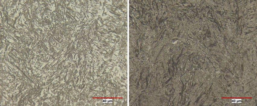
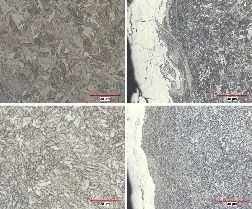
Metal Additive Manufacturing | Winter 2022 162 © 2022 Inovar Communications Ltd Vol. 8 No. 4 | contents | news | events | advertisers | print sub | e-newsletter |
Fig. 13 Microstructures of Ancorwear 600 as built (left) and tempered at 315°C (right) [3]
and wear resistance
World PM2022: corrosion and wear resistance
Based on the knowledge gained from this initial pilot trial and the finding that the AM material already undergoes self-tempering from repetitive scanning of the laser over the prior built layer, it was concluded that a more appropriate material selection for this application might have been Ancorwear 600. Fig. 13 shows the microstructure of Ancorwear 600 in the as-built condition and tempered at 315°C for 1 h. It is clear that the microstructure in both conditions is martensitic and more closely resembles the microstructure of the standard alloy. The Ancorwear 600 alloy has higher carbon than the other materials and, therefore, the hardenability of the alloy is greater and the hardness of the martensite that is formed is also greater when compared to the other alloys. The primary purpose of tempering is to impart toughness to the alloy. This occurs due to the relief of internal stresses caused by the formation of martensite and the precipitation and spheroidisation of carbides. Alloying elements have a direct effect on the latter. Elements such as manganese, nickel, and silicon have only a small effect, since they do not form carbides. Elements such as chromium, molybdenum and vanadium are known to enhance hardness at higher tempering temperatures by forming alloy carbides. The effectiveness of these elements depends on their solubility in austenite and the nature of the carbide formed. These alloying elements also retard the coalescence of carbides, leading to temper resistance. Nickel has a synergistic effect on the hardenability when added with chromium and molybdenum and is known to increase impact toughness for alloys with a martensitic microstructure.
On comparing the mechanical properties of Ancorwear 600 and Ancorwear SPL, the ductility of the two materials is similar, while the hardness of the 600 alloy is greater. This, combined with the fact that the microstructure resists the tempering from the PBF-LB process, leads to a harder, more wear-resistant alloy that should also resist the impact
seen in the performance of the grinding hammers.
Prior to running additional case studies with the Ancorwear 600, Charpy impact testing will be performed to ensure that the material will not fail catastrophically. In addition, wear tests, such as pin and disc, will be performed to correlate the wear rate test results and mechanisms (by metallography) with the actual operation of the hammers in the mill.
Author and contacts
Dr David Whittaker
Tel: +44 1902 338498 whittakerd4@gmail.com
[1] Agustin Diaz, REM Surface Engineering, USA adiaz@remchem.com
[2] Hanna Nilsson Åhman, Swerim AB, Sweden / Division of Biomedical Engineering, Dept of Material Science and Engineering, Uppsala University, Sweden hanna.nilsson-ahman@swerim.se
[3] Corina Junghetu, Hoeganaes Corporation Europe, Romania corina.junghetu@hoeganaes.com
References
[1] 'Surface Texture Optimization Of Metal Additive Manufactured Components Through Chemical-Mechanical Polishing To Improve Mechanical And Corrosion Resistance Performance,' Diaz, A, et al. As presented at the WorldPM 2022 Congress, October 9–13, 2022, and published in the proceedings by the European Powder Metallurgy Association (EPMA).
[2] ' Influence Of Laser Power On The Corrosion Behavior Of A Mg-Y-NdZr Alloy Produced By Powder Bed Fusion - Laser Beam,' Nilsson Åhman, et al. As presented at the WorldPM 2022 Congress, October 9–13, 2022, and published in the proceedings by the European Powder Metallurgy Association (EPMA).
[3] 'Development of Wear Resistant Alloys for Use in Laser Powder Bed Fusion,' Junghetu, C, et al. As presented at the WorldPM 2022 Congress, October 9–13, 2022, and published in the proceedings by the European Powder Metallurgy Association (EPMA).
Euro PM2023
The Euro PM2023 Congress & Exhibition, organised and sponsored by the European Powder Metallurgy Association, will be taking place in Lisbon, Portugal, October 1–4, 2023. www.europm2023.com
Metal Additive Manufacturing | Winter 2022 163 Vol. 8 No. 4 © 2022 Inovar Communications Ltd | contents | news | events | advertisers | print sub | e-newsletter | GETPDF
Industry events
Metal AM magazine is dedicated to driving awareness and development of metal Additive Manufacturing and its related technologies. Key to this aim is our support of a range of international partner conferences and exhibitions. View our complete events listing on www.metal-am.com

2023
Military Additive Manufacturing Summit
February 1–2, Tampa, FL, USA www.militaryam.com
Additive Manufacturing Strategies 2023
February 7–9, New York, NY, USA www.additivemanufacturingstrategies.com


MIM2023
Fraunhofer Direct Digital Manufacturing Conference (DDMC) 2023 March 15–16, Berlin, Germany www.ddmc-fraunhofer.de
AMUG 2023 March 19–23, Chicago, IL, USA www.amug.com
EBAM 2023 – International Conference on Electron Beam Additive Manufacturing March 22–24, Erlangen, Germany www.ebam.fau.de
Hannover Messe 2023 April 17–21, Hannover, Germany www.hannovermesse.de
RAPID + TCT May 2–4, Chicago, IL, USA www.rapid3devent.com
Space Tech Expo USA 2023 May 2–4, Long Beach, CA, USA www.spacetechexpo.com
Metal Additive Manufacturing | Winter 2022 164 © 2022 Inovar Communications Ltd Vol. 8 No. 4 | contents | news | events | advertisers | print sub | e-newsletter |
Events guide
February 27–March 1, Costa Mesa, CA, USA www.mim2023.org Download our app for Apple and Android devices...
PM China 2023 / AM China 2023
May 31–June 2, Shanghai, China en.pmexchina.com
TCT 3Sixty June 7–8, Birmingham, UK www.tct3sixty.com
World Titanium Conference 2023 (Ti-2023)
June 12–16, Edinburgh, Scotland www.iom3.org/events-awards/world-titaniumconference-2023.html
PowderMet2023 / AMPM2023
June 18–21, Las Vegas, NV, USA www.powdermet2023.org / www.ampm2023.org
MAPP Second International Conference June 28–29, Sheffield, UK www.mapp.ac.uk/events/mapp-2nd-internationalconference
AM Forum Berlin July 4–5, Berlin, Germany www.am-forum.eu
EPMA Powder Metallurgy Summer School July 17–21, Dresden, Germany www.summerschool.epma.com
EMO Hannover 2023 September 18–23, Hannover, Germany www.deutschemesse.co.uk/emo
Euro PM2023 October 1–4, Lisbon, Portugal www.europm2023.com
Formnext November 7–10, Frankfurt, Germany www.formnext.com
Space Tech Expo Europe 2023 November 14–16, Bremen, Germany www.spacetechexpo-europe.com

all our back issues for free!
2024
Metal Additive Manufacturing | Winter 2022 165 Vol. 8 No. 4 © 2022 Inovar Communications Ltd | contents | news | events | advertisers | print sub | e-newsletter | GETPDF Events guide
World PM2024 October 13–17, Yokohama, Japan www.worldpm2024.com and access
If you would like to see your Metal Additive Manufacturing related event listed in this magazine and on our websites, please contact Jo Sheffield: jo@inovar-communications.com
METAL AM
TO OUR NEWSLETTER SUBSCRIBE
The Metal Additive Manufacturing e-newsletter is sent to key metal AM industry professionals worldwide, twice a week. Register today to ensure you benefit from reading the latest industry news and advances in metal AM.
E-newsletter subscribers also benefit from a free digital subscription to Metal AM magazine. As soon as each new issue is available we’ll send you an email containing a direct link to your free digital copy.
www.metal-am.com/subscribe-tothe-metal-additive-manufacturing-enewsletter
www.metal-am.com

COMMUNICATIONS INOVAR
Advertisers’ index & buyer’s guide
Our advertisers’ index and buyer’s guide serves as a convenient guide to suppliers of AM machines, materials, part manufacturing services, software and associated production equipment. In the digital edition of Metal AM magazine, available at www.metal-am.com or via the Metal Additive Manufacturing app, simply click on a company name to view its advert, or on the weblink to go directly to its website.

AM MACHINES
Laser Beam Powder Bed Fusion (PBF-LB)
3D Systems, Inc. 06 www.3dsystems.com
Eplus3D 48 www.eplus3d.com
Farsoon Technologies 57 www.farsoon.com
GF Machining Solutions 21 www.gfmsadditive.com
Guangdong Hanbang 3D Tech Co., Ltd. 46 en.hb3dp.com
KOLIBRI Metals GmbH IBC kolibri.de.com
TRUMPF SE + Co. KG 35 www.trumpf.com
Binder Jetting (BJT)
Desktop Metal, Inc. OBC www.desktopmetal.com
Digital Metal 10 www.digitalmetal.tech
Material Extrusion (MEX)
Rapidia Tech Inc 24 www.rapidia.com
Hybrid AM
Matsuura Machinery Ltd 75 www.matsuura.de
Directed Energy Deposition (DED)
TRUMPF SE + Co. KG 35 www.trumpf.com
Metal Additive Manufacturing | Winter 2022 167 Vol. 8 No. 4 © 2022 Inovar Communications Ltd | contents | news | events | advertisers | print sub | e-newsletter | GETPDF Advertisers’ index / buyer’s guide
2. WEBSITE // go-to resource on all aspects of the metal Additive Manufacturing 37% EUROPE ASIA/ROW USAGE BY DEVICE DESKTOP 39% 61% DatabasedonNov2020 Oct2021 **DatabasedonDecember2021analysis ANNUAL TRAFFIC loads per month* Average Year on year 61,661 43,391 36% METAL AM 5-7 MAGAZINE: DIGITAL + PRINT // 8-9 WEBSITE // 14 CONTACT // // 2022 Media Pack The international media platform for the metal Additive Manufacturing 3D printing industry For more information contact Jon Craxford, Advertising Sales Director Tel: +44 207 1939 749
Wish you were here?
jon@inovar-communications.com
Alphabetical index
3D Systems, Inc. 6
Addiblast by FerroECOBlast 30
AM 4 AM s.à.r.l 44
AM China 134
AM Solutions - Rösler Group 15
AMUG 106
Blue Power Casting Systems GmbH 51 Bodycote 41
Burloak Technologies 42
Carbolite Gero Ltd 31
Centorr Vacuum Industries 72
CM Furnaces Inc. 28
CNPC Powder Group Co., Ltd. 27
DCM Tech Corporation 67
Desktop Metal, Inc. Outside back cover
Digital Metal 10
DSH Technologies 81
EDM Network Inc. 68
EDM Performance Accessories, Inc. 82
Elnik Systems 12
Eplus3D 48
EPSI 62
Equispheres 18
Euro PM2023 150
Extrude Hone Ltd 29
Farsoon Technologies 57 Formnext 86
Fraunhofer DDMC 2023 124
Gasbarre Products, Inc. 60
GF Machining Solutions 21
Gränges AB 65
Guangdong Hanbang 3D Tech Co., Ltd. 46
Hexagon Products Development Pvt Ltd. 69 Höganäs AB 39
Hunan Hualiu New Materials Co., Ltd. 52
IMR Metal Powders Technologies GmbH 47 Indo-MIM 79
Kennametal Inc. 54
KOLIBRI Metals GmbH Inside back cover
Kymera International 61
LÖMI GmbH 78
Material Technology Innovations Co., Ltd 71 more >>>
PRE & POST-PROCESSING TECHNOLOGY
Addiblast by FerroECOBlast 30 www.addiblast.com
AM Solutions - Rösler Group 15 www.solutions-for-am.com
DCM Tech Corporation 67 www.dcm-tech.com
EDM Network Inc. 68 www.edmnetwork.com
EDM Performance Accessories, Inc. 82 www.edmperformance.com
Extrude Hone Ltd 29 www.extrudehone.com
GF Machining Solutions 21 www.gfmsadditive.com
RENA Technologies Austria GmbH 63 www.rena.com
Rollwasch® Italiana S.p.a. 66 www.rollwasch.it
Solukon Maschinenbau GmbH 45 www.solukon.de
TOP Environmental Technology 59 www.iectop.com
PROCESS MONITORING & CALIBRATION
Atmosphere analysis
Process Sensing Technologies 73 www.processsensing.com
HIP SYSTEMS & SERVICES
Bodycote 41 www.bodycote.com
EPSI 62 www.epsi-highpressure.com
INSPECTION & CALIBRATION
ZEISS International 17 www.zeiss.com
Metal Additive Manufacturing | Winter 2022 168 © 2022 Inovar Communications Ltd Vol. 8 No. 4 | contents | news | events | advertisers | print sub | e-newsletter |
Advertisers’ index / buyer’s guide
HEAT TREATMENT & SINTERING
Sintering, debinding and heat treatment systems
Carbolite Gero Ltd 31 www.carbolite-gero.com
Centorr Vacuum Industries 72 www.vacuum-furnaces.com
CM Furnaces Inc. 28 www.cmfurnaces.com
Elnik Systems 12 www.elnik.com
Gasbarre Products, Inc. 60 www.gasbarre.com
LÖMI GmbH 78 www.loemi.com
TAV Vacuum Furnaces SPA 53 www.tav-vacuumfurnaces.com
Toll debinding & sintering
DSH Technologies 81 www.dshtech.com
Gas & gas generation
NEL Hydrogen 64 www.nelhydrogen.com
Matsuura Machinery Ltd 75
Metal Powder & Process Limited 20
Metalpine GmbH 16
MIM2023 115
NEL Hydrogen AS 64 Oerlikon AM 77
PM China 2023 123
PMAI 143
PowderMet2023 / AMPM2023 144
Praxair S.T. Technology, Inc Inside front cover Process Sensing Technologies 73
RAPID + TCT 98
Rapidia Tech Inc 24
RENA Technologies Austria GmbH 63 Rio Tinto 76
PART MANUFACTURERS
AM Solutions - Rösler Group 15 www.solutions-for-am.com
Burloak Technologies Inc. 42 www.burloaktech.com
Indo-MIM 79 www.indo-mim.com Kennametal Inc. 54 www.kennametal.com
KOLIBRI Metals GmbH IBC kolibri.de.com
Oerlikon AM 77 www.oerlikon.com
Sandvik Additive Manufacturing 23 www.additive.sandvik
Seurat Technologies 04 www.seuratech.com
Sintavia, LLC 36 www.sintavia.com
CONSULTING, TRAINING & MARKET DATA
DSH Technologies 81 www.dshtech.com
Wohlers Associates, Inc. 85 www.wohlersassociates.com
Rollwasch ® Italiana S.p.a. 66 S&S Scheftner GmbH 25
Sandvik Additive Manufacturing 23 Seurat Technologies 4 Sintavia, LLC 36
Solukon Maschinenbau GmbH 45
TAV Vacuum Furnaces SPA 53 Tekna 8
TOP Environmental Technology 59
TRUMPF SE + Co. KG 35
Ultra Fine Specialty Products 55
VDM Metals 33
Wohlers Associates 85 World PM2024 116
ZEISS International 17
Metal Additive Manufacturing | Winter 2022 169 Vol. 8 No. 4 © 2022 Inovar Communications Ltd | contents | news | events | advertisers | print sub | e-newsletter | GETPDF
Advertisers’ index / buyer’s guide
POWDERS, POWDER PRODUCTION AND ANALYSIS
Metal powders
AM 4 AM s.à.r.l 44 www.am-4-am.com
CNPC Powder Group Co., Ltd. 27 www.cnpcpowder.com
Equispheres 18 www.equispheres.com
Gränges AB 65 www.granges.com
Höganäs AB 39 www.hoganas.com
Hunan Hualiu New Materials Co., Ltd. 52 www.hlpowder.com
IMR Metal Powders Technologies GmbH 47 www.imr-metalle.com
Kennametal Inc. 54 www.kennametal.com
KOLIBRI Metals GmbH IBC kolibri.de.com
Kymera International 61 www.kymerainternational.com
Material Technology Innovations Co., Ltd. 71 www.mt-innov.com
Metalpine GmbH 16 www.metalpine.at
Oerlikon AM 77 www.oerlikon.com
Praxair S.T. Technology, Inc IFC www.praxairsurfacetechnologies.com
Rio Tinto 76 www.riotinto.com
S&S Scheftner GmbH 25 www.scheftner.dental
Sandvik Additive Manufacturing 23 www.additive.sandvik
Tekna 08 www.tekna.com
Ultra Fine Specialty Products 55 www.ultrafinepowder.com
VDM Metals 33 www.vdm-metals.com
Feedstock mixers
Hexagon Products Development Pvt Ltd. 69 www.alphiemixer.com
Atomisers
Blue Power Casting Systems GmbH 51 www.bluepower-casting.com
Metal Powder & Process Limited 20 www.metalpowderprocess.co.uk
Tekna 08 www.tekna.com
Powder processing, classification & analysis
Blue Power Casting Systems GmbH 51 www.bluepower-casting.com
EVENTS & COURSES
AM China 134 www.amatex.cn
AMUG 106 www.amug.com
Euro PM2023 150 www.europm2023.com
Formnext 86 www.formnext.com
Fraunhofer DDMC 2023 124 www.ddmc-fraunhofer.de
MIM2023 115 www.mim2023.org
PM China 2023 123 www.pmexchina.com
PMAI 143 www.pmai.in
PowderMet2023 / AMPM2023 144 www.powdermet2023.org / www.ampm2023.org
RAPID + TCT 98 www.rapid3devent.com
World PM2024 116 www.worldpm2024.com
Metal Additive Manufacturing | Winter 2022 170 © 2022 Inovar Communications Ltd Vol. 8 No. 4 | contents | news | events | advertisers | print sub | e-newsletter | Advertisers’ index / buyer’s guide
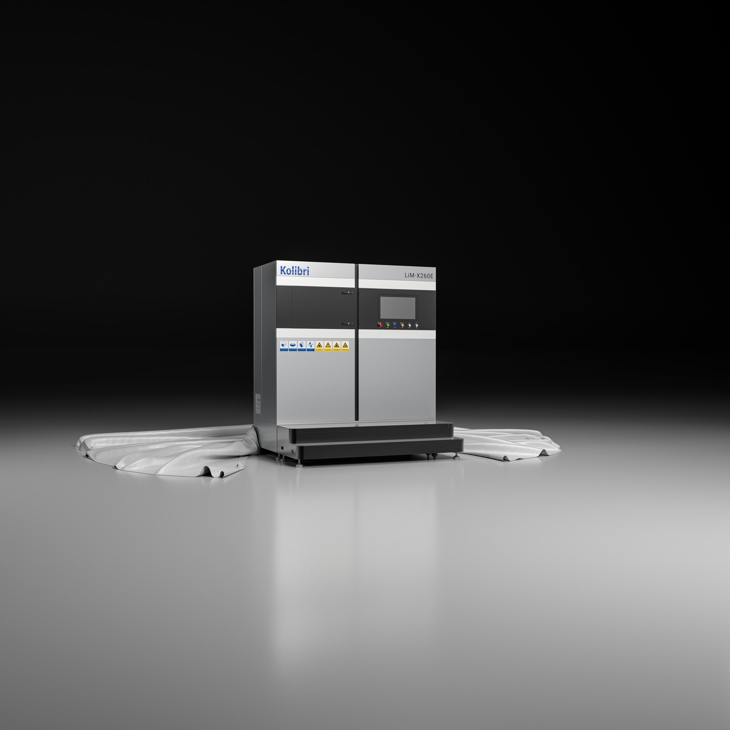
WHY is metal 3D printing always so costly? Kolibri Metals GmbH Hummelau 3 88279 Amtzell www.kolibri.de.com Machines for 3D Print Materials for SLM/ SLS Metal Matrix Composits Metallurgy Knowledge Maximum Simplicity LIM LASER Missed us on formnext fair? Visit us! Sorry, it's NOT... Quick machine installation Laser calibrating by yourself Intuitve service features Blue Man proof Competitive pricing
The Shop System™
Now offering an expanded lineup of the world’s best-selling metal binder jet machine
Shop System
The original plug-and-play solution from Desktop Metal to get started 3D printing metal parts fast - no prior binder jetting experience required
Everything you need at an affordable price. Intuitive software drives a complete system, from 3D printer and depowdering station to an industrial-grade furnace
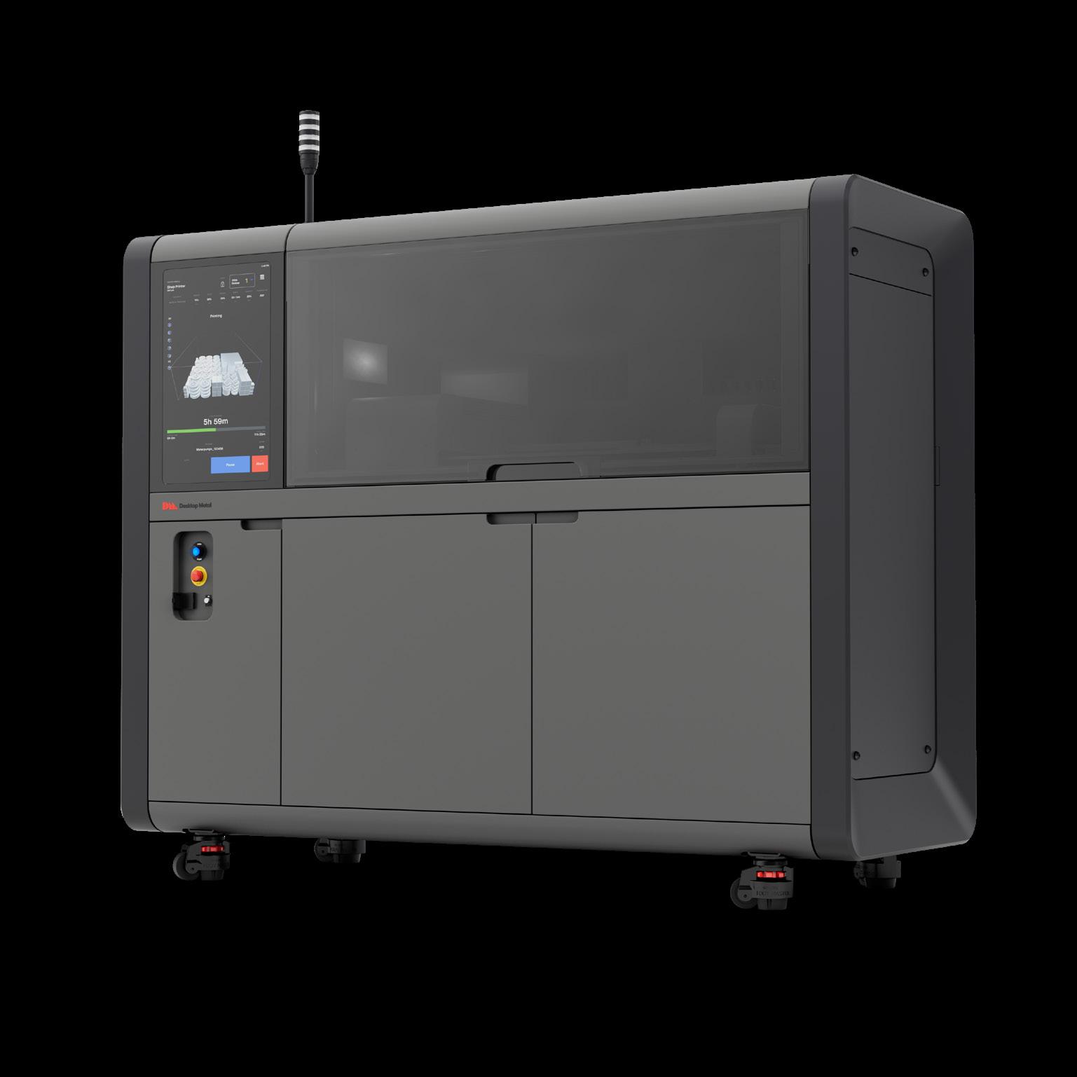
Shop System+
A more economic solution for high-power customers to reduce operating costs with locked in discounts on DM powder and binders
Lower the cost of additive operations and improve part costs to drive faster ROI with the same plug-and-play experience and materials as the base package
Shop System Pro
A more flexible solution for customers with powder metallurgy experience that unlocks custom printing and sintering process parameters
Expand beyond DM-supplied alloys to new applications or reduce operating costs through the use of third-party or proprietary powders
Learn more by downloading the Shop System specifications teamdm.com/ShopPackages NEW PACKAGES AVAILABLE
