Q2 v2 A'2
Q2 v2 A'2
A' v A'2 v2 v3 A3 v2 A'2 v3 2 2 v3 A–3 '2 v3 Kinetics S. Roy – U. K. Maity – A. K. Pramanick P. vK. of liquid metal flow in gating design of investment Acasting production 2 ADatta 3
=> PV = nMRCT [RU = MRC] [M = molecular weight] => RTvCaT3 =[nM vgT = m] [m=mass] P1V1PV =mmR and V =V ] 1 temperature 1 a [ m At ambient Ta, P1V1 = m11TRa 2 [P1 = Patm] P2V2 m2 RTm 2Tm At high temperature Tm, m RT PP21V12 = m TRT T 1=V2] P2 P112 2 amm 1aPgas[mP1P2and PV atm Pgas P2V2 m2 RT Q=vg. Ag 1Tma 2TTm P1V1 m1 RT a 1 a [ m and V1=VQ2] = v . A = C .v . A f f g D g g T P2V2 m2RT Tm P2 P1 2 m 2Pgas P1 P2 Patm Pgas 1Ta T P2 P1 2 m Pgas P1 P2 Patm Pgas 1Ta 2 P cos r (iii) Stefanescu’s approach for capillary mold: The resistance to flow through a channel of radius r, can be 2 P cos calculated r as [10]: 2γ 2 cosθ ∆P Pγ = − cos
Velocity at section -3: v3 A3 = v2 A'2 ∴ v3 = A'2 v2 v3 = vg
A3
Velocity at section -3 is known as gate velocity: v3 = vg Now, applying surface2 tension correction factor final velocity P v f [v g
will be, v f = [vg 2 −
∆Pγ
ρliq
]
]
liq Q=vg. Ag
.A Qf =g.vfA g = CD .vg. Ag Initial Discharge Rate [11]: Q=v g Corrected Discharge Rate: Qf = v f. Ag = CD .vg. Ag
Filling Time: t f =
Vm Qf
The velocity will be checked by Reynold’s No [12]. For liquid metal, flow will be considered as laminar flow, if, Re < 20000. Sprue design: For first part of Dam Sprue d z rr Aspiration correction, AS z Cu A1 z 0 ,, hence hence S 4 0 d z A z A z d z A z A z g Cu G Cu 2 1 hence Where γ is the surface energy between the , 4 21 Cu S 3 0 AS z Cu liquid z 0 and A1 metal dS z0 4 d z , hence A z A ' z Thus cup diameter d can be calculated. d AG D z S cu A 2 z 2 3 hence g D z 2 3 its vapor phase, and θ is the contactA angle between zS A0 the zmetal d Cu z1 , P 2 4 Cu 3 Cu 1 (2) v12 the v2mold. P v2 [v12 ] dD z3 AD zS A' 2 z3 and For first part of Dam Sprue, the dam is considered as cup. liq P Now, energy balance 1 and 2: 2 2 2between d z A z A z (2) g v1 v2 P v2 [v1 ] Aspiration correction, G Cu 3 2 ,, hence hence 4 2 v liq ∆Pγ 2 2 2 CD 2 ρvv112 = ρvv222 +∆PPγ v2 v2[=v12 [v1P− ]ρ ] v(2) 1 v liq liq CD 2 v Correction Ratio of final to initial velocity: v1CD = 2
(2)
dg
dD
=4
dD AD zS A' 2 z3 z2 Volume Thus cup diameter, M C dCu can be calculated. z3 Area Volume MC
z3
Area
v1 v2 v = v . A [A = Area of Gate at ‘1’] Initial Discharge Rate: Q 1 Pgas i 1 g g
Riser design: Volume Modulus of the casting,MM C=Volume
Qi Ag gz
Let, Mr = Modulus of riser = 1.2 Mc [13]. Assume cylindrical riser, riser height (dr) = riser height (zs),
CD
Qi Ag gz
Pgas
Pgas Q f v2 Ag CDv1 Ag CDQi Final rate: Q f = v2 Ag = C D v1 Ag = C D Qi Qi Adischarge g gz Q f v2 Ag CDv1 Ag CDQi
d r d r zs d r Volume of Riser Mr 4dr d d rr Volume of Riser Heat dissipatin g Area zzss d r 4 Mr Heat dissipating Area 4 d r z s 4
Pgas P P 2 Q f Ag [v1 P ] Ag [ gzP ] gas 2 Q v A C v1Ag P ]CliqDQi Q f Ag [v1 liq] Afg [2gzg D liq liq liq liq Vm Pgas P 2 t P= Filling Time: V Q f Ag [v1 tf ]V Amg [ gz ] f liq Qmf liq liq
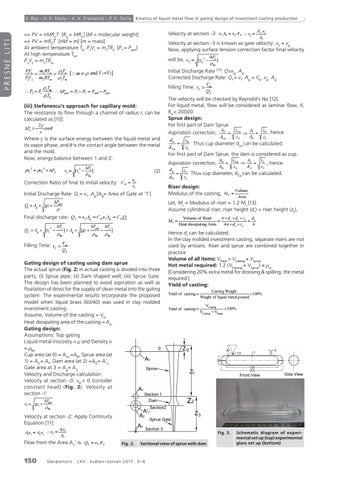
t f Qf Qf V Gating design of t f m casting using dam sprue The actual sprue (Fig. 2) in actual casting is divided into three Q f
parts, (i) Sprue pipe; (ii) Dam shaped well; (iii) Sprue Gate. The design has been planned to avoid aspiration as well as floatation of dross for the supply of clean metal into the gating system. The experimental results incorporate the proposed model when liquid brass (60/40) was used in clay molded investment casting. Assume, Volume of the casting = Vm Heat dissipating area of the casting = Am Gating design: Assumptions: Top gating Liquid metal Viscosity = µ and Density = = ρliq Cup area (at 0) = ACu =A0, Sprue area (at 1) = A S = A1, Dam area (at 2) =AD = A’2 Gate area at 3 = Ag= A 3 Velocity and Discharge calculation: Velocity at section -0: v 0 = 0 (consider constant head) (Fig. 2). Velocity at section -1:
VCasting Weight 100% Yield of of casting casting VCastingCasting Yield Yield of casting VCasting VSprue 100% 100% VCasting VSprue Weight of liquid metal poured Yield of casting
VCasting VCasting VSprue
100%
liq
A1v1 = A2 v2 ∴ v2 =
A1v1 A2 v2 v2
A1v1 A2
Q2 v2 A'2 Flow from the Area A 2’ is: Q2 = v2 A'2 A' v v3 A3 v2 A'2 v3 2 2 A3
v3 = vg
Casting Weight Casting Weight Yield of casting 100% Yield of casting Weight of liquid metal poured 100% Weight of liquid metal poured
Pgas
Velocity at section -2: Apply Continuity Equation [11]:
150
d r d r zs d r Hence drVolume can beofcalculated. Riser Mr Heat molded dissipatinginvestment Area 4 casting, 4 d r zs In the clay separate risers are not used by artisans. Riser and sprue are combined together in practice. VTotal = VCasting + VSprue =Casting VCasting VSprue Volume of all items: VTotal VTotal =V ++ VSprue 1.21.2 (VCasting +V ) ×) ×ρmρ Hot metal required: (VCasting + Sprue VSprue 1.2 (VCasting + VSprue) × ρm m [Considering 20% extra metal for drossing & spilling, the metal VTotal = VCasting + VSprue required.] 1.2 (VCasting + VSprue) × ρm Yield of casting:
A1v1 A2
Fig. 2. Sectional view of sprue with dam
S l é vá re ns t v í . L X V . k v ě te n – č e r v e n 2017 . 5 – 6
5
Calculated Filling Time
Experimented Filling Time Fig. 3. Schematic diagram of experi4 mental set up (top) experimental glass set up (bottom) 3 5
Filling Time (s)
v1 gz1
Area Area
C
2
Calculated Filling Time Experimented Filling Time
4
1
g Time (s)
PŘESNÉ LITÍ
A3
3
0 0.0
2
0.2
0.4
0.6
Percentage of Volume
0.8
1.0
2
v f [v g
P
liq