https://doi.org/10.22214/ijraset.2023.48787

11 I January 2023
ISSN: 2321-9653; IC Value: 45.98; SJ Impact Factor: 7.538
Volume 11 Issue I Jan 2023- Available at www.ijraset.com

https://doi.org/10.22214/ijraset.2023.48787
ISSN: 2321-9653; IC Value: 45.98; SJ Impact Factor: 7.538
Volume 11 Issue I Jan 2023- Available at www.ijraset.com
S. Nagasai1 , Md. Shoheb2 , B. Shashidhar Rao3 , Dr. Y. Srinivasul4, Dr. Krishna5 1, 2, 3Sreenidhi Institute of Science and Technology
4Assistant Professor, 5Professor, Dept. of Electronics and Communication Engineering, Sreenidhi Institute of Science and Engineering, Telangana, India

Abstract: The main end of the design is to measure the speed of trains and to insinuate it to the station control room TCAS, if the train exceeds it’s maximum speed limit. Then we will place two IR transmitter receiver dyads with some distance, along the road. And by calculating the time difference between the activation of two IR receivers as per the law sense, the speed of the train can be calculated. So now we will design the design in such a way that the regulator will be connived to the two IR receivers and to the GSM modem through a line motorist IC MAX232 for periodical communication.
Then GSM modem is used to shoot the SMS to the control room to insinuate about the overspeeds.However, the GSM modem sends corresponding data to the station control room TCAS as per the law sense, If any train crosses the speed limit means the time between the activation of two IR detectors is lower than the time limit.
Keywords: Arduino Uno, IR Sensor, GSM Module, IC MAX232, TCAS, LCD Display, LEDs
Thesystemisdesignedtorecordandreporton colorfulconditioningwithinaprocesscalledtheTrackingSystem. IntheRoboticscontrol system,thecontrolandoperation ofprecisespeedcontroloftheunstablesystemphasewheretherearedislocationsandfrictionparameters are attained using a wireless communication system.
When driving on rails, train motorists shouldn’t exceed the maximum speed limit allowed by their train. Still, accidents continue to do becauseofthespeedlimitbecausetrainmotoristsfrequentlyignoretheirrunningdetectors.Thisspeedchecker willbeveritablyusefulfor train controlroomTCAS drivers because it’llnot onlygive digitaldisplaydepending on thespeed ofthe train butalsosound an alarmif the train exceeds the speed limit.
ThesystemprincipallyhastwoIRdyads,locatedon theroadtracksoutdoors, withatransmitterandtwodyadsreceiverontheothersideof the road.
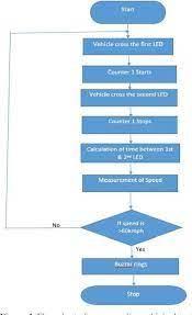
The system shows the time taken by the train to exceed this distance from one brace to another where the speed of the train can be calculated.Thetotaldistancebetweennightjittersandtimeistheintervalbetween crossingthefirstdetectorandthealternatedetector.The systeminstalledinatrain-locothresholdsworkingautomaticallyassoon asitdetectsanythinggoingwrongin movementofthetrain by transferring cautionstoallthe concerned authorities, including thetrain’smotorist, the comingroad station and others over a prescribed radio frequence.
Thissystemhasbeen designedassumingthatthemaximumadmissiblespeed for railroadsismoreover 40kmph or 120kmphasper the rules. Before operation, using a multimeter we’ve to check whether the power force affair iscorrect. However, applypower force to the circuit by flipping switch to ‘ on’ if yes. In the circuit, we use long cables for connecting the two printDIODEs, sothatwecantakethemoutofthePCBandinstallononesideoftheroad, 100measurespiecemeal. We’veinstalledtwo IRDiodetransmitters (similarasIRDiode firebugs)on theother sideoftheroadexactlycontrarytotheprintDIODEs similarthatIR Diode light falls directly on the print DIODEs. Reset the circuit by pressing RESET switch, so the display shows ‘0000’. Stationary TCASunitshallalsotransmittheMovementAuthoritytotheLocoTCASin itsgovernancein stationarea. Thelength ofthemovement authorityisdecidedgroundedonthesignalaspectoftheapproachingStopSignal.TheLocounitshallmakespeedprofile/boscagewind for differentsituationsgroundedonmovementauthority, speedrestrictionandotherinformation asenteredfromTracksidesub-system. TheLocoTCASunitshalldisplaythetrain speed,thepermittedspeed, thetargetdistanceandthetargetspeedtothelocoairmanthrough a motorist Machine Interface (DMI).
ISSN: 2321-9653; IC Value: 45.98; SJ Impact Factor: 7.538
Volume 11 Issue I Jan 2023- Available at www.ijraset.com
1) Arduino UNO: The Arduino UNO is built around the ATmega328P microcontroller. In comparison to other boards, such as the Arduino Mega, it is simple to use. The board is made up of digital and analogue I/O pins, shields, and other circuits. The Arduino UNO has six analogue input pins, fourteen digital pins, a USB connector, a power jack, and an ICSP (In-Circuit Serial Programming)header. It'swrittenin IDE, which standsfor IntegratedDevelopmentEnvironment.Itiscompatiblewith bothonline and offline platforms.

2) PC Microcontroller: PIC Microcontroller PIC16F877A is one of the most popular microcontrollers in the assiduity. This microcontroller is veritably easy to use, render or edit this regulator is also easy.


3) Proteus 8 Professional: Proteus 8 professional is a software which can be used to draw schematics, PCB layout, law and indeed pretend the schematic.
4) MPLAB X IDE: Proteus 8 professional software that can be used to draw schematics, PCB format, law and indeed system simulation.
ISSN: 2321-9653; IC Value: 45.98; SJ Impact Factor: 7.538
Volume 11 Issue I Jan 2023- Available at www.ijraset.com
5) IR Detectors: IR technologyis used in everydaylife and in the assiduityfor a variety of purposes. For illustration, TVs use an IR detector todescrysignals transmitted from a remote. The main advantages of IRdetectors are their low power consumption, their simplestructureandtheir simplefeatures.IRsymptomsaren’tdetectedbythemortaleye. IRshaftsintheelectromagneticfieldcan be set up in the regions of visible microwave oven. generally, the wavelengths of these swells range from0.7 µm 5 to 1000µm.
6) Buzzer: Sensor-Buzzer isabuzzerthatispassive. Itis likeamagneticspeaker,requiresvoltagewith differentfrequenciesinorderto produce sound. When the frequency increases, the pitch becomes louder.


7) Tv Display: The TV screen( Liquid Crystal Display) is an electronic displaymode with a wide range of operations. The 16x2 TV display is a introductory and extensively used in colorful bias and circuits. These modules are preferred over seven orders and numerous other LEDs. Reasons available LCDs are provident; fluently organized; there’s no limit to displaying special and customized characters (as opposed toseven orders), vitalityand further. 16x2TV meansit can displayup to16 charactersper line andthereare2similarlines. InthisTVeachletter isdisplayedon a5x7pixelmatrix. ThisTVhastworegisters,videlicet,Command and Data. The command register keeps the instructions given by the TV.

ISSN: 2321-9653; IC Value: 45.98; SJ Impact Factor: 7.538
Volume 11 Issue I Jan 2023- Available at www.ijraset.com
8) Arduino IDE Compiler: Arduinoisan open-sourceelectronicsplatformbuiltprimarilyon user-friendlyhardwareandsoftware.To upload our programme into the microcontroller, the Arduino IDE employs an AVR-GCC compiler and AVR-dude. The Arduino IDEisopen-sourcesoftwarefor writinganduploadingcodetoArduinoboards.TheIDEapplicationiscompatiblewithavarietyof operatingsystems, includingWindows, MacOSX, andLinux. ItiscompatiblewiththeprogramminglanguagesCandC++.IDEis an abbreviation for Integrated Development Environment.
Protection Functions
Prevention of Signal Passing at Danger ( SPAD)
1) StationaryTCASunitshallcalculatethemovementauthoritygroundedonthesignalaspector/andtrackcircuitstatusor/androute locking status, point position and the status of the berthing track circuit.
2) In caseofanyconflictbetween signalaspect, pointposition, berthingtracksection, signalaspectsequenceanddrum, theStationary TCAS unit shall transmit most restrictive aspect of that signal and shall reduce the movement authority consequently.
3) Stationary TCAS unit shall check route information configured on the base of the TCAS Control Table of the stationary TCAS Unit( banning overlaps.
ISSN: 2321-9653; IC Value: 45.98; SJ Impact Factor: 7.538
Volume 11 Issue I Jan 2023- Available at www.ijraset.com
While driving on India’s railroads, motorists shouldn’t exceed the speed limit. still, accidents do as a result of speeding as numerous motorists exceed the speed limit. An easy- to- manage rail speed checker is used and to describe possible train collisions on railroads withoutmortalintervention. TCASdriverstakeimmediateaction when thespeedlimitexceedsasthesystemprovidesdigitaldisplayand alarm todescryanyspeed of the train ifthe train exceeds the speed limit. Toovercome this problem, we’ve used a circuit called speed checker and overhead discovery. This program is cheap and easytoinstallandthere’s noneed for homemade monitoring. Ifthe speed limit falls the alarm is raised to alert TCAS officers to immediate action.


The design “TRAIN COLLISION AVOIDANCE SYSTEM ” has been successfully designed and tested. It has been developed by integrating features of all the tackle factors used. Presence of every module has been reasoned out and placed precisely therefore contributingtothestylish workingoftheunit. Secondly, usinglargelyadvancedICsandwiththehelpofgrowingtechnologythedesign hasbeen successfullyenforced. IndianRailroadshavesuccessfullypilotedACDsin thenortheastfrontierroad,covering,736kilometres (079 mi) of its broad hand route. They're now installing the ACDs on 760 kilometres (470 mi) of the Konkan Railway.

[1] Singh,P., Juneja,N., Kapoor,S., “ Using mobilephone detectorsto descry driving geste Proceedings ofthe3rd ACM Symposium on Computing for Development, 2013.
[2] FazeenM.,GozickB.,DantuR.,BhukhiyaM.,GonzalezM.C.,“ safe-deposit boxDriving UsingMobilePhones,”IEEEDealsonIntelligentTransportation Systems, 2012.
[3] ChigurupaS., PolavarapS., KancherlaY.,NikhathK.A., “ Integrated Computing System for measuring motorist Safety Index, ” International Journal of Emerging Technology and Advanced Engineering, 2012.

[4] JohnsonD.A.,TrivediM.M., “ Driving Style Recognition using a smartphone as a detector platform, ” IEEE 14th International Conference on Intelligent Transportation system, 2011.
[5] T DaiJ., TangJ., BaiX., ShenZ., XuanD., “ Mobile phone grounded drunk driving discovery, ” Proc. 4th Int. Conf. Pervasive Health NO warrants, 2010.
[6] VaibhavBhoyar,PriyankaLata,JuileeKatkar, AnkitaPatilandDeepaliJavale,“ SymbianBasedRashDrivingDiscoverySystem, ”InternationalJournalofArising Trends & Technology in Computer Science( IJETTCS), 2013