5 minute read
International Journal for Research in Applied Science & Engineering Technology (IJRASET)


ISSN: 2321-9653; IC Value: 45.98; SJ Impact Factor: 7.538
Volume 11 Issue III Mar 2023- Available at www.ijraset.com
Advertisement
E. Vertical Axis
The vertical axis passes through an aircraft from top to bottom. The rotation about this axis is called yaw. This yaw changes the direction the nose of the aircraft is pointing towards left or right. The primary control of yaw is with the rudder. Ailerons also have a secondary effect on yaw.
V.
Blockdiagram
The block diagram of the proposed UAV model is as shown in Fig. 5.1. The system consists of major components that include: Propulsion System, RC Transmitter and Receiver, Control surface, Power system, Flight Controller, Radio Telemetry, Video Telemetry and Global Positioning System
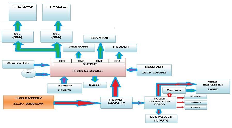
A. Propulsion system
The proposed model consists of two BLDC motors coupled with propellers that are used to generate thrust required to develop propulsive force for the propeller. The ESC are used to regulate the BLDC motors.
B. RC Transmitter and Receiver
Radio Transmitter is an electronic device that uses radio signals to transmit commands wirelessly via a set radio frequency over to the Radio Receiver, which is connected to flight controller of the UAV being remotely controlled.
C. Control surfaces
The three control surfaces namely rudder, ailerons and elevator which are being controlled using servo motors and flap mechanism.
D. Power System
The power system consists of lithium-polymer (Li-Po) battery as power source and a power distribution board with battery eliminator circuit (BEC) which steps down the voltage to 5V and supply other additional system & the direct battery supply is distributed to BLDC motors and First-person view( FPV) system.
E. Flight controller
The flight controller (FC) is the brain of the aircraft. It consists of a circuit board with a wide range of sensors that detect movement of the drone, as well as user commands. Using this data, it then controls the speed of the motors to make the craft move as instructed. It prevents the motor from turning when the pilot is not ready to fly (a safety feature). Also, it prevents take-off before the autopilot is fully configured and ready to fly.
ISSN: 2321-9653; IC Value: 45.98; SJ Impact Factor: 7.538
Volume 11 Issue III Mar 2023- Available at www.ijraset.com
F. First Person View (FPV) System
First-person view (FPV), also known as remote-person view (RPV), or video piloting, is a method used to control a radio-controlled vehicle from the driver or pilot's view point. Most commonly it is used to pilot a radio-controlled aircraft or other type of unmanned aerial vehicle (UAV). It consists of Radio telemetry and video telemetry.
1) Radio Telemetry: The radio telemetry refers to the scientific payload installed onto the UAV. This system uses a Software Defined Radio (SDR) front-end and is designed to communicate with the UAV during flight. This system provides us vital information of the UAV’s live status like acceleration, battery charge, height, pressure, GPS co-ordinates and operating mode which enables the system to determine the right course of action and helps us to recover the UAV when crashed.
2) Video Telemetry: Video telemetry provides real-time video footage from the FPV camera to the remote screen. There are 3 components in this system: FPV camera, Audio\Video Transmitter and Audio\Video Receiver.
G. Global Positioning System (GPS) module
The Global Positioning System (GPS) is a satellite-based navigation system that provides location and time information. A GPS module calculates its position by precisely timing the signals sent by GPS satellites and conveys the information to the flight controller.
VI.DESIGNANDANALYSISOFFIXEDWINGUNMANNEDAERIALVEHICLE
A. Hardware Components
The major components used in the fixed wing UAV are: Plane Body Design, BLDC Motors and appropriate ESC, Propellers, Servo motor & control horns, Radio Controlled Transmitter & Receiver, Flight Controller & GPS and Battery.
1) Plane Body Design: The technical data for the design of plane body is as follows: Minimum number of channels: 4, that includes Ailerons, elevator, rudder and throttle, Size of the plane body: 810 mm wing span and 640 mm length, Average maximum weight with battery: 495 gm, Centre of gravity: 46mm

52cm from the front of the wing
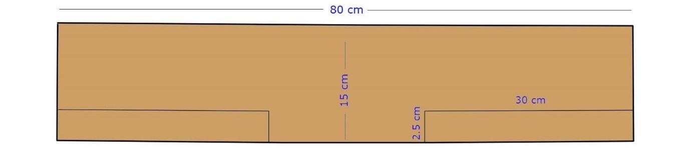
2) Fuselage: The fuselage is a long cylindrical shell, closed at its ends, which carries the internal payload. The dominant type of fuselage structure is semi-monocoque construction. These structures provide better strength-to-weight ratios for the central portion of the body of an airplane than monocoque construction. A semi-monocoque fuselage consists of a thin shell stiffened in the longitudinal direction with stringers and longerons and supported in the radial direction using transverse frames or rings measurements are shown in Fig. 6.1.
The strength of a semi monocoque fuselage depends mainly on the longitudinal stringers (longerons), frames and pressure bulkhead. The skin carries the cabin pressure (tension) and shear loads, the longitudinal stringers carry the longitudinal tension and compression loads, and circumferential frames maintain the fuselage shape and redistribute loads into the airframe shown in Fig. 6.2 The fuselage and most of the plane body will be built with foam board and 3D printed parts. Planes are drawn for parts made out of foam and 3D models using in .stl file for 3D printing. The Fuselage design from side view is shown in Fig. 6.3.
ISSN: 2321-9653; IC Value: 45.98; SJ Impact Factor: 7.538
Volume 11 Issue III Mar 2023- Available at www.ijraset.com
3)
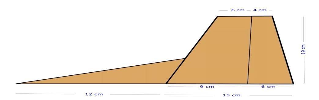
Elevators are flight control surfaces, usually located at the rear end of an aircraft, which control the pitch of the aircraft and along with the angle of attack and the lift of the wing. The design of the elevator is as shown in Fig 6.4 Rudder is a flight control surface, usually located at the rear of an aircraft, which control the yaw of the aircraft. Wing is an airfoil that helps lift a heavier-than-air craft. When positioned above the fuselage (high wings), wings provide an unrestricted view below and good lateral stability. The design and view of the Rudder is shown Fig. 6.5 and wing measurements are shown in Fig. 6.6
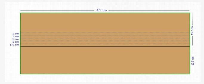
The wing rib is one of the lateral structural members of the larger wing structure. It provides required aerodynamic shape for the wing structure. The ribs are placed along the wing span dimension as shown in Fig. 6.7 and wing rib placements are shown Fig. 6.8
4) Servo Motor and Control Horns
Servo motors are used to provide actuation for various mechanical systems. Since they have high mechanical strength and low weight they are ideal for the control surfaces on a plane. Due to their affordability, reliability, and simplicity of control by microprocessors, they are used in robotics applications which is one of their advanced features
Flaps – Increase lift as shown in Fig. 6.9 but also increase drag. Using flaps, an aircraft can fly slower before stalling. Flaps are often used to steepen the landing approach angle and let the plane land at a slower touchdown speed (as well as letting the aircraft lift off at a slower takeoff speed).
5) Radio Controlled Transmitter and Receiver
A radio frequency transmitter-receiver board receives data and transmits it wirelessly to different components via its antenna. The wireless communication technique is extremely useful, especially for small scale applications where data exchange is required Radio control (often abbreviated to RC) is the use of control signals transmitted by radio to remotely control a device.