7 minute read
International Journal for Research in Applied Science & Engineering Technology (IJRASET)


ISSN: 2321-9653; IC Value: 45.98; SJ Impact Factor: 7.538
Volume 11 Issue III Mar 2023- Available at www.ijraset.com
Advertisement
The AOA sensor for small aircraft has two main components: a mechanism for measuring wind direction and a sensor for measuring the angle of rotation of the device. The mechanical design is asymmetric cross-sectional shape, NACA 009, that can operate with airspeed 10–30 m/s. AOA sensor with Pixhawk4 board is more preferred for electronic devices of electronic aircraft that must be lightweight, durable, and accurate. The design and the verification of a brushless DC motor is integrated into an actuator for aircraft applications. The electromagnetic design with thermal analysis has been carried out to verify the brushless DC motor temperatures during its operation. BLDC motors are more suitable for Aircraft as it is verified that the loads can be sustained for several minutes without exceeding the insulations temperature limits.
The Design Analysis and Considerations of Power Efficient Electronic Speed Controller (ESC) for Small-scale Quad-copter
Unmanned Aerial Vehicle [3], focuses on the power electronics design considerations of ESC for drones. Multiple power transistor technologies implementations Si-IGBT, SiC, and GaN are implemented to achieve the best flight time optimization. GaN technology appears to have the advantage of having the minimum loss across all throttle conditions.
The Development of a Dynamic Electronic Speed Controller for Multi-copter [4], discusses about a self-developed free programmable ESC equipped with a rotary encoder that is used for precise and dynamic speed control with a high-resolution position sensor in combination with a 72MHz microcontroller. This paper also provides details about assembly design and the mathematical modelling of the permanent magnet synchronous motors (PMSM) with a propeller for the multi-copter.
The implementation of ESC for multi-copter provides high dynamic and low energy consumption, with underlying flatness-based control during aviation. The proposed fixed wing UAV is estimated to be aviating efficiently and navigate with maximum accuracy. The airplanes are designed based on suitability of type of foam for light weight and durability. Also, various test models are built for different design features and recurring flight tests are conducted on these models based on their design specifications.
III.METHODOLOGY
A. Working principle
A plane's engines are designed to move the plane forward at high speed. That makes air flow rapidly over the wings, which throw the air down toward the ground, generating an upward force called lift that overcomes the plane's weight and holds it in the sky as shown in Fig 3.1. According to Newton's third law of motion, “For every action, there is an equal and opposite reaction” which explains how the engines and wings work together to make a plane move through the sky. The force of the hot exhaust gas shooting backward from the jet engine pushes the plane forward. That creates a moving current of air over the wings. The wings force the air downwards and this pushes the plane upward.
B. Aerodynamics
1) Pressure difference in Plain
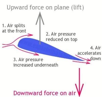
The wings make lift by changing the direction and pressure of the air that crashes into them as the engines shoot them through the sky. When air rushes over the curved upper wing surface, it has to travel further than the air that passes underneath to a principle of aerodynamics called Bernoulli's law, fast-moving air is at lower pressure than slow-moving air, so the pressure above the wing is lower than the pressure below, and this creates the lift that powers the plane upward shown in Fig 3.2.
Air goes Plane forwar
Aviation Model
3.2 Cross section of the aerofoil
According to Newton's third law of motion, if air gives an upward force to a plane, the plane must give an (equal and opposite) downward force to the air. So, a plane also generates lift by using its wings to push air downward behind it. That happens because the wings are not perfectly horizontal, but tilted back very slightly so they hit the air at an angle of attack. The angled wings push down both the accelerated airflow (from up above them) and the slower moving airflow (from beneath them), and this produces lift.
ISSN: 2321-9653; IC Value: 45.98; SJ Impact Factor: 7.538
Volume 11 Issue III Mar 2023- Available at www.ijraset.com
Since the curved top of the airfoil deflects (pushes down) more air than the straighter bottom (in other words, alters the path of the incoming air much more dramatically), it produces significantly more lift shown in Fig 3.3
Generally, the air flowing over the top and bottom of a wing follows the curve of the wing surfaces very closely and as the angle of attack increases, the smooth airflow behind the wing starts to break down and become more turbulent and that reduces the lift. At a certain angle (generally round about 15°, though it varies), the air no longer flows smoothly around the wing. There is a big increase in drag, a big reduction in lift, and the plane is said to have stalled.
2) Thrust in Plain
One crucial component of an airplane’s aerodynamics is the force of thrust. The propulsive force created by the propeller or rotor works to counteract the effects of two of the other four forces of flight -weight and drag as shown in Fig. 3.4.
If this weight is not accurately determined, it will affect the plane’s performance. It will also result in miscalculating the fuel volume needed for the flight, and even the plane’s ability to take off safely. If the plane cannot generate enough lift and thrust to compensate for the weight, then some weight must be removed. It is usually suggested to replace materials with stable, yet lighter materials or carry fewer passengers and less cargo, to reduce the excess load on the vehicle.
Fig: 3.3 Aerofoil subjected to difference in pressure Fig: 3.4 Air foil in Plains

An airplane’s propeller generates thrust by utilizing the principle of Newton’s Third Law, which states that for every action, there will be an equal and opposite reaction. A propeller or jet engine pushing air to the rear will have the effect of moving the plane forward unless some other force offers a force in the opposite direction. The plane’s propeller will push enough air past it to cause the aircraft to move in the opposite direction of this force. The propeller must work with a high level of efficiency to provide the necessary thrust for takeoff and flight. The mass of the fuel needed to power the propeller flight must also be accommodated. As the flight continues, fuel is consumed. As the fuel is consumed, its mass is reduced. As mass is reduced, less thrust is needed
3) Weight in Plain
One of the significant forces among the four forces of flight is weight. Weight is the force caused by gravity. This weight includes not only the aircraft itself, but also the mass of the cargo, fuel, pilot, and any passengers. Increased weight indicates that the aerodynamic forces of thrust and lift must also increase as shown in Fig 3.5 If this weight is not accurately determined, it will affect the performance of the plane. It will also result miscalculating the fuel volume needed for the flight and plane’s ability to take off safely.
4) Drag in Plain
Drag is a rear-facing force caused by the disruption of airflow over the wing, fuselage and other components of the plane. The force of drag must be overcome through the forward momentum of the aircraft. To reduce drag, it also needs to alter the design of the aircraft. The concept of Drag in Plane using Paper is shown in Fig 3.6. The curved shape of the wing creates lift by making the air move faster across the top of the wing and lowering the air pressure. This reduced pressure results in less force pushing down on the wing while maintaining an upward force under the wing, creating lift. It is important to note that these axes move with the aircraft, and change relative to the earth as the aircraft moves. For example, for an aircraft whose left wing is pointing straight down, its "vertical" axis is parallel with the ground, while its "transverse" axis is perpendicular to the ground.
ISSN: 2321-9653; IC Value: 45.98; SJ Impact Factor: 7.538
Volume 11 Issue III Mar 2023- Available at www.ijraset.com
On the other hand, the cup will catch the air and not allow it to flow past. Catching or trapping the airflow will result in much more drag. The shape of the plane will allow the air to continue in the direction it was initially flowing without much interruption.

IV.AIRCRAFT FLIGHTCONTROLSURFACES
Aircraft flight control surfaces are aerodynamic devices allowing a pilot to adjust and control the flight attitude of an aircraft The development of an effective set of flight control surfaces is one of the critical advances in the development of aircraft. Some of the early efforts at fixed-wing aircraft design succeeded in generating sufficient lift to get the aircraft off the ground, but once aloft, the aircraft proved uncontrollable, often with disastrous results. The development of effective flight controls is what allowed stable flight.
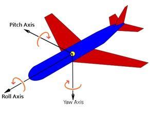
A. Axes of motion
An aircraft is free to rotate around three axes that are perpendicular to each other and intersect at its centre of gravity (CG). To control position and direction a pilot must be able to control rotation about each of them. The Axis of motion is shown in Fig 4.1.

B. Propeller
The propeller, coupled with the engine, is what produces enough thrust to move a plane forward. Once the plane is moving forward, the remaining four forces of flight combine to provide the necessary lift to get the aircraft in the air. These aerodynamic forces of flight, all working optimally together, result in an efficient and a safe voyage.
C. Transverse axis
The transverse axis is also referred to as lateral axis. It passes through an aircraft from front wingtip to rear wingtip. The rotation about this axis is called pitch. The pitch changes the vertical direction based on the nose of aircraft that is pointing towards. Among the flight control surfaces, the elevators are the primary control surfaces for pitch.
D. Longitudinal axis
The longitudinal axis passes through the aircraft from nose to tail. Rotation about this axis is called roll. The angular displacement about this axis is called bank. The pilot changes bank angle by increasing the lift on one wing and decreasing it on the other. This differential lift causes rotation around the longitudinal axis. The ailerons are the primary control of bank. The rudder also has a secondary effect on bank.