https://doi.org/10.22214/ijraset.2023.49663

11 III
2023
March
ISSN: 2321-9653; IC Value: 45.98; SJ Impact Factor: 7.538
Volume 11 Issue III Mar 2023- Available at www.ijraset.com

https://doi.org/10.22214/ijraset.2023.49663
ISSN: 2321-9653; IC Value: 45.98; SJ Impact Factor: 7.538
Volume 11 Issue III Mar 2023- Available at www.ijraset.com

1Assistant Professor, Department of EEE, Sree vahini institute of science and Technology Tiruvuru., NTR District., Andhra Pradesh, India

2, 3, 4, 5 6UG scholar students Sree vahini institute of science and Technology, Tiruvuru., NTR District., AP, India
Abstract: Batteries from electric vehicles (EVs) can be used as potential energy storage systems in micro-grids. By storing energy when there is an excess (grid-to-vehicle) and supplying energy back to the grid (vehicle-to-grid), they can aid in micro-grid energy management. It is necessary to establish appropriate infrastructure and control mechanisms in order to implement this idea. This study presents an architecture for level-3 EV quick charging in a Vehicle to Grid-Grid to Vehicle system on a microgrid. A DC rapid charging station is modelled as part of a test micro-grid system for connecting EVs. Vehicle to Grid-Grid to Vehicle power transfer is demonstrated through simulation research. According to test results, EV batteries actively regulate power in the micro-grid using Grid to Vehicle and Vehicle to Grid operating modes. The controller provides good dynamic performance in terms of dc bus voltage stability, and the charging station design ensures minimal harmonic distortion of gridinjected current.
Key words: grid-connected inverter, micro-grid, off-board charger, and DC quick charging in electric vehicles.
A micro-essential grid's components include energy storage devices since they make it possible to include intermittent renewable energy sources. When plugged in for charging, the batteries of electric vehicles (EVs) can be used as efficient storage devices in micro-grids.
The majority of personal transportation vehicles are idle assets because they are often left parked for around 22 hours per day. By storing excess energy (Grid-to-Vehicle) and returning it to the grid when it is needed, Electric Vehicles may be able to assist with micro-grid energy management (Vehicle-to-Grid). Vehicle to Grid applied to the general power grid has some limitations, including being difficult to control, requiring a significant number of Electric Vehicles, and being difficult to implement quickly [1]. In this instance, a Vehicle to Grid system is simple to implement in a micro-grid.
Three charging levels for EVs are specified by the Society of Automotive Engineers. The on-board charger of the car is connected through a connection to a typical household (120 V) outlet for level 1 charging. If you drive less than 60 kilometres per day and have the entire night to charge, this is the slowest type of charging that you may use. In order to supply power at 220 V or 240 V and up to 30 A, level 2 charging uses dedicated Electric Vehicle Supply Equipment (EVSE) at home or at a public station. DC fast charging is another name for level 3 charging. DC fast charging stations cut the charging time to 20 to 30 minutes by offering charging power of up to 90 kW at 200 or 450 V. Due to the quick power transfer needed when Electric Vehicles are used as energy storage, DC quick charging is preferred for the implementation of a Vehicle to Grid architecture in micro-grids. The system can incorporate renewable generating sources using the DC bus as well.
The Vehicle to Grid idea has been used in the general power grid in the majority of earlier studies for services including peak shaving, valley filling, regulation, and spinning reserves [2]. A micro-grid facility's Vehicle to Grid development to handle power generation from sporadic renewable energy sources is still in its early stages. In the majority of the works mentioned [3], level 1 and level 2 ac charging are also used for Vehicle to Grid technology. The power rating of the on-board charger sets a restriction on these AC charging solutions.
The distribution grid's lack of design for energy flow in both directions is another problem. In this case, research is required to create technically sound charging station architectures that will support Vehicle to Grid technology in micro-grids. The solar photovoltaic (PV) array is integrated into the micro-grid using the same DC bus that is used to interface electric vehicles. Using offboard chargers, the proposed architecture enables high-power, bi-directional charging for Electric Vehicles. The effectiveness of the suggested model is assessed using simulations in MATLAB and Simulink for both the Vehicle to Grid and Grid to Vehicles modes of operation.
ISSN: 2321-9653; IC Value: 45.98; SJ Impact Factor: 7.538


Volume 11 Issue III Mar 2023- Available at www.ijraset.com
Figure 1 [4] depicts the layout for a DC rapid charging station to integrate Vehicle to Grid-Grid to Vehicle infrastructure in a microgrid. Off-board chargers are used to link EV batteries to the DC bus. The dc bus is connected to the utility grid by a grid-connected inverter using an LCL filter and a step-up transformer. This is a description of the charging station's key components.
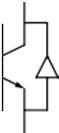
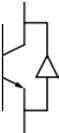
The chargers are off-board and placed in an EVSE for DC fast charging. The fundamental component of an off-board charger with Vehicle to Grid functionality is a bidirectional dc-dc converter. It creates the connection between the DC distribution grid and the EV batterysystem. Fig.2 shows the converter arrangement. Two IGBT or MOSFET switches are used, and they are always switched on by complementary control signals.


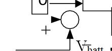
1) Charging Mode (Buck Mode Operation): The converter acts as a buck converter by stepping down the input voltage to the battery charging voltage when the upper switch ( ) is activated. Current passes through the switch and inductor to the battery when it is turned on. This is the charging process, in which power is transferred from the grid to the car (G2V). When the switch is closed, the circuit is completed by the current flowing back via the lower switch's inductor and diode. The battery voltage can be calculated as follows if D is the higher switch's duty ratio:
Vbatt = Vdc *D (1)
2) Discharging Mode (Boost Mode Operation): The converter acts as a boost converter by stepping up the battery voltage (Y) to the DC bus voltage while the lower switch (X) is in operation (Z). When the switch is in the on position, current flows via the inductor, the anti-parallel diode of the upper switch, and the capacitor to complete the circuit. In this instance, the battery is operating in discharge mode, and the net power flow is from the vehicle to the grid. The output voltage during boost mode of operation can be calculated using the following formula if the capacitor is large enough to supply a constant dc voltage: (2)

where is the duty cycle of the lower switch.


B.
The grid-connected inverter (GCI) allows the reverse flow of current through the anti-parallel diodes of the switches in each leg in addition to converting the dc bus voltage into a three-phase ac voltage (Fig. 1). The output terminals of the inverter are linked to an LCL filter for harmonic reduction and to produce pure sinusoidal voltage and current. This work's design process for working out the LCL filter characteristics is derived from [4].
ISSN: 2321-9653; IC Value: 45.98; SJ Impact Factor: 7.538


Volume 11 Issue III Mar 2023- Available at www.ijraset.com
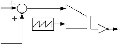
Fig 3 shows the implementation of a constant current control technique [5] employing PI controllers for charge and discharge management of the battery charger circuit. In order to decide between charging and discharging modes of operation, the controller must first compare the reference battery current with zero in order to identify the polarity of the current signal. The reference current and measured current are compared after the mode has been chosen, and the error is then sent through a PI controller to produce the switching pulses for Sbuck and Sboost. While charging and draining, Sboost and Sbuck will both be off.
For the inverter controller, a cascade control in a synchronous reference frame is provided. Figure 4 [4] shows the standard delivery vector control employing four PI controllers in a closed loop. Two outside voltage control loops and two inner current control loops make up the control structure. Both the active ac current and the d-axis bus voltage are controlled by the inner loop of the d-axis.


Similar to this, the q-axis inner current loop adjusts the reactive current, which in turn regulates the ac voltage magnitude. To improve system efficiency during transients, the dQ decoupling terms W and feed-forward voltage signals are also used.


Figure 5 shows the configuration of the micro-grid test system with the DC quick charging station. The system's generation sources provide a 50kW solar PV array and a 100 kW wind turbine (WT). The EV battery storage system involves four EV batteries connected through off-board chargers to a 1.5 kV DC bus of the charging station. Using a boost converter with an MPPT controller, the solar PV is additionally connected to this DC bus. A 25 kV distribution feeder and a 120 kV equivalent transmission system make up the utility grid.
The micro-grid is connected to the doubly-fed induction generator powered by a wind turbine at the point of common coupling (PCC). Transformers are used to increase the voltage and connect each AC system to the utility grid.
ISSN: 2321-9653; IC Value: 45.98; SJ Impact Factor: 7.538

Volume 11 Issue III Mar 2023- Available at www.ijraset.com

The design for charging stations is based on [4], and the appendix contains the obtained parameter values. When the wind turbine is running at its rated speed, it can produce 100 kW of power. The maximum power output of the solar PV system is 50 kW when operating under standard test parameters (1000 W/m2 irradiance and 250C temperature). The 480 V ac bus is connected to a resistive load rated at 150 kW. For unity of operation, the reactive current reference to Grid Connected Inverter is set to zero. The EV batteries' initial state of charge (SOC) is 50%. The Vehicle to Grid-Grid to Vehicle power transfer is carried out by operating the batteries of EV1 and EV2 (Fig. 1) once steady state conditions have been obtained. Table I displays the current set-points applied to the battery charging circuits for the EV1 and EV2 batteries, and the outcome is shown in the following figures:
In figure 6 and 7 we can see the simulation circuit diagram for vehicle to grid technology and the control scheme diagram to control charging and discharging of electric vehicle batteries. In Figs. 8 and 9, respectively, the battery parameters for EV1 running in Vehicle to Grid mode and EV2 operating in Grid to Vehicle mode are displayed.


ISSN: 2321-9653; IC Value: 45.98; SJ Impact Factor: 7.538


Volume 11 Issue III Mar 2023- Available at www.ijraset.com
Fig. 10 shows the active power contribution from various system components. The grid's power adjusts to take into account the electricity that EVs are transferring. The grid power from 1 to 4 is negative polarized, indicating that the car is feeding electricity into the system. Grid power is supplied by the grid to charge the vehicle's battery, as evidenced by the change in polarity at 4 seconds. This exemplifies how the Vehicle to Grid-Grid to Vehicle process works. Also, the PCC's net power is zero, demonstrating the system's ideal power balance. The inverter controller's outer voltage control loop, which is seen in Fig. 11, regulates the dc bus voltage at 1500 V. This is accomplished through the inner current control loop, which is seen in Fig. 12, tracking the altered d-axis reference current.


ISSN: 2321-9653; IC Value: 45.98; SJ Impact Factor: 7.538

Volume 11 Issue III Mar 2023- Available at www.ijraset.com
The grid-injected current is given to total harmonic distortion (THD) analysis, with the outcomes reported in Fig. 13. Harmonic current distortion in power systems 69 kV and less is limited at 5% THD, in accordance with IEEE Std. 1547. Grid-injected current has a THD of 2.31%, which is made possible by the LCL filter's smart design. Fig. 14 shows the grid voltage and current at PCC. Voltage and current are in phase during Grid to Vehicle operation and 1800 out of phase during Vehicle to Grid operation indicating the reverse power flow.


This paper summarizes the model and design of a Vehicle to grid system in a micro-grid using a dc quick charge architecture. To connect EVs to the micro-grid, a dc quick charge station with off-board chargers and a grid connected converter is proposed. The power electronic interface's control mechanism enables two-way power transmission between EVs and the grid. According to the simulation results, there is a flawless power transfer between EVs and the grid, and the EVs' grid-injected current meets all necessary requirements.
The designed controller exhibits good dynamic performance in terms of tracking the modified active power reference and dc bus voltage stability. In this study, active power regulation components of the micro-grid are considered. The developed Vehicle to Grid system may also be used for reactive power management and frequency regulation, among other services. Additional study is advised to design a supervisory controller that sends command signals to the various EV charging controllers.
1) Feedback system can be given to the control system by replacing the PI controllers with PID Controllers

2) Artificial neural networks, fuzzy logic controllers andAnfis controller scan be used for charging and discharging

ISSN: 2321-9653; IC Value: 45.98; SJ Impact Factor: 7.538
Volume 11 Issue III Mar 2023- Available at www.ijraset.com
[1] Shumei, L. Xiaofei, T. Dewen, Z. Qianfan, and S. Liwei, “The construction and simulation of V2G system in micro-grid,” in Proceedings of the International Conference on Electrical Machines and Systems, ICEMS 2011, 2011, pp. 1–4.
[2] S. Han, S. Han, and K. Sezaki, “Development of an optimal vehicle-to-grid aggregator for frequency regulation,” IEEE Trans. Smart Grid, vol. 1, no. 1, pp. 65–72, 2010.
[3] M. C. Kisacikoglu, M. Kesler, and L. M. Tolbert, “Single-phase on-board bidirectional PEV charger for V2G reactive power operation,” IEEE Trans. Smart Grid, vol. 6, no. 2, pp. 767–775, 2015.
[4] A. Arancibia and K. Strunz, “Modeling of an electric vehicle charging station for fast DC charging,” in Proceedings of the IEEE International Electric Vehicle Conference (IEVC), 2012, pp. 1–6.
[5] K. M. Tan, V. K. Ramachandra murthy, and J. Y. Yong, “Bidirectional battery charger for electric vehicle,” in 2014 IEEE Innovative Smart Grid TechnologiesAsia, ISGT ASIA2014, 2014, pp. 406–411.
ISSN: 2321-9653; IC Value: 45.98; SJ Impact Factor: 7.538


Volume 11 Issue III Mar 2023- Available at www.ijraset.com
P.Jyothi obtained her Bachelor of Technology in Electrical and Electronics Engineering in Bonam venkata chalamaih engineering college odalarevu, amalapuram, East Godavari dist, completed Mtech through GATE in sree vahini institute of science and technology, tiruvuru, Andhra Pradesh, India. Her areas of interest are power systems, Electrical machines and linear integrated circuits.
B. Dhanunjaya obtained his Bachelor of Technology in Electrical and Electronics in sree vahini institute of science and technology from JNTUK, Tiruvuru, Andhra Pradesh, India. His areas of interests are Power Systems, Electrical utilization and traction, Electrical Estimation
Ch.Venkateswara rao obtained his Bachelor of Technology in Electrical and Electronics in sree vahini institute of science and technology from JNTUK, Tiruvuru, Andhra Pradesh, India. His areas of interests are power systems, Electrical machines and Electrical drives.
V. Praveen obtained his Bachelor of Technology in Electrical and Electronics in sree vahini institute of science and technology from JNTUK, Tiruvuru, Andhra Pradesh, India. His areas of interests are Power Electronics, Electrical machines and control systems
S. Sunil obtained his Bachelor of Technology in Electrical and Electronics in sree vahini institute of science and technology from JNTUK, Tiruvuru, Andhra Pradesh, India. Hisareas of interests are Power Electronics, Electrical Distribution system and power systems.


P. Thrisha obtained her Bachelor of Technology in Electrical and Electronics in sree vahini institute of science and technology from JNTUK, Tiruvuru, Andhra Pradesh, India. Her areas of interests are Power Electronics, Electrical Devices and circuits, switch gear and protection