INTERNATIONAL JOURNAL OF INNOVATIVE TECHNOLOGY AND CREATIVE ENGINEERING (ISSN:2045-8711) VOL.2 NO.9 SEPTEMBER 2012 3.4
Computation of reverse route in RREP
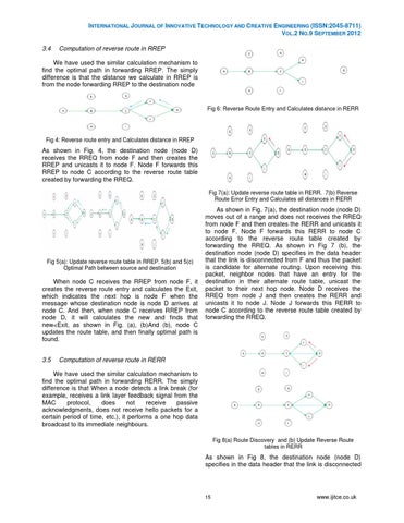
We have used the similar calculation mechanism to find the optimal path in forwarding RREP. The simply difference is that the distance we calculate in RREP is from the node forwarding RREP to the destination node
Fig 6: Reverse Route Entry and Calculates distance in RERR
Fig 4: Reverse route entry and Calculates distance in RREP
As shown in Fig. 4, the destination node (node D) receives the RREQ from node F and then creates the RREP and unicasts it to node F. Node F forwards this RREP to node C according to the reverse route table created by forwarding the RREQ. Fig 7(a): Update reverse route table in RERR. 7(b) Reverse Route Error Entry and Calculates all distances in RERR
Fig 5(a): Update reverse route table in RREP. 5(b) and 5(c) Optimal Path between source and destination
When node C receives the RREP from node F, it creates the reverse route entry and calculates the Exit, which indicates the next hop is node F when the message whose destination node is node D arrives at node C. And then, when node C receives RREP from node D, it will calculates the new and finds that new<Exit, as shown in Fig. (a), (b)And (b), node C updates the route table, and then finally optimal path is found. 3.5
As shown in Fig. 7(a), the destination node (node D) moves out of a range and does not receives the RREQ from node F and then creates the RERR and unicasts it to node F. Node F forwards this RERR to node C according to the reverse route table created by forwarding the RREQ. As shown in Fig 7 (b), the destination node (node D) specifies in the data header that the link is disconnected from F and thus the packet is candidate for alternate routing. Upon receiving this packet, neighbor nodes that have an entry for the destination in their alternate route table, unicast the packet to their next hop node. Node D receives the RREQ from node J and then creates the RERR and unicasts it to node J. Node J forwards this RERR to node C according to the reverse route table created by forwarding the RREQ.
Computation of reverse route in RERR
We have used the similar calculation mechanism to find the optimal path in forwarding RERR. The simply difference is that When a node detects a link break (for example, receives a link layer feedback signal from the MAC protocol, does not receive passive acknowledgments, does not receive hello packets for a certain period of time, etc.), it performs a one hop data broadcast to its immediate neighbours. Fig 8(a) Route Discovery and (b) Update Reverse Route tables in RERR
As shown in Fig 8, the destination node (node D) specifies in the data header that the link is disconnected
15
www.ijitce.co.uk