STUDY OF ATTENUATION AND BENDING LOSSES IN SIGNAL TRANSMISSION OVER STEP INDEX MULTIMODE PMMA
FIBERS
A.Z.M. Touhidul Islam1 and Md. Firoz Ahmed2
1Department of Electrical and Electronic Engineering, University of Rajshahi, Rajshahi-6205 Bangladesh
2Department of Information and Communication Engineering, University of Rajshahi, Rajshahi-6205 Bangladesh
ABSTRACT
Plastic optical fibers (POFs) are highly promising transmission media for short distance optical communication in transmitting information from source to destination by sending light pulses. Compared to glass optical fibers, POFs offer many advantages such as low cost, huge flexibility and ease of installation In contrast, POFs have the drawback of their relatively high loss. Accordingly, a continued research on the loss analysis of plastic fiber based optical fiber communication systems is necessary to examine their performance in data transmission This paper deals with an experimental study of signal attenuation and bending loss arising from signal transmission over a set of step index multimode polymethyl methacrylate (PMMA) plastic optical fibers of dissimilar length
KEYWORDS
Plastic Optical fibers, PMMA step indexed multimode cable, Attenuation, bending loss
1. INTRODUCTION
Optical fiber communication has been widely used due to its high performance attributes of low attenuation, high security, high information capacity, high sensitivity, longer life span, compact size, low cost, ease of maintenance, low interference, and high reliability over long distances[12]. The non-conductive optical fibers offer very high bandwidth through a combination of dense wavelength division multiplexing and optical amplification. Fibers can be connected to each other through connectors or splicing techniques [3].
Glass optical fibers are easily broken and have very small core diameter, which makes them very difficult to interconnect, unsuitable for self installations and very expensive. In contrast, plastic optical fiber (POF) has shown its suitability for short distance data communication such as digital car networks, industrial networks, and home networks. POFs comprise the advantages of large corediameter, operate at the visible region of the spectrum, require less expensive and simpler components, and so on [4, 5].More than 6 million users in the United States, 17 million in Japan, 10 million in Korea and 40 million worldwide are using direct fiber optic connections to the home or building [6]. The network installation in homes and offices using POF is very simple compared with glass fibers enabling ease of maintenance [7]. In addition, larger numerical aperture (NA) of POFs makes it easy to couple light from light sources into the fiber.
POFs are manufactured from materials such as polymethyl methacrylate (PMMA), polystyrene (PS) and polycarbonates (PC) and so on. These materials have transmission window in the visible
International Journal of Ambient Systems and Applications (IJASA) Vol.8, No.1/2, June 2020
region of the spectrum Transmission losses due to absorption and scattering of light over these wavelengths are very high and, thus, POF can only be used for short-distance data transmission[8]. Most of the commercially available POFs use PMMA as their core materials [4]. However, during signal transmission through optical fiber it faces signal attenuation and several losses, which reduce the performance of the optical communication system. There are many reasons causing attenuation in the fibers like absorption, dispersion, scattering, bending, splicing and connectors, as well as can be affected by temperature variations. Consequently, continued research and development on the core materials used in POFs are necessary for improving their performance significantly.
The objective of this paper is to investigate attenuation and bending losses in signal transmission over PMMA step index multimode fiber optic cable Power losses caused by signal propagation through the fiber of different length and bending of the fibers are studied using Scientech 2502 Fiber Optic Communication TechBook module. Impact of fiber bends on signal attenuation is studied for different number of turns and bending loop diameter of the fibers
The rest of the paper is organized as follows. In section 2 deals with related works. Section 3 describes the optical fiber communication model. Section 4 describes the basics of step index PMMA Plastic Optical Fibers. Losses in plastic optical fiber are discussed in Section 5. Section 6 describes the experimental procedures. Experimental results and discussion are presented in section 7 and finally section 8 concludes the paper.
2. RELATED WORKS
A comprehensive introduction to the most significant features of POFs is given in [9]. Koike et al. reviewed article that reviewed the status of POF developments in the last half century where they have focused on loss reduction and bandwidth enhancement techniques [10].The important applications of optical fibers made of Polymethyl methacrylate(PMMA) material with Step-Index (SI) profile is presented in [11].
Ravi et al. discussed different types of dispersions in an optical fiber in [3]. They concluded that dispersion can be avoided by using smaller core diameters which allows fewer modes. And also usage of single mode fiber permits no modal dispersion. Effect of bend loss in large core multimode optical fiber communication system is analyzed in [12] by varying the core diameter of the fiber, the bend radius of the fiber and the wavelength of the laser used. They showed that as the core radius of the fiber increases, the bend loss increases, increasing the numerical aperture decreased the bend loss, and also noticed that as the wavelength increases, the bend loss increases and vice-versa. Authors in [13] reviewed both intrinsic and extrinsic loss mechanisms in optical fiber They argued that intrinsic losses are associated with the chemical and physical structure of the fiber materials used in the fiber, while extrinsic losses are related to losses due to contaminants and presence of production imperfections. Loss of optical power in a single-mode optical fiber due to bending has been investigated for a wavelength of 1550 nm in [14].
Authors in [15] found that the attenuation is less significant when use a light wavelength of 850 nm compared with 660 nm. A novel, time-of-flight based technique, is presented in [16] for accurately measuring the dispersion of highly dispersive optical fibers. In order to predict how an optical fiber communication system’s component and channel will function, computer-aided modeling and simulation are essential tools. Authors in [17] investigated various transmission effects on pulses propagation in optical communication systems utilizing MATLAB programming. Dispersion and attenuation effects are explored with the simulation of Gaussian
International Journal of Ambient Systems and Applications (IJASA) Vol.8, No.1/2, June 2020
pulse propagation through single mode optical fiber and their simulation results indicate that these effects increase with increasing the distance of propagation over the fiber
3. OPTICAL FIBER COMMUNICATION SYSTEM
A block schematic of an optical fiber communication system is shown in Figure 1. This system conveys either the analog or digital signal from the information source to the destination over the optical fiber cable. The information source provides an electrical signal to a transmitter comprising the driver circuit, optical source and channel coupler. The optical source provides the electrical
optical conversion. It can be either a semiconductor laser or light-emitting diode (LED). The signal transmission medium consists of an optical fiber cable. The receiver consists of a channel coupler, photo-detector and electronic circuits for linear channel and decision circuit. Photodiodes may be used for the detection of the optical signal and the optical–electrical conversion and finally the electrical signal reach the destination.
4. BASICS OF STEP INDEXED MULTIMODE PMMAFIBERS
Plastic optical fiber (POF) is an optical fiber which are made from materials such as polymethyl methacrylate PMMA (n=1.49), polystyrene (n=1.59), polycarbonates (n=1.5-1.57), fluorinated polymers, and so on. POFs use harmless green or red light that are visible to the eye and can be safely installed in a home. POF provides low cost solutions to short-distance applications such as local area networks and high-speed internet access.
The most common core material for POF is PMMA. It’s refractive index is 1.492. PMMA based POF usually work with visible light (red, green and blue). The cladding materials for POF are Fluorinated Polymers or Fluorinated PMMA; the refractive index is in the order of 1.42. Due to large refractive index difference between the code and classing, numerical apertures of upto 0.50 are attained. The available PMMA step index POF has a core diameter of 980 μm, and a total (core plus cladding) diameter of 1mm. The PMMA POFs commonly use red LEDs which lie in the transmission window centered at 650 nm.
5. LOSSES IN PLASTIC OPTICAL FIBER
5.1. Attenuation
Attenuation is the reduction or loss of optical power as light travels through an optical fiber. Signal attenuation is defined as the ratio of optical input power (Pi) to the optical output power (Po) and it can be expressed in dB as:
International Journal of Ambient Systems and Applications (IJASA) Vol.8, No.1/2, June 2020
Attenuation can also be expressed in terms of input and output voltages as ����������������������,�� = 20������
The basic attenuation mechanisms in a POF can be classified into two main groups: intrinsic and extrinsic. Among the intrinsic losses, there are the absorption of the constituent material and the Rayleigh scattering. Absorption and scattering losses depend on the composition of the optical fiber and, therefore, they cannot be eliminated and represent the ultimate transmission loss limit Absorption losses are caused by the molecular vibrational absorption of the groups C H, N H, and O H and by the absorption due to electronic transitions between different energy levels within molecular bonds. The Rayleigh scattering loss is caused by the scattering arising from composition, orientation, and density fluctuations [20]
Among the extrinsic losses there are the absorption caused by both metallic and organic pollutants and the scattering irritated by dust particles, microfractures, bubbles, and other structural imperfections in the POF [18]. in addition, there are also radiation losses, originated by perturbations (both microscopic and macroscopic) in the fiber geometry. Whenever the POF is bent with a finite curvature radius, radiation losses occur.
Attenuation depends on the fiber type and the operating wavelength. Single mode fibers have lower attenuation than multimode fibers. The higher the operating wavelength, the lower the attenuation. For the PMMA POFs, two absolute minima of attenuation can be observedlocated at 522 and 570 nm (green), although there is a relative minimum around 650 nm (red). Consequently, it is a general practice to use red lasers or fast high luminosity red LEDs with PMMA POFs, which lie in the attenuation window centered at 650 nm.
The attenuation also depends on the fiber core diameter, which increases as the core diameter decreases. It also dependson the spectral width and numerical aperture (NA) of the light source employed. An increase in the spectral width or in the source’s NA gives higher attenuation [19].
5.2. Bending Losses
When bending a fiber, the incidence angles of light beams at the boundary between the core and cladding changes. Consequently some beams get emitted from the fiber because the condition of total reflection is not achieved and, thus, an excess of attenuation appears. Depending on the bend radius of curvature, bending loss is classified into two: microbend loss or macrobend loss.
Microbending are small microscopic bends of the fiber axis that can be generated at any stage during the manufacturing process, the cable installation process or during services. They occur due to environmental effects, particularly, temperature variations. Microbending introduces slight surface imperfections which can cause mode coupling between adjacent modes and in turn creates radiation loss.
Macrobending occurs when a fiber is subjected to significant amount of bending above a critical value of curvature (the curvature is large compared to the fiber diameter), for example, those produced when rolling the fiber on a reel. The large bend curvature creates an angle that is too sharp for the light to be reflected back into the core, and some of it escapes from the core of the fiber into the cladding, causing attenuation. Macrobends are mainly produced during the POF installation process. When the curvature is small, losses are practically negligible. Ref. [9] reported that as the bend radius decreases radiation power losses increase exponentially for a full turn in a typical PMMA step index POF.
6. EXPERIMENTAL PROCEDURE
Experiments have been carried out to investigate power losses resulting from signal transmission in PMMA step index multimode fiber based optical fiber communication system. The experiment is divided into two parts: in the first part signal attenuation is observed while the bending loss is investigated in the second part. The equipmentsand components required for the experiments are (i) Scientech 2502 TechBook optical fiber communication learning platform, (ii) Dual Trace Analog Oscilloscope and (iii) Fiber optic cable of different lengths of 0.5, and 1.0 m, (iv) Mandrel, (v) connecting leads etc. A list of technical specifications of Scientech 2502 TechBook are as follows. Optical Source:LED having peak emission wavelength of 660 nm; function generator:1.1 KHz Sine wave;cable type :step index multimode PMMA plastic cable;refractive index:core (1.492), cladding (1.406);numerical aperture:better than 0.5; acceptance angle:better than 60 degrees; fiber diameter:1000 microns;fiber length:0.5 m and 1 m.
Following procedures are followed for the measurement.
a) Function Generator’s 1 KHz sine wave output was connected to the emitter input E1 socket via connecting lead.
b) The 0.5 m optic fiber cable was connected between emitter 1 output and detector l’s input.
c) One channel of the oscilloscope (CH1) was connected to the output of function generator to observe the source (input) signal. To observe the destination (output) signal, another channel (CH2) of the oscilloscope was connected to the output D1 socket of the detector.
d) Power Supply of the TechBook and Oscilloscope was switched ON.
e) The function generator’s signal frequency and voltage were set to have a 1 KHz and 2 Vp-p, respectively.
f) The attenuation was calculated using the following equation ����������������������,�� = 20������10
Where Vi = input (source) voltage and Vo = output (destination) voltage
g) The experiment was repeated for different length of the fiber (0.5 and 1.0 m) without disturbing any other setting.
h) For the bending loss measurement (i.e. to observe the impact of bending on attenuation), the fiber optic cable was wrapped on mandrels and observes the corresponding output signal. The experiment was repeated for various looping diameters and the numbers of turns for each fiber separately.
7. RESULTS AND DISCUSSION
7.1. Study of Attenuation
To measure attenuation in optical fiber, we used two PMMA SI multimode optical fiber cables of length of 0.5 m and 1 m. In each case the source signal and the destination signal are observed on the screen of the oscilloscope and recorded. The fibers were tried to keep straight during this measurement. It was seen that, for each fiber, the voltage measured at the output of the detector is lower than input voltage. In addition, with increasing fiber length from 0.5 meter to 1 meter, the output voltage drops more and the attenuation increases. These results of attenuation versus length of the fiber are shown graphically in Fig. 2. From the graph it is evident that as the length of the fiber increases, the signal experiences more power loss. Similar results were obtained in a simulation study of optical fiber made of plastic and glass in [15]. As the attenuation is characterize by a logarithm relationship between the optical input and output power in an optical fiber system [21,22], in a straight fiber, the power of the transmitted signal decrease exponentially with distance.
The attenuation of signal in a POF results from both the intrinsic and extrinsic loss mechanisms [9,12,18] Signal attenuation may also results from other fiber loss mechanisms such as coupling loss, radiation loss due to fiber bending, fiber degradation with aging, as well as dispersion [23]. The study of attenuation versus fiber length is essential since the level of attenuation of signals in POF at a particular wavelength determines the maximum distance of an optical connection where signals requiring amplification.
7.2. Study of Bending Losses
Bending loss is investigated for different length of the fiber considering the following two cases:

(i) keeping the bending loop diameter fixed, the number of turns (or wrapping turns) is varied and
(ii) keeping the number of turns fixed, the bending loop diameter is varied.
7.2.1. Dependence of Number of Turns of the Fiber
The bending number of turns of the optical fiber cable of length 0.5 m is varied keeping the bending loop diameter fixed at 2 cm and the destination voltage at the output of the detector is recorded It was seen that as the number of turns increases the output voltage decreases and thus the bending loss increases The experimental procedure is repeated with a set of fiber cables of length of 0.5 m and 1 m. Figure 3 shows the graphical representation of the recorded results. From the figure, it is observed that the bending loss increases, for each fiber, with the increase of bending number of turns. It is also noticeable that for a fixed number of turns, the loss is greater for the fiber of higher length as compared to lesser length fiber optic cable. An increase in number of turns results in more bending a fiber and hence more loss. It is therefore necessary to maintain a small number of bends when installing the optical fiber network
7.2.2. Dependence of Bending Loop Diameter of the Fiber
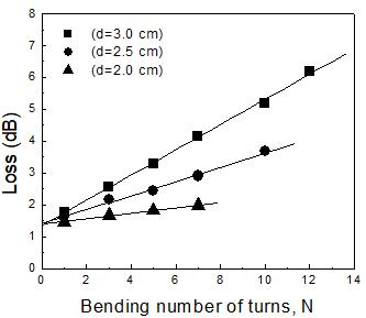
Bending loss is also investigated for various bending loop diameter of the fiber. Keeping the bending loop diameter fixed at 2 cm, the number of turns of the optical cable of length 1 m is varied and the destination voltage at the output of the detector is recorded. It is seen that as the bending number of turns increases the output voltage decreases and the bending loss increases. The experimental procedure is repeated with different bending loop diameters of 2.0 cm, 2.5 cm, and 3.0 cm for the same optical fiber cable. Figure 4 shows the graphical representation of these results. A linear behavior between bending loss and bending number of turns is obtained, and the slope of the obtained lines depends on the diameter of curvature. Similar result was obtained in Ref. [14]. It is also apparent that for a fixed number of bending number of wrapping turns, the bending loss is greater for lower bending loop diameter of the fiber and vice-versa.

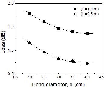
The bending loss for the two PMMA fiber optic cables is also studied by varying the bending loop diameter for a fixed bending number of turns for both the cables. At first, the bending loop diameter of the fiber of length 0.5 m is varied keeping the bending number of turns fixed at 1 and the destination voltage at the output of the detector is recorded. It is seen that as the bending loop diameter increases the output voltage increases and the loss decreases. The experimental procedure is repeated for different fibers of lengths of 0.5 m and 1 m. Figure 5 shows the graphical representation of these results. It is seen that the bending loss decreases exponentially with increasing of bending loop diameter for a fixed wrapping number of turns for each fiber. This exponential power decay characteristic is also observed in Ref. [9]. It is also observable that for a fixed bending loop diameter, the loss is greater for the fiber of higher length as compared to lesser length fiber.