The SSR system operates in the L-band at 1030 MHz in the transmit mode and at 1090 MHz in the receive mode. The operational features of the SSR system are laid down in the publication 'Aeronautical Telecommunications' Annex 10. Vol. 1 of the International Civil Aviation Organization (ICAO). The typical SSR equipment consists of dual interrogator-receivers. dual SSR plot extractors and automatic test and changeover facilities. Modern equipment is of entirely solidstate design and modular in construction. The current requirements of the Cyprus ATC system are limited to the use of Modes 3A and C. however. the system shall be capable of expansion to cater for future operations in Mode
The SSR antenna assembly is required to operate on top of the L-band primary radar antenna. A principal feature anticipated is a sharp cut off of radiation pattern at the horizon. which reduces excessive ground reflections. The existence of the latter may result in a number of undesirable effects. such as missed aircraft targets at certain elevation angels. false aircraft targets. and/ or split targets. Recent SSR antenna designs of the open planar array type have proved to possess several features which are becoming increasingly desirable as air traffic expands and SSR becomes more sophisticated and automated. The main features are: Sharp cut off. - High quality monopulse pattern. - 'Integral' side-lobe suppression (SLS) pattern.
S. The provision of a far field SSR transponder preferably installed at Nicosia
ATCC will provide an independent monitor I check of the performance of the whole SSR system. Plot extracted information and digital messages SSR and PR systems will be evaluated in the sense of aircraft identification and target tracking. The processed radar data together with control signals will be subsequently fed to appropriate data modems for transmission to the Nicosia ATCC and Larnaca Airport. Transmission may be effected via telephone channels over the microwave links operating between the radar head site and the aforesaid centers. A monitor display is required for use at the radar head site preferably capable of displaying analogue video as well as synthetics. The main objective of this monitor display unit is to enable engineering adjustments to be carried out on the radar system.
Nicosia ATC Center J.nt.onoo Coqt.rol
S1gnol Proceuor II, PloL Ext.net.or "9"
Duplicated Tra.ck Procoaaor
llodom•
~¥ ~ j ..~., ~::~~:. (
Txlll,
~
Un!L
~
~-.,-.,--,.,,-ho-p---~-
•
1: )
'o'
R4dsr D11ta rroce1110 ing:
Jl4dsr Do.t.11
Hecording RAdo.r Doto.
®
Di111t.ribut.ion Unit
@
J.1,1\.0RO\DOUIJ
llAdQ.r
Uo.t.o
l'rucao111ng
L
_I I
L ____
J
r--I
L-
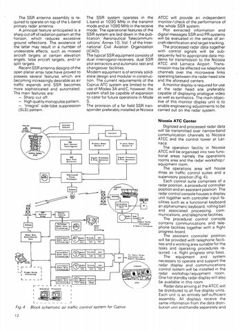
Fig. 4
12
JlAcJnr Cont.r (D)
l'4dor
Cont.r
(C)
I I
Flia:ht. St.rip Procu.olnii
(A)
CT)
- -·1
: r -
Roda.r Cont.r•
©,
,luLonoaouo l\Gdor Do.to. l'rocoooing:
lodor
ont.r
(Sup)
Procod. Control
Asa. Co11t.ro1
(A)
(A)
Pruccd. Cu11t.rol (D)
Cunt.rul (D)
l'roccuJ. Cont.rol
Ao11. Control
I-----,
A.1111.
(C)
(C)
Procod, Cont.ru1>----~
(Sup)
----,
aa, Sic::iulot.or
- -
Procooonr
- - - -
-
.J
Block schematic air traffic control system for Cyprus
Digitized and processed radar data will be transmitted over narrow-band communication channels to Nicosia ATCC and the control tower at Larnaca. The operation facility in Nicosia ATCC will be organized into two functional areas namely the operations rooms area and the radar workshop/ equipment room. The operations area will house three air traffic control suites and a supervisory position (Fig. 4 ). Each control suite comprises of a radar position. a procedural controller position and an assistant position. The radar control console houses a display unit together with controller input facilities such as a functional keyboard an alphanumeric keyboard. rolling ball and associated processing. communications. and telephone facilities. The procedural control console contains communications and telephone facilities together' with a flight progress board. The assistant controller position will be provided with telephone facilities and a working area suitable for the tasks and operating procedures required. i.e. flight progress strip bays. The equipment and system necessary to operate and support the radar display and communications control system will be installed in the radar workshop/ equipment room. One hot standby radar display will also be available in this room. Radar data arriving at the ATCC will be distributed to all five display units. Each unit is an entirely self-sufficient assembly. All displays receive the same information from the data distribution unit and handle separately and