ng the thrust for a toggle mechanism.
molding machines, and coining machines all make use of toggle mechanisms. There are three methods creating toggle force. They are single lever, double lever anchored and double lever scissors. Fig. illustrates a single lever toggle force mechanism with a moving pivot at the rod end, allowing the cylin rod to extend and retract in a horizontal plane. Toggle force is exerted upward in a vertical plane as Die casting machines, injection rod extends. The cap end of the cylinder is often mounted to a pivot.
anisms are used where high locking forces are required. hines, and coining machines all make use of HYDRAULIC toggle mechanisms. There are three methods of SELECT COMPONENTS FOR SYSTEMS le force. They are single lever, double lever anchored and double lever scissors. Fig. 3-5 ingle lever toggle force mechanism with a moving pivot at the rod end, allowing the cylinder and retract in a horizontal plane. Toggle force is exerted upward in a vertical plane as the Fig.1: A cylinder used to The cap end of the cylinder is often mounted to a pivot. operate a toggle mechanism
Calculating the Thrust for a Toggle Mechanism
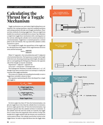
Toggle mechanisms are used where high locking forces are required. Die casting machines, injection molding machines, and coining machines all make use of toggle mechanisms. There Fig. 3-5 A Cylinder Used to Operate a Toggle Mechanism are three methods of creating toggle force. They are single lever, For a single lever the upward force of the toggle can be calculated from the tangent of the angle double-lever anchored, and double-lever scissors. Fig.1toggle, illustrates opposite between the lever arms and a single-lever toggle force mechanism with a moving pivot at the horizontal: TanθFig. = 3-5 A Cylinder Used to Operate a Toggle Mechanism adjacent the rod end, allowing the cylinder rod to extend and retractFor in a single lever toggle, the upward force of the toggle can be calculated from the tangent of the an opposite between the lever arms and the horizontal: a horizontal plane. Toggle force is exerted in a vertical Where “o”upward (opposite) = the vertical direction and “a” (adjacent) =Tan theθ horizontal direction. = adjacent plane as the rod extends. The cap end of the cylinder is often The hypotenuse is equal Where to the“o” length (opposite) = the vertical direction and “a” (adjacent) = the horizontal direction. mounted to a pivot. of the lever arm. Knowing remaining Fig.2: Force exerted For a single-lever toggle, the upward force of the toggle can strokea length, the adjacent side (a) and is equal by Fig. 3-5 A Cylinder Used to Operate Toggle Mechanism The hypotenuse to athe length toggle be calculated from the tangent of the anglethe between the lever applying Pythagorean Theorem, of the lever arm. Knowing remaining ever toggle,arms the and upward force of the toggle be calculated the tangent ofadjacent the angle length, side (a) and thecan opposite side offrom thestroke triangle (o)the the horizontal: opposite applying the Pythagorean Theorem, ever arms and the horizontal: may be calculated: Tanθ = the opposite side of the triangle (o) adjacent 2 SEL E C T2 COMP2 ONEN T S FOR H Y DR AUL IC S YS T EMS
be calculated: Hypotenuse = adjacent may + opposite “o” direction (opposite)and = the“a” vertical direction and “a” (adjacent) 2 2 2 pposite) = theWhere vertical (adjacent) = the horizontal direction. Hypotenuse 2 Or: Lever Arm = vertical axis2 = + adjacent + opposite 2 to the length = the horizontal direction. The hypotenuse equal horizontalisaxis 2 2 Or: Lever Arm = vertical axis + se is equal of the length 2 the lever arm. Knowing remaining stroke length, the adjacent horizontal axis The to equation representing the force developed by a single arm toggle is: arm. Knowing remaining The Pythagorean Theorem is usually side (a) and applying the Pythagorean Theorem, the opposite 2 2 2 the adjacent side (a) and though it has written as c = a + b , The Pythagorean Theorem is usually side of the triangle (o) may be calculated: as c2 = a2 + b2, though it has been rewritten here inwritten an attempt Pythagorean Theorem, F = Single toggle force Single toggle force N Single 2 been here inFst an=attempt st lb. to clarify therewritten toggle side of the triangle (o)2 = adjacent2 + opposite Or: the concept of Eq.Hypotenuse to clarify the concept of the toggle F = F i TAN θ toggle mechanism. ated: st 2 = vertical cyl axis2 + horizontal axis2 3.3Lever Arm mechanism. FCyl = Cylinder force N force. F = Cylinder force Cylwritten as c2 = a2 + b2, lb. 2 Pythagorean Theorem is usually = adjacent2 +The opposite The action of a cylinder rod extending Fig. 3-6 Force Exerted by a Toggle The action of a cylinder rod extending Fig. 3-6 Force Exerted by a Toggle though it has been rewritten here in an attempt clarify the horizontally to to exert a horizontally toggle force to exert a toggle force Arm2 = vertical axis2 + ° from the horizontal For lever angles less than 45 plane, single arm toggle force is less than the cylinder vertically is shown in Fig. 3-6. concept of the toggle mechanism. vertically is shown in Fig. 3-6. s2 ° force The in action extension; for lever angles greater than 45 from the horizontal plane, toggle force is greater than of a cylinder rod extending horizontally to exert a ean Theorem is usually force vertically is shown in3Fig.2. the toggle cylinder rod force in extension. As the cylinder 3 - 6 • Hydraulic Specialist Certification Study Manual - 6 • Hydraulic Specialist Certification Study Manual • 04/20/18 = a2 + b2, though it has Fig.3: A toggle mechanism The equation representing the as force by the a single nears the end of its stroke it developed extends, toggle en here in an attempt with two equal length armis toggle is: times the magnitude of the rod force. e concept of the toggle lever arms force many
Fst = Fcyl • TANθ
In Fig. 3-7 the double lever toggle method with the a cylinder rod extending Fig. 3-6 Force Exerted by a Toggle o exert a toggle forceanchored at a pivot point is shown. bottom arm Fst = Single toggle force lb. hown in Fig. 3-6.
The cylinder must free force to pivot as the toggle Fcyl be = Cylinder lb. moves. In order to input full thrust into the toggle ic Specialist Certification Study Manual • Single toggle force when the toggleFst =reaches the vertical overcenter N Fcyl = Cylinder N position, the cylinder must force be mounted so that its axis is perpendicular to the toggle when the toggle Single Toggle Force. is at the overcenter point. If the cylinder is not perpendicular when the toggle is at the overcenter less than 45° from the horizontal plane, sinpoint,Foritlever willangles be acting at an angle to the load and gle arm toggle force is less than the cylinder force in extension; its thrust into the toggle will be reduced. for lever angles greater than 45° from the horizontal plane, toggle force is greater than the cylinder rod force in extension. As When using nears a double toggle, the system the cylinder the endlever of its stroke as it extends, the togglemust be kept in balance (Fig. 3-7). A double lever toggle force is many times the magnitude of the rod force. In Fig.3 the system will require twice the force to lift a load double-lever toggle method with the bottom arm anchored at as a single system. Thusmust thebefollowing a pivot lever point is shown. The cylinder free to pivot equation as the moves. In order to input full thrust into the toggle when can toggle be used: 52
JUNE 2019
04/20/18
Study Manual • 04/20/18
Fig. 3-7 A Toggle Mechanism with Two Equal Length Lever Arms WWW.FLUIDPOWERJOURNAL.COM • WWW.IFPS.ORG
• 04/20