steel) that are appropriate to the material. One such example is the Tösssteg footbridge in WinterthurWülflingen built 1934 at Zürich, Switzerland (see Fig. 2). This slender elegant 38 m polygonal arch bridge (rise-to-span ratio = 1: 10.84) had a stiff deck girder that also formed a base for the iron railings (Baus and Schlaich, 2008). The arch slab and the cross walls are each 140 mm thick and the stiffening girder is 540 mm thick. Due to a slight reverse curvature at both ends, the transition to the shore is especially elegant. Fritz Leonhardt, one of the most experienced experts on reinforced concrete and bridges, first designed the aesthetic footbridge at Enzsteg in Vaihingen, Germany, during 1962. Many of the later footbridges were either stress ribbon bridges or cable stayed bridges.
Fig. 2: The Tösssteg footbridge, Zürich, Switzerland (http:// commons.wikimedia.org/)
3.1 Stress Ribbon Footbridges Stress ribbon structure represents the simplest structural form in which the suspension cables are embedded in the deck and follows a catenary arc between supports. Such structures can either be cast in-situ or formed of precast units. In the case of precast structures, the deck is assembled from precast segments that are suspended on bearing cables and shifted along them to their final position. Prestressing is applied after casting the joints between the segments to ensure sufficient rigidity of the structures. The first concrete stress ribbon bridge for pedestrians was built in Bircherweid, Switzerland, in the mid 1960s by Rene Walther (stress ribbon bridges are not the cheapest option as large foundations are required for anchoring the tension forces developed in the structure). Other notable stress ribbon bridge is in Geneva, Lignon-Loex, Switzerland, built in 1971. Jiří Stráský, one of the experts in stress ribbon bridges, also designed a multi-span stress ribbon bridge near Prague (1985) and the Maidstone Footbridge in UK (2001), with a change of direction at mid-span The Bridge and Structural Engineer
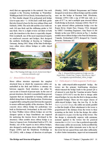
(Stráský, 2005). Schlaich Bergermann and Partner designed several stress ribbon bridges and the notable ones are the bridge at Enzauen Park, Pforzheim, Germany (1991) with a sag of 800 mm only on a span of 67.7 m, and a multiple span stressed ribbon North Bridge in Rostock, Germany (2003). The 87.43 m span stressed ribbon pedestrian bridge over the Rogue River, Grants Pass, Oregon, USA, designed by OBEC Consulting Engineers, Gary Rayor & Jiří Stráský in the year 2000 is shown in Fig. 3. Another notable stress-ribbon bridge is the Punt da Suransuns, Viamala, Switzerland (1997) designed by Conzett, Bronzini, Gartmann AG.
Fig. 3: Stressed Ribbon pedestrian bridge over the Rogue River, Grants Pass, Oregon, USA (Source: http:// en.wikipedia.org/wiki/Stressed_ribbon_bridge)
3.2 Cable-stayed or Cable-suspended Footbridges In the cable-stayed/cable-suspended bridge, the towers are the primary load-bearing structures which transmit the bridge loads to the ground. [It is of interest to note that the Venetian inventor Fausto Veranzio (1551-1617) was the first to design cable stayed bridges- he was also the first to design modern suspended bridge]. There are two major classes of cable-stayed bridges: harp, fan (see Fig. 4). In the harp or parallel design, the cables are nearly parallel so that the height of their attachment to the tower is proportional to the distance from the tower to their mounting on the deck. In the fan design, the cables all connect to or pass over the top of the towers. The fan design is structurally superior with minimum moment applied to the towers but for practical reasons the modified (semi) fan is preferred especially where many cables are necessary. In the modified fan arrangement the cables terminate near to the top of the tower but are spaced from each other sufficiently to allow better termination, improved environmental Volume 45 Number 3 September 2015 31