
ICW
Technical Manual KEY MEASURES
2
CONTENTS
3
4 1.0 Introduction 1.1 Suitability of Materials and Workmanship 1.2 Guidance for Design and Construction Methods 07 14 16 2.0 Inspections 2.0 Introduction 2.1 Site and Construction Overview 2.2 Excavations 2.3 Foundations to Ground Floor 2.4 Ground Floor to Upper Floor 2.5 Upper Floor to Roof Structure 2.6 Pre Plaster and Plaster Board 2.7 Completion 19 20 21 24 25 27 30 31 34 3.0 Site Investigation 39 4.0 Invasive Plants 45 5.0 Foundations 5.1 Strip and Trench Foundations 5.2 Minimum Depth of Strip Foundations 5.3 Concrete Mix 5.4 Stepped Foundations 5.5 Engineered Foundations 5.6 Engineered Fill 5.7 Piled Foundations 5.8 Raft Foundation 5.9 Foundations and Trees 5.10 Construction Principles 51 53 54 55 57 57 57 58 67 68 70 6.0 Substructure 6.1 Walls below DPC 6.2 Damp Proof Course 6.3 Service Penetrations 6.4 Pipes Bedded into Walls 6.5 Pipes Lintelled through Walls 6.6 Basements 6.7 Podium Decks 73 75 76 77 77 77 78 90 7.0 Drainage 7.1 Excavations 7.2 Access and Connection 7.3 Connections 7.4 Gullies 7.5 Bedding Material 7.6 Backfill Material 7.7 Flexible Pipes 7.8 Drainage Systems 7.9 Above Ground Drainage 7.10 Drainage Layout 7.11 Ventilation 7.12 Testing 95 97 98 100 100 101 101 102 103 104 105 106 107 CONTENTS
5 11.0 Roofs 11.1 Bracing and Restraint 11.2 Fire Stopping 11.3 Spandrel Panels 11.4 Roof Coverings 163 165 167 168 172 12.0 Timber Frame 12.1 Sole Plate 12.2 Fixing 12.3 Thermal Insulation 12.4 Vapour Control 12.5 Movement Control 12.6 Cladding 183 194 200 204 206 208 210 13.0 Insulating Concrete Formwork (ICF) 215 14.0 Modern Methods of Construction 225 15.0 Internal Services 15.1 Space Heating 15.2 Windows and Doors 15.3 Escape Windows 15.4 Safety Glazing 233 238 239 240 241 16.0 Conversion 16.1 Site and Construction Overview 16.2 Foundation to Ground Floor 16.3 Strip Out and Assessment of Original Structure 16.4 Superstructure to Upper Floor 16.5 Upper Floor to Pre Plaster including Roof Structure 16.6 Completion 243 245 249 251 253 257 264 17.0 Conversion Guidance 17.0 Introduction 17.1 Assessment Process 17.2 Substructure 17.3 Superstructure 271 272 274 275 280 18.0 Tolerances and Finishes 297 19.0 Technical Definitions 305 20.0 Acknowledgements 321 8.0 Ground Floors 8.1 Ground Bearing Floor Slabs 8.2 Precast Beam and Block Floors 8.3 Suspended Timber Floors 8.4 Damp Proof Membrane 8.5 Radon Gas Barrier 109 111 112 113 114 115 9.0 Superstructure 9.1 Exposure 9.2 Bricks 9.3 Blocks 9.4 Masonry Protection 9.5 Mortars 9.6 General Advice on Cavity Wall 9.7 Solid Wall 9.8 Cavity Wall 9.9 Lateral Restraint 9.10 Lateral Restraint Straps 9.11 Wall Ties 9.12 Cavity Closers 9.13 Movement Joints 9.14 Structural Openings 9.15 Cavity Trays & DPCs 9.16 Floor Joists 9.17 Engineered Wood and I Joists 9.18 Notching & Drilling 9.19 Floor Decking 9.20 Particle Boarding 9.21 Staircases 9.22 Internal Walls 9.23 Fire Resistance 9.24 Sound Insulation 9.25 Pre Completion Testing 9.26 Robust Details 9.27 Chimneys 117 119 120 120 121 122 122 123 124 125 126 126 127 128 129 130 131 132 135 137 137 138 139 141 142 143 143 144 10.0 Cladding 10.1 Timber Boarding 10.2 Timber 10.3 Plywood 10.4 Tile and Slate Cladding 10.5 Other Cladding 10.6 Weather Resistance of Walls and Cladding 10.7 External Treatment 10.8 Internal Treatment 10.9 Interstitial Condensation 10.10 Surface Condensation 10.11 Control of Moisture Penetration 10.12 Thermal Insulation of Walls and Claddings 10.13 Render 10.14 Further Guidance 147 149 152 153 153 154 154 154 155 155 155 155 156 157 161
7 1.0 INTRODUCTION
1.0
INTRODUCTION
To satisfy the requirements of this manual you must comply with:
• The applicable technical Building Regulation requirements which will be dependent upon the geographical location (i.e. when reference to the UK - England and Wales, Scotland and Northern Ireland) and the relevant transitional technical bulletins and updates.
• All other statutory technical requirements e.g. Water Regulations, the Gas (Installation and Use) Regulations, etc.
• The additional requirements set by ICW.
• The market acceptance and CML benchmark for structural lifespan is 60 years. However, it is also accepted that materials that are not of the structure will require maintenance and/or replacement within this period.
When interpreting the Requirements and Guidance the standards of construction achieved shall never fall below the minimum standard set by the controlling Building Regulations.
Requirements
This Technical Manual is divided into several sections corresponding to the various areas of construction. The ICW requirements and other statutory constructional requirements are shaded for ease of identification. These Requirements are in addition to compliance with Building Regulations and for the avoidance of doubt compliance with the Requirements is mandatory.
All dwellings, covered by a warranty from ICW, shall comply with the Requirements in force at the time that documents for the dwelling were deposited with the relevant authority for the purposes of the Building Regulations. The pages following the Requirements provide guidance on showing compliance.
For the purpose of this Manual, the term Building
Regulation refers to the equivalent or corresponding statute in the various geographical countries covered by this manual (for the UK - England and Wales, Scotland, Northern Ireland). Where a Building Regulation requirement is not currently applicable in a country, it shall be treated as an ICW requirement.
Building Regulation requirements are described in functional terms (in italic text) and reference is made to any corresponding regulation in England & Wales, Scotland and Northern Ireland. Where a Building Regulation requirement is not currently applicable in a country, it shall be treated as an ICW requirement.
In determining whether compliance with the Requirements has been achieved:
• It is for the building control body (Local Authority or Approved Inspector) to satisfy themselves on the compliance of plans and work with the Building Regulations. It should be noted that where a dispute arises, ICW has the right to delay the issuing of the Insurance Certificate until settled.
• For the avoidance of doubt, when several standards are referred to, the higher standard shall apply unless previously agreed in writing by the ICW Technical Department.
• The decision of ICW shall be final determining these Requirements.
8
1.0
ICW Requirements
The Construction shall comply with the Building Regulations.
Paths and drives shall be laid to falls and be adequately drained.
Site fill and consolidation of subsoil under paths, outbuilding, etc. Shall be carried out using non-organic materials and achieve an appropriate level of compaction suitable for the final finish.
Where on-site sewage treatment and disposal systems and/or soakaways are proposed, a porosity test shall be carried out to ensure that the ground conditions are suitable for that form of drainage discharge.
Subsoil drainage shall be provided within the vicinity of outbuildings, hardstandings, paths, drives and the like if the ground is liable to waterlogging or if the presence of a water table is likely to affect the stability of the ground.
Subsoil drainage shall be provided in garden areas if the ground is liable to constant waterlogging with 4 metres of the dwelling.
Garden areas shall be laid to levels and gradients appropriate to the levels of the buildings, adjacent highways and services.
An adequate method of rainwater disposal shall be provided to all permanent outbuildings:
External doors and windows shall be designed and constructed to:
• Provide an adequate deterrent to forced entry into a dwelling.
• Be weather-tight.
• Shed water from the building in an effective manner.
• Be provided with a draught strip.
The enveloping walls and floors of a dwelling, including jambs, sills and heads of door and window frames, shall be designed and constructed so as to:
• Prevent the build-up of excessive condensation within the fabric of the construction.
• Prevent cold bridges causing local surface condensation to occur, and prevent the excess flow of air into a dwelling.
The width of internal stairways shall be such as to offer safe passage to users of the building. The following accommodation and amenities shall be provided to a dwelling:
• Adequate whole house heating and domestic hot water supply.
• Electrical installation with an adequate number of lighting points and socket outlets, signed off on completion with an Electrical test certificate.
• Gas supply to kitchen cooker position (where a mains supply passes adjacent to the dwelling), signed off with a Gas Safe certificate.
• Adequate storage space at each floor level.
9 1.0
ICW Requirements
Building service installations shall be designed and constructed so that they:
• Operate in a safe manner.
• Are provided with adequate controls to allow their operation, isolation and drainage.
• Are provided with adequate means of access where necessary for the purposes of adequate inspection, maintenance and replacement.
All service installations requiring periodic attention by the user shall be provided with adequate operating and maintenance instructions and be included within the handover manual.
Finishes to walls, floors, fixtures and ceilings in conjunction with levelling and supporting surfaces should provide adequate resistance to impact, wear, water, and light chemical attack, due account being taken of the location of the element. In addition, externally located finishes should have resistance to frost and ultra-violet radiation.
Decorative elements shall be completed to adequate basic levels of visual quality (higher standards which may be agreed between the builder/developer and the purchaser are not included in this Requirement)
Adequate vehicular and/or pedestrian access shall be provided:
• From an adjacent street, to an entrance of the dwelling and to any garage or other parking area within the curtilage of the site paying particular attention to gradients to comply with the local authority regulations.
• From the dwelling to any garage and outbuilding.
Detached garages and outbuildings shall be:
• Structurally stable and withstand movement of the subsoil, due account being taken of the ground conditions and wind exposure for the site.
• Reasonably restraint to rain and ground water.
Retaining walls and garden walls shall be stable, withstand movement of the subsoil and be adequately protected from the adverse effects of ground moisture and freezing. In addition, retaining walls shall be constructed so as not to allow the build-up of ground water. Planning permission consent may be required if the wall is over a certain height or next to a road or pathway
All external ramps and steps providing access to a dwelling shall be safe to use.
Garden areas shall be reasonably cleared of builders materials prior to handover.
Accuracy, quality of finish and protection:
• Any element covered by another element shall be finished to adequate standards in order to properly receive the covering element and be adequately protected prior to being covered up.
• Any element not covered up by another element shall be provided to an adequate basic standard of visual finish and protected prior to handover, (higher standards which may be agreed between the builder/developer and the purchaser are not included in this Requirement).
10
1.0
ICW Requirements
Design and construction:
• Adequate investigations shall be carried out to identify design data which vary from site to site. Total and differential movement of an element shall be adequately limited or accommodated, such that damage does not occur to itself or to other elements.
• Methods of fixing, jointing, bonding, supporting, tying together, surface preparation and sealing of elements shall be adequate, due account being taken of the location and anticipated life of the element.
• The design and construction of any element and choice of materials shall be such that a reasonable level of safety to persons is provided.
• The method of achieving compliance with any Requirement shall not result in the failure to comply with another Requirement.
• Any element which performs the role of more than one element shall comply with the Requirements applicable to each element.
• Every dwelling shall be cleared of builders materials and debris and adequately cleaned prior to handover.
Durability – Materials and workmanship:
• All materials, except for decorative materials, shall have a minimum life span of not less than 30 years for items affecting structural stability and 10 years for non-structural items, due account being taken of their intended location and use.
• Materials shall be adequately treated to prevent their premature decay or decomposition and adjacent materials shall be compatible with each other.
• Materials shall be stored, protected and properly treated prior to being incorporated into the dwelling.
• The requirements shall be met whilst the building is in service.
Where deemed necessary the developer/builder should commission a comprehensive survey and report by an Expert for the structure of the building or elements of structure, to indicate the condition and lifespan of those elements.
Provision of integral damp-proof course and damp-proof membrane to provide an effective barrier against rising damp. Any damp proofing products must have an insurance backed guarantee acceptable to ICW otherwise these works will be excluded from cover.
Where alterations, repairs or replacement of flat roof coverings are part of the works during a conversion, these works must also have an insurance backed guarantee acceptable to ICW otherwise these works will be excluded from cover.
11 1.0
ICW Requirements
Independent inspection and treatment of timbers against fungal and insect attack, where necessary, together with replacement of all rotting timbers and associated work necessary to remedy the cause of dampness. Timber treatment to include an insurance backed guarantee, acceptable to ICW.
Historic buildings shall achieve as reasonable, as is practicable level of sound insulation. The results of the “test and declare” testing shall be displayed in the building.
Other Statutory Requirements
All elements of construction covered by this Manual shall comply with any relevant statutory requirements.
Services passing through the building envelope shall comply with the requirements of the relevant Gas, Water, Electricity and Drainage Authorities.
The protection of building services supplies and installations in waterlogged ground shall satisfy the requirements of the Supply Authority.
The method of on-site sewage treatment and disposal shall comply with the requirements of the Sewage / Water Authority / Environment Agency.
The method of discharge of a private drain or sewer into a public sewer shall comply with the requirements of the Sewage Authority / Environment Agency.
The ventilation of voids under ground floor slabs shall be to the satisfaction of the local Gas Authority.
Every dwelling shall be provided with a wholesome supply of drinking water to the satisfaction of the Water Authority.
Heating appliances shall comply with the requirements of the Local Authority with regard to the Clean Air Acts (smokeless zone requirements).
The location of services within the finishes shall comply with the requirements of the Gas, Water, Electricity and Drainage Authorities.
12
13 1.0
1.1 SUITABILITY OF MATERIALS AND WORKMANSHIP
Establishing Fitness of Materials and Workmanship
The following methods exist for establishing the fitness and assuring the quality of materials and workmanship.
Construction Products Directive
The CE mark is a claim that a product, when properly used, enables the construction works in which it is incorporated to meet the relevant essential Requirements of the EC Construction Products Directive; the claim is normally based on compliance with a harmonised European Standard or European Technical Approval.
The essential Requirements encompass:
• Mechanical resistance and stability.
• Safety in case of fire.
• Hygiene, health and environment.
• Safety in use.
• Protection against noise.
• Energy economy and heat retention.
Past Experience
Past experience may show that a material is suitable for its intended use or that a method of workmanship is adequate for a particular type of construction.
British Standards or European Standards
Compliance with a British Standard or an equivalent European standard generally assures the adequacy of a design, method of construction or product where appropriate for a specific use.
Product Certification Schemes
Product certification schemes operated by independent assessment organisations exist for assuring the conformity of a product to a specific standard, e.g. The Kitemark Scheme operated by the British Standards Institution.
Quality Assurance Schemes
Various quality assurance certification schemes exist for design, construction and product manufacture. Firms registered under such schemes are considered to have the capability to provide or perform to a consistent level of quality within a defined scope of registration. Quality Assurance schemes registered by the United Kingdom Accreditation Service (UKAS) provide assurance as to the integrity of such schemes. Quality Assurance schemes do not, however, certify conformity with a particular product or service standard, or that the standard is adequate for a specific application.
Agrément Certificates
Agrément Certificates issued by the British Board of Agrément (BBA) provide independent certification of the adequacy of a particular product, for a specific use, in cases where a British Standard does not currently exist.
As with national standards, different classes of performance may be permitted in order to suit varying situations such as climate and required levels of protection. Therefore, products should be carefully selected to ensure that they are fit for their intended purpose. For guidance on material and installation techniques please refer to: http://www.bbacerts.co.uk/
Test and Calculations
Calculations and destructive or non-destructive tests can show that a design, construction and/or product is adequate for a specific purpose. The NAMAS Accreditation Scheme for Testing Laboratories provides means of ensuring that tests are conducted in accordance with nationally accepted criteria.
Tests for Reclaimed Materials
Reclaimed materials must be subject to a third-party test to show suitability (unless specifically seen and
14
1.1
accepted on site by ICW prior to incorporation of the particular material in the construction).
Expert
Where the appointment of an expert is recommended, the person to be appointed should possess the qualifications, experience and professional indemnity insurance appropriate for the type and complexity of work to be undertaken. Suitable Experts normally include:
• Registered Architects.
• Chartered Civil and Structural Engineers.
• Chartered Building Surveyors.
• Members of the Chartered Institute of Building (MCIOB).
• Members of the Royal Institution of Chartered Surveyors (MRICS)
• Members of the Chartered Association of Building Engineers (MCABE)
• UKAS and ANC members.
Health and Safety
At all times the site and surrounding area must be safe for site personnel and members of the public and should comply with all relevant health and safety legislation and regulations.
Good Practice
The warranty manual provides the basic guide on what is required for a developer to reasonably carry out building work on site. It also refers that the basic requirement of the Building Regulations should always be met. As the warranty will be carried out to a better standard than set out in the Building Regulations, ICW will support the technical manual with additional technical information through data sheets and electronic documents, it is the responsibility of the developer to request this additional information if required.
Workmanship
All work on site should comply with the following standards and requirements:
BS 8000-0: 2014 Workmanship on construction sites. Introduction and general principles and Regulation 7: Materials and Workmanship of the Building Regulations 2010, 2013 edition, which covers the current European regulation 305/2011/EU-CPR.
It is the responsibility of the person carrying out the work to ensure that all work and operations are undertaken by a competent person that is suitably qualified as required.
It is the responsibility of the persons carrying out the work to ensure that the following actions are implemented as good practice.
1. That the materials, products and the completed work are to the required standard and are fit for purpose.
2. That precautions are implemented to ensure that damage is prevented.
3. That materials are suitably loaded and un-loaded.
4. That materials are correctly stored and protected from damage and theft.
5. That correct installation methods are used.
6. That consideration is given to seasonal variations in weather, to protect against excessive heating, cooling, wetting and drying of construction materials.
7. That unforeseen problems are reported immediately.
8. That all work will comply with the relevant standards.
9. That damaged materials are not used within the project.
10. That all work is completed to a high standard and is fit for purpose.
15
1.1
1.2 GUIDANCE FOR DESIGN AND CONSTRUCTION METHODS
In general, designs and construction methods which cannot be shown to meet the requirements by any of the methods set out in this manual must be approved in advance by ICW in writing, generally before commencement on site.
All structural elements should be designed by an Expert when not in accordance with either:
• Approved Document A (England and Wales).
• Technical Standards Part C (Scotland).
• Small Buildings Guide (Scotland).
• Technical Booklet D (N.Ireland).
• BS 8103:1.
• This technical manual.
Where the structural elements of a building are designed by more than one Expert, then one Expert should be nominated to be responsible for certifying the overall stability of the structure.
To ensure durability, materials should generally be selected as follows to suit the exposure of a particular location:
• BS 5628 – masonry units and mortar.
• TRADA Floor Span Tables.
• BS 8110 – concrete.
• BS 5268 and BS EN 338 – structural timber.
• BS 5950 – structural steel.
The findings and recommendations of any site investigation report should be considered when selecting materials for below ground use.
Structural elements should not be cut, drilled or notched on site, except in accordance with the recommendations set out in this manual. Manufactured structural components should not be modified without the express permission of the designer and manufacturer.
If a structural element supports heavy service loads, e.g. a cold water tank, it should be specifically designed for this purpose.
The dimensional accuracy of the completed structure should be within the permissible tolerances specified by the manufacturer of elements to be supported by, or accommodated within, the structure.
Where prefabricated structural components rely on additional site fixed elements or fixings for their own stability, or provide stability to other elements, then a nominated person should be responsible for ensuring that all necessary assembly information is supplied to site and that the completed work complies with the design.
Prefabricated structural components should not be altered on site or any major repair carried out without the specific approval of the expert responsible for the design. Prefabricated structural components should be clearly identified by indelible marking.
The rigidity of a framed structure should be enough to prevent damage or visual defects occurring to all elements within or supported by the structure.
Workmanship on building sites should comply with BS 8000 and Regulation 7 to the Building Regulations.
16
1.2
17
18
19
2.0
INSPECTIONS
2.0 INTRODUCTION
ICW will carry out targeted inspections on new, converted and refurbished properties. The main purpose of carrying out inspections is to reduce chances of latent defects through a tightly targeted programme of risk management. Each development being assessed on its merits including; the complexity of the site, site environment, method of construction and the experience of the developer / builder.
When registering your site with us, you will receive contact details of your allocated ICW surveyor or appointed Approved Inspector, with who you can arrange your first site visit. In order for us to gather a full understanding of your development and what you wish to achieve, your appointed surveyor will arrange a pre-planning meeting with your site manager with the purpose of discussing the development as a whole, including programme of works and the method of construction. Following this meeting your appointed surveyor will discuss your risk management programme, targeting site inspections to suit the agreed stages of the development.
Our Inspection programme of risk management cannot eliminate all risks but together with the following stage inspection memoirs will endeavour to: -
• Reduce any uncertainties.
• Minimise the risk of defects going undetected.
• Increase satisfaction of the new building user.
• Reduce the likelihood of claims e.g. For the Builder/ Developer during the two-year defect liability period and for the End Insurer of the Policy.
The number of inspections carried out on the construction of your development will vary depending on initial and on-going risk management assessments carried out by your appointed surveyor. These occur at seven different stages throughout the course of the build in order to identify areas where assistance can be given to reduce the number of latent defects at a particular stage. Not all stages of the build will require inspection from your appointed surveyor as some may be inspected by your
local authority building control department. The programme of risk management Inspections is planned to cover all significant structural and weather penetration elements. At each inspection, your appointed surveyor records all the data gathered and provides a site generated report for each plot where technical advice is given, or a defect is recorded. The following inspection overview will indicate the elements of construction that should be completed and will allow the site manager to check works during the build to completion and provide an indication into the aspects of construction your appointed surveyor will want to inspect. The recorded information is held by ICW providing an on-going record of information for each plot. This provides an invaluable source of management data and, as a unique service to our clients; we can offer a regular reporting service.
Please note: Works that are not acceptable to ICW will require rectification before an Insurance certificate can be produced.
Construction Stage
Stage 1 Commencement of site/Site Overview/ Foundations to ground floor
Stage 2 Excavations
Stage 3 Foundations and Sub-structure
Stage 4 Ground floor to upper floors
Stage 5 Upper floors to Roof
Stage 6 Pre-Plaster / Plasterboard
Stage 7 Completion
20
2.0
2.1 SITE AND CONSTRUCTION OVERVIEW STAGE (01) CHECKLIST
General – The ICW surveyor will check all details on-site are identical to those quoted and uploaded onto the SmartSurv Inspection Application i.e. Plot numbers, site address, contact details etc.
ICW surveyor to introduce themselves and to take note of Site agents name and contact details.
Check that all proposed plots under the current phase have been registered and that the plot numbers on- site are as those described on the SmartSurv application.
ICW surveyor to explain the on-site paperwork and inspection recording system.
Site wide elements - the ICW surveyor will discuss the type of construction to be adopted together with general observations on the ground conditions, foundation type and site wide elements.
The ICW surveyor will discuss the principles of the development on the following issues:
Construction type - traditional or non-traditional or modern methods of construction.
Exposure conditions of the site, have they been considered in the design.
Are there any rooms to be constructed below ground (habitable or non habitable and if so, are insurance backed guarantees going to be provided).
Ground conditions:
- type of subsoil
- water table level
- contaminants, gas etc
- shrinkability if clay and trees (present or removed)
- foundation design (standard / engineered)
- difficult site condition i.e. sloping site
- land drainage required
Sound insulation:
- are RSD’s to be used, unique numbers required
- pre completion testing is this by UKAS or ANC member
- from Approved Doc E pre completion testing required Is this by UKAS or ANC member
21 Item of construction to be quality checked Builder Check ICW Inspect
2.1
NB where there is a in the ICW Inspect column, these items will be inspected where available to be seen at the time of inspection.
General – The ICW surveyor will check all details on-site are identical to those quoted and uploaded onto the Smartsurv inspection application i.e. plot numbers, site address, contact details etc.
Foundations discussed in detail to establish the type and design:
- strip - raft - piled - other - existing ground obstructions - sulphates in the ground (cement considerations)
Tanking:
- are there any walls to be tanked or require tanking
- are there any basement areas and what is proposed to prevent water ingress, attention to detailing of junctions
- structural design, wall, floor construction
- ventilation, fire resistance and means of escape in case of fire services passing through and land drainage around perimeter
- is an Insurance backed Guarantee to be provided
Drainage:
- mains drainage, foul and surface water
- MH size and location, gradients and protection
- non-mains drainage
- septic tank / treatment plant / cesspool
- size and location - vehicular access required
- outfalls and porosity tests
- soakaways - size, location and ground conditions (porosity tests)
- land drainage
Ground floor type:
- ground bearing
- beam and block or similar type
- cast insitu concrete - timber
External wall type:
- masonry cavity / solid - timber frame
- steel frame
- concrete frame / panel / other
External wall insulation:
- full fill - partial fill - clear
- other
Movement joints: - location - type/design - Restraint
22 Item of construction to be quality checked Builder Check ICW Inspect
2.1 NB where there is a in the ICW Inspect column, these items will be inspected where available to be seen at the time of inspection.
General – The ICW surveyor will check all details on-site are identical to those quoted and uploaded onto the Smartsurv inspection application i.e. plot numbers, site address, contact details etc.
Internal walls:
- partition walls - type, loadbearing / non loadbearing
- foundations - party walls
- masonry - solid - cavity - dry lined or dense plaster
- timber framed - metal framed
Upper floors:
- floor type - timber, concrete, other - spans
- fire resistance - insulation
Party floor:
- floor type - timber, concrete - sound performance - density or isolation
Roof - pitched, flat, mansard, other:
- timber, steel, other - trusses or cut
- fixing details
Roof covering:
- slates, tiles, thatch, high performance felts, lead, other - fixing specification - nailing / clipping, manufacturers details Roof
penetrations:
- chimneys - stability and trays / flashings
- parapets / copings - stability and trays / flashings
- vents -flashings
- roof lights
- consider design, trimming and weathering
23 Item of construction to be quality checked Builder Check ICW Inspect
2.1 NB where there is a in the ICW Inspect column, these items will be inspected where available to be seen at the time of inspection.
2.2 EXCAVATIONS STAGE (02) CHECKLIST
General – items checked during this inspection will cover the quality of build and structural stability / future weather integrity of the structure from foundation to ground floor level.
Ground Conditions
- type of subsoil
- water table level
- contaminants, gas etc
- shrinkability if clay and trees (present or removed)
- foundation design (standard / engineered)
- difficult site condition i.e. sloping site
- land drainage required
Foundations in place and constructed to comply with the Building Regulations and/or the relevant British Standards, checks made:
- strip - raft - piled - other
- existing ground obstructions
- sulphates in the ground (cement considerations)
24 Item of construction to be quality checked Builder Check ICW Inspect
2.2 NB where there is a in the ICW Inspect column, these items will be inspected where available to be seen at the time of inspection.
2.3 FOUNDATION TO GROUND FLOOR STAGE (03) CHECKLIST
General – items checked during this inspection will cover the quality of build and structural stability / future weather integrity of the structure from foundation to ground floor level.
Load bearing walls from foundation to dpc:
- bricks and blocks below dpc
- selection of bricks
- resistance to ingress of moisture
Basements:
- ensure that all tanking is correctly installed and linked to the dpc and dpm above of the above ground structure
Floors - all floor substructures in place and constructed to comply with the Building Regulations and or the relevant British Standards, checks made for:
- timber
- size, centres, spans and grading of joists
- fixings and bearings
- multiple and trimming members
- adequate ventilation
- restraint straps and noggins
- concrete
- size and bearing of units
- damaged units and no cavity obstructions
- trimming of openings
- adequate support to internal partitions
- service entries filled
- all dpcs linked to suitable dpms
25
2.3 Item of construction to be quality checked Builder Check ICW Inspect
NB where there is a in the ICW Inspect column, these items will be inspected where available to be seen at the time of inspection.
General – items checked during this inspection will cover the quality of build and structural stability / future weather integrity of the structure from foundation to ground floor level.
Walls - all walls to be plumb and structurally stable, checks made for:
Masonry:
- dpcs lapped and bedded on a smooth joint
- dpcs in place around all openings
- wall ties correctly specified and placed
- joints filled and consistent in width and height
- cavities free of debris
- insulation correctly located, secured and clean
- lintel bearings and beam supports correct
Timber / steel frame system:
- sole plate preparation and fixing adequate
- plumb
- correct specification used in make up
- cavity barriers correctly located
- damage, notching and drilling of members
- wall ties and lintels suitable for purpose
- breather membrane intact
Internal walls:
- built off adequate support
- masonry joints filled
- bonding adequate
Lintels and bearings
26 2.3 Item of construction to be quality checked Builder Check ICW Inspect
NB where there is a in the ICW Inspect column, these items will be inspected where available to be seen at the time of inspection.
2.4 GROUND FLOOR TO UPPER FLOOR STAGE (04) CHECKLIST
General - items checked during this inspection will cover the quality of build and structural stability / future weather integrity of the structure from dpc to upper floor level.
Walls - all walls to be plumb and structurally stable, checks made for:
Masonry:
- restraint straps and noggins in place
- dpcs suitably lapped and bedded on a smooth joint
- dpcs in place to all openings
- insulation correctly situated, secured and clean
- wall ties correctly specified and placed
- joints filled and consistent in width and height
- lintel bearings correct and beam supports checked
- cavities free of debris
Timber / steel frame system:
- sole plate preparation and fixing adequate
- plumb
- correct specification used in make up
- cavity barriers correctly located
- damage, notching and drilling of members
- wall ties and lintels suitable for purpose
- breather membrane intact
27
2.4 Item of construction to be quality checked Builder Check ICW Inspect
NB where there is a in the ICW Inspect column, these items will be inspected where available to be seen at the time of inspection.
General - always refer to the ‘Superstructure to Upper Floors (02) check list’ in addition to this list. Items checked during this inspection will cover the quality of build and structural stability / future weather tightness of the structure from upper floor level to, but excluding, roof construction.
Floors - all floor substructures in place and constructed to comply with the Building Regulations and or the relevant British Standards, checks made for:
Timber:
- size, centres, spans and grading of joists
- damaged units
- fixings and bearings
- multiple and trimming members
- restraint straps and noggins
Concrete:
- size and bearing of units
- no cavity obstructions
- trimming of openings
Party floors:
- joints filled
- correct density
- floating layer
- junctions detailed
Adequate support to internal partitions
Service entries filled
Walls - all walls to be plumb and structurally stable, checks made for:
Masonry:
- restraint straps and noggins in place
- dpcs suitably lapped and bedded on a smooth joint
- dpcs in place to all openings
- insulation correctly situated, secured and clean
- wall ties correctly specified and placed
- joints filled and consistent in width and height
- lintel bearings correct and beam supports checked
- cavities free of debris
Timber / steel frame system:
- sole plate preparation and fixing adequate
- plumb
- correct specification used in make up
- cavity barriers correctly located
- damage, notching and drilling of members
- wall ties and lintels suitable for purpose
- breather membrane intact
Walls, General:
- movement control and appearance
- cladding and cavity closed at eaves level
- thermal insulation and cold bridging
- wallplate bedded and fixed (where applicable)
- mortar correct specification
NB where there is a in the ICW Inspect column, these items will be inspected where available to be seen at the time of inspection.
28 Item of construction to be quality checked Builder Check ICW Inspect
2.4
General - always refer to the ‘Superstructure to Upper Floors (02) check list’ in addition to this list. Items checked during this inspection will cover the quality of build and structural stability / future weather tightness of the structure from upper floor level to, but excluding, roof construction.
Party walls:
- density / isolation adequate and maintained
- joints filled
- junctions detailed
- party wall sock to external cavity
- no mix and match of materials
- penetrations
- wall ties to correct specification
Chimneys and parapets - ensure that:
- all cavity trays and flashings are correctly situated (two number proprietary lead trays dressed up around flue)
- check liners correctly placed and joints sealed
- the chimney is correctly sized for stability and located the correct height above pitch line
- the masonry and the flaunching is correctly pointed
- copings correctly restrained / securely fixed
- cavity trays (stepped) correctly located and lapped into soakers and flashings
29 Item of construction to be quality checked Builder Check ICW Inspect
2.4 NB where there is a in the ICW Inspect column, these items will be inspected where available to be seen at the time of inspection.
2.5 UPPER FLOORS TO ROOF STRUCTURE STAGE (05) CHECKLIST
General - always refer to the ‘Upper floors to Pre-Plaster including Roof Structure (03) check list’ in addition to this list. Items checked during this inspection will cover the quality of build and structural stability / future weather tightness of the structure up to pre-plaster and including, roof construction. The structure may not yet be fully weather tight.
Floors - all floors (including party floors) in place and constructed to comply with the Building Regulations and or the relevant British Standard
Walls - all walls to be plumb and structurally stable, cavities free of debris
Roofs - all roofs to be constructed and structurally stable, checks made for:
- centres and sizes of joist, binders, purlins, struts and or trusses
- fixings of timbers / members
- trimming to openings
- proximity of timbers to chimneys/ flues
- damage and or notching / drilling
- restraint straps and noggins in place
- bracing - size, location and fixing
- valley, hip and dormer roof details
- penetrations and weathering
- party and gable wall cut to profile
- external wall insulation in place to prevent cold bridging and cavity closed at eaves level
- ensure that the batten sizes, spacing and fixings are compatible with the covering and each other
- cavity barriers provided where appropriate
Chimneys and parapets - ensure that:
- all cavity trays and flashings are correctly situated
- the chimney is correctly sized for stability and located the correct height above pitch line
- the masonry and the flaunching are correctly pointed
30
Item of construction to be quality checked Builder Check ICW Inspect
2.5 NB where there is a in the ICW Inspect column, these items will be inspected where available to be seen at the time of inspection.
2.6 PRE-PLASTER / PLASTERBOARD STAGE (06) CHECKLIST
General - all structural items should be in place and completed, namely floors, walls, roof structure, staircases etc. In addition all services, ‘first fix’, should be undertaken or almost complete.
Floors - all floors in place and constructed to comply with the Building Regulations and or the relevant European Standards, checks made for:
- holes within floors - fire stopping
- notching / drilling of joists
- damaged floor units
- fixing of boards / floating floors preparation
- vapour barriers
- party floors
- joints filled
- correct density
- floating layer
- junctions detailed
- adequate support to internal partitions
- plasterboard / plain edge board supports
- correct centres and sizes of joists
Walls - all walls to be plumb and structurally stable, checks made for:
- dpcs in place at all openings and linked to dpm at floor
- restraint straps and noggins in place
- chasing to walls for sockets and fittings
- party walls
- joints filled
- junctions detailed
- no mix and match of materials
- bearings to joist, lintels and beams
Roofs (internally) - all roofs to be weather-tight and structurally stable, checks made for:
- centres and sizes of joist, binders, purlins, struts and or trusses
- fixings of timbers / members
- trimming to openings
- proximity of timbers to chimneys/ flues
- damage and or notching / drilling
- restraint straps and noggins in place
- bracing - size, location and fixing
- valley, hip and dormer roof details
- penetrations and weathering
- party and gable wall cut to profile and fire stopped (where applicable)
- flue and vent connections
- felt condition and laps
- insulation (if fitted at time) - continuity with external wall insulation
- cross ventilation / warm roof detail
31
Item of construction to be quality checked prior
covering
to
with plasterboard etc. Builder Check ICW Inspect
2.6 NB where there is a in the ICW Inspect column, these items will be inspected where available to be seen at the time of inspection.
Services - generally all services and service paths should be fitted in accordance with the appropriate British Standard and/or governing bodies guidance.
Electrical - ensure that all works have been installed in accordance with the IEE Regulations. Checks made for:
- location of cable runs within floor and wall constructions - vertical and horizontal from sockets / switches
- need for earthed protection
- socket and switch heights
Gas / solid fuel - ensure that all works have been installed by a Corgi registered fitter. Checks made for:
- location and protection
- serviceability / access
- ventilation
Plumbing - ensure all pipes are correctly clipped / fixed and protected.
Check made for:
- location and sizing of pipes
- protection passing through walls / floors
- damage
- backfalls
- connections
Miscellaneous:
- staircases - ensure that the staircase has a minimum suitable width, the correct headroom, pitch, riser and going, together with a correctly located and fixed handrail and balustrading
- first fix carpentry in place, plumb and square
- fireplaces, hearths and chimneys properly constructed
- windows - frames appropriately fixed and glazing installed correctly
Conservatories
Ensure that they are constructed to the same standard as the remainder of the home and form a weather tight and stable addition to the house. In addition, ensure that cavity trays are installed as per any other abutment.
Integral garage
Ensure that it is finished internally to a reasonable, basic level of decoration appropriate for its intended use. It is weathertight (not necessarily watertight, 100mm brick wall) and where abutting the house incorporates a suitable cavity tray and flashing. Ensure firestopping is complete.
Basements
Ensure that all tanking is correctly installed and linked into the cavity tray, dpc and dpm of the above ground structure.
32 2.6 Item of construction to be quality checked Builder Check ICW Inspect
NB where there is a in the ICW Inspect column, these items will be inspected where available to be seen at the time of inspection.
Structure - ensure that brickwork / rendering and roof covering is of a consistent nature in quality of finish and workmanship. All window and door frames must be reasonably sealed where abutting the external envelope to prevent weather penetration.
External walls:
Rendering:
- should be durable to resist the weather and impact
- should not bridge the dpc
Masonry:
- should be matched in colour and texture providing reasonable aesthetics
- joints should be filled / pointed and consistent
- mortar should be durable and consistent in colouring
- corbelling and or plinths should not be excessive, thus enabling water to collect
General:
- movement joints should be suitably located and filled
- weepholes should be evident at all locations of cavity projections and at dpc level within timber frame construction
– ensure that surfaces are reasonably plumb and level
- lead flashings should be correctly located and fixed
- dpc should not be bridged and located a min. 150mm above finished external ground level
Level thresholds
Should be suitably constructed to prevent damp ingress and allow adequate entry to the dwelling via a wheelchair
Windows and doors:
- ensure that all windows and doors are
- suitably decorated to a reasonable visual standard and to provide weather protection to the home
- designed in such a way to shed water from the external envelope
- provided with a suitable deterrent against a forced entry
- ensure that brickwork and stone cills and heads shed water and are not damaged / cracked
Roofs (externally):
- ensure that the batten sizes, spacing and fixings are compatible with the covering and each other
- all finishes (tiles, slates, lead or felt) should be free from damage, laid to falls where appropriate and finished to a basic visual standard
- all coverings should be nailed, fixed, clipped to the correct specification in accordance with the relevant British/European Standards or the manufacturers’ details
- coverings and gauge are suitable for pitch
- all flashings and trays are correctly specified and positioned
Chimneys and parapets - ensure that:
- all cavity trays and flashings are correctly situated
- the chimney is correctly sized for stability and located the correct height above pitch line
- the cowling is correctly fitted (where applicable)
- the masonry and the flaunching is correctly pointed
33 2.6
construction
checked Builder Check ICW Inspect
Item of
to be quality
NB where there is a in the ICW Inspect column, these items will be inspected where available to be seen at the time of inspection.
2.7 COMPLETION STAGE STAGE (07) CHECKLIST
Roof space - the roof space should be accessible, with all insulation in place and, where fitted (in a cold roof) the loft hatch must be insulated and secured with a catch. Access must be provided to and around the water storage tanks within the loft space.
Roof void, ensure that:
- all flues terminate at the outside air via a proprietary terminal outlet
- all tanks and pipes are adequately supported and insulated
- all SVP and ventilation outlets are discharged adequately
- restraint straps are correctly positioned and supported / blocked
- bracing (where applicable) to the structure is adequately sized, fixed and positioned
- insulation is adequate and correctly positioned (continuous)
- all ducting in loft is adequately insulated
- underfelt is continuous and not damaged
- ‘warm roof’ - the roof void is completely sealed
- ‘cold roof’ - adequate cross ventilation is maintained and unobstructed
- check size, centres and damage to structural members forming the roof structure
Miscellaneous
Provide evidence of warranty backed insurance guarantees where applicable. The whole house should be clean, free from builders materials /rubble and be complete prior to handover / conveyance:
Staircases
Ensure that the staircase has a minimum suitable width, the correct headroom, pitch, riser and going, together with a correctly located and fixed handrail and balustrading
Flooring
All flooring to be laid reasonably level and smooth to accept the intended finish. All boarding to be fixed securely to avoid squeaking, with floating floors to be adequately supported at door openings
Conservatories
Ensure that they were constructed to the same standard as the remainder of the home and form a weathertight and stable addition to the house.
Integral garage
Ensure that it is finished internally to a reasonable basic level of decoration, appropriate for its intended use. It is weathertight (not necessarily watertight, 100mm brick wall) and where abutting the house incorporates, a suitable cavity tray and flashing. Ensure firestopping is complete.
Sound insulation
- are RSD’s compliance certificates available
- pre completion testing reports available from a UKAS or ANC member
The following guarantees should be provided ‘where applicable’:
- basement tanking, materials and workmanship insurance-backed 10-year warranty - timber treatment, materials and workmanship insurance-backed 10-year warranty
- chemical injection damp-proofing, materials and workmanship insurancebacked 10-year warranty
- remedial wall tie replacement, materials and workmanship insurancebacked 10-year warranty
34
2.7 Item of construction to be quality checked Builder Check ICW Inspect
where there is a in the ICW Inspect column, these items will be inspected where available to be seen at the time of inspection.
NB
Ground works and drainage - generally all external decorations should be complete, boundary walls built, drainage connected and tested, paths and drives complete / serviceable and the plot free from any builder’s debris.
Drainage
All foul and surface water drainage should be connected, tested and fully operational. Where non-mains drainage is incorporated, it should be sited so as to allow suitable maintenance and emptying (as should filling any form of storage tank, i.e. oil). Ensure land drainage is present where necessary, i.e. water logging likely within 4m of the dwelling. Display robust notice plates indicating maintenance and operating requirements for non-mains drainage and oil fuel storage systems.
Boundary, retaining or garden walls
To be complete and structurally stable.
Paths, drives and patios
To be laid to reasonable, self-draining falls and suitable to take their intended loading, i.e. the weight of a tanker if storage or septic tanks are located too far from the highway. No path, patio or drive should be within 150mm of the dpc to the external wall of the house or garage.
Level thresholds
Should be suitably constructed to prevent damp ingress and allow adequate entry to the dwelling via a wheelchair.
Planting
Ensure that any planting scheme introduced has been designed to suit the foundations already constructed.
Superstructure
Ensure that all finishes are to a reasonable basic visual standard, the brickwork / rendering and roof covering is of a consistent nature in quality of finish and workmanship. All windows and door frames must be reasonably sealed where abutting the external envelope to prevent weather penetration. All rainwater goods must be in place and connected to the drainage system and all timber products are suitably treated / decorated to give a reasonable finish and protection against the elements.
External Walls:
Rendering:
- should be durable and decorated to resist the weather and impact - should not bridge the dpc
Masonry:
- should be matched in colour and texture providing reasonable aesthetics - joints should be filled / pointed and consistent
- mortar should be durable and consistent in colouring
- corbelling and / or plinths should not be excessive, thus enabling water to collect
General:
- movement joints should be suitably located and filled
- weepholes should be evident at all locations of cavity projections and at dpc level within timber frame construction
- ensure that surfaces are reasonably plumb and level
- lead flashings should be correctly located and fixed
- dpc should not be bridged and located a min. 150mm above finished external ground level
35 Item of construction to be quality checked Builder Check ICW Inspect
2.7 NB where there is a in the ICW Inspect column, these items will be inspected where available to be seen at the time of inspection.
Superstructure - ensure that all finishes are to a reasonable basic visual standard, the brickwork / rendering and roof covering is of a consistent nature in quality of finish and workmanship. All window and door frames must be reasonably sealed where abutting the external envelope to prevent weather penetration. All rainwater goods must be in place and connected to the drainage system and all timber products are suitably treated / decorated to give a reasonable finish and protection against the elements.
Windows and Doors:
Ensure that all windows and doors are:
- suitably decorated to a reasonable visual standard and to provide weather protection to the home
- designed in such a way to shed water from the external envelope
- provided with a suitable deterrent against a forced entry
- ensure that brickwork and stone cills and heads shed water and are not damaged / cracked
Roofs:
- all finishes (tiles, slates, lead or felt) should be free from damage, laid to falls, where appropriate, and finished to a basic visual standard
- all rainwater goods should be in place laid to appropriate falls and connected to the drainage system
- all fascias and soffits should be decorated to a basic visual finish and to protect them from the elements
Chimneys and parapets - ensure that:
- all cavity trays and flashings are correctly situated
- the chimney is correctly sized for stability and located the correct height above pitch line
- the cowling is correctly fitted (where applicable)
- the masonry and the flaunching is correctly pointed
36 2.7 Item of construction to be quality checked Builder Check ICW Inspect
NB where there is a in the ICW Inspect column, these items will be inspected where available to be seen at the time of inspection.
37
38
39
SITE INVESTIGATION
3.0
3.0 SITE INVESTIGATION
Planning Permission
There may be specific planning conditions attached to the planning permission relevant to site investigation and contaminants. As a minimum requirement the developer should provide a report of the desk study and site reconnaissance or other times known as the walk-over. This will, in some cases, be enough to develop a conceptual model of the source of contamination and pathways by which it might reach vulnerable receptors.
Site Investigation
All site investigations to be carried out in compliance of BS 5930: 2015 Code of Practice for ground investigations.
Desk Study
Prior to any work commencing on-site a detailed phase one desk top study should be carried out in accordance with BS 5930: 2015 Code of Practice for ground investigations. Section 2 of the British Standard identifies key specifics associated with the site, these are as follows:
Site Details: The location, to include address and grid reference, the site boundaries and ownership of the land, the current use of the land and its topographical status as well as the location of site services such as gas, water, electric, foul and surface water. Consideration must also be given to the sites environmental and protected status.
Site History: Photographic evidence, such as aerial and satellite imagery, the location of surrounding watercourses and potential flooding, site data such as the environment agency flooding map should be used. Any changes in topography or evidence of unstable ground, mine workings, tunnels, pipework’s and cable locations. Areas of specific scientific interest, historical significance and archaeological importance.
Walk over survey
It is the responsibility of the developer to complete the site walk over survey prior to any construction activity taking place. Guidance regarding the process of the walk over study can be found in BS 5930: 2015 Code of Practice for ground investigations.
As a minimum the walk over survey should identify:
• Topography
• Water Courses
• Contamination
• Site Constraints
• Vegetation and location of trees
• Existing buildings
• Services
• Wildlife and Ecology
Once completed the information from the desk top study and walk over survey should be completed in a report format to ascertain whether a further detailed examination is required.
40
3.0
Site Geology
Information regarding the site geology can be found from a variety of sources and basic guidance can be seen in table 1.
Investigation Type
Geology
Site Topography
Groundwater Conditions
Examples of Information
Site topography
Topographical maps
Geological maps
Geological publications
Regional guides
Soil survey maps and records
Previous planning application
Topographical maps
Ordnance survey data
Site photography
Ariel Photography
Previous planning applications
Environment agency flood maps
Previous planning applications
Previous ground investigation reports
Existing Services
Previous Land Use
Statutory undertakers’ maps
Visual identification
Topographical maps
Geological maps
Aerial photography
Archaeological records
Mining records
Previous planning applications
Site knowledge
41 3.0
Table 1 Guidance
Detailed Site Investigation
In the event a detailed investigation (Phase two investigation report) is required the developer should follow the guidance provided in this section.
Geotechnical Investigation
Examples would be: trial pits and trenches, hand auguring, power driven auger boreholes, dynamic sampling using window or windowless sampling tubes, cable percussion boreholes and cone penetration. It is recommended that a suitable grid system is utilized to ensure the whole of the site has adequate investigation techniques applied.
Contamination Investigation
Should contaminants be identified through the geotechnical investigation, then a detailed site investigation will be required, following guidance in BS 10175:2011 Investigation of potentially contaminated sites - Code of Practice (+A2:2017)
Laboratory Testing
Guidance on laboratory testing can be found in BS 10175:2011 Investigation of potentially contaminated sites - Code of practice (+A2:2017) and should always be followed in the event of site contamination being identified on site.
Site Management Requirements
Once the necessary site investigations have been completed, (If required) there should be a full proposal submitted (Phase three remediation strategy) for all the works that will include as a minimum:
Risk assessments
To review design measures and remedial treatments in order to ensure the ground is fully remediated prior to the commencement of work.
Design Proposals
To monitor the works during construction, and to apply appropriate ground improvement or remediation when required.
Remediation
To ensure that all method statements for the proposed remediation works is available, monitored and where necessary amended to consider on-going problems, this should include that all records are kept. (Phase four validation report.)
Site Reports
Photographic evidence, site notes, site survey information, remedial works reports, soil removal and imports, post remediation sampling, waste transfer notes and validation reports.
Guidance can also be sought in BS 5930: 2015 Code of Practice for ground investigation
42 3.0
3.0
Please see Figure 1.0 for basic guidance.
Have contaminants been identified on the site?
Assessment based on the desk top-study and walk over survey
Have any hazards been identified on the site?
Ok to commence work with monitoring on site
Carry out a more detailed site investigation
Carry out a more detailed site investigation
Provide reports identifying contamination/ hazards on site
Provide reports identifying remedial action to be taken
Complete remediations as identified
Provide copies of all reports confirming all remedial works have been completed and tested
43
NO YES YES 3.0
44
INVASIVE PLANTS
45
4.0
4.0 JAPANESE KNOTWEED (REYNOUTRIA JAPONICA, FALLOPIA JAPONICA)
General
Japanese knotweed is listed under Schedule 9 of the Wildlife & Countryside Act 1981 as an invasive non-native weed. It is a fast-growing, hardy plant which produces lots of bamboo-like canes and root ‘crowns’ both of which are capable of causing damage to buildings and other structures, namely paths, patios, drives, drains and/or free-standing walls etc. Japanese knotweed was introduced to the UK as an ornamental shrub about 170 years ago but since then, especially in the last 60 years, has become widespread throughout the UK both in wild and urban settings.
Once established, Japanese Knotweed can spread directly into adjacent areas by lateral rhizome extension (in the soil). But when disturbed it can also spread to non-adjacent non-infested areas via soil movement.
Typically, the so-called vector routes might be:
• the transport of soil containing knotweed rhizomes during earthworks,
• by fly-tipping, the dumping of cut knotweed on rubbish tips or compost heaps or
• by rhizomes being washed downstream after being eroded from riverbanks.
Control Guidelines
Effective control of Japanese knotweed will only be achieved by a planned programme which includes:
• A survey of the area of Knotweed to be controlled
• Liaison with interested and affected parties, sharing information about the need for biosecurity precautions and that the area is to be subject to Knotweed control
• Implementation of control (Management Plan)
• Monitoring of the effectiveness of control and modification of the control strategy ‘as required’
• Logging of all control measures and their effectiveness ultimately leading to issuing of Completion certificates and Guarantees
A control strategy (Knotweed Management Plan) shall consider the whole of the area infested and should not be restricted by field boundaries. Knotweed can reinfest an adjacent area in spite of the presence of a partitioning boundary such as a hedge or wall.
A method statement should be provided on the chosen form of control. The control method selected may be chemical, mechanical (excavate, break-up, move or remove) or a combination of both, including the use (where appropriate) of root barrier membranes. Longerterm, re-vegetation strategies can become a part of the overall plan to suppress re-growth in landscaped areas.
NOTE Specialist knotweed management companies employing qualified surveyors (CSJK) can provide expert advice and treatment plans together with insurancebacked guarantees (IBGs). These are often required by mortgage companies as a condition of lending where Japanese knotweed is, or has been, present. It is also a requirement of ICW for an acceptable IBG to be provided for removal and eradication of any invasive plant species.
Chemical Control
Pesticide use is a closely regulated work activity. Only approved personnel, in compliance with The Sustainable Use (Plant Protection Products) Regulations 2012, shall carry out control with herbicides.
Great care shall be taken adjacent or near to watercourses. In these areas the Environment Agency should be contacted prior to the use of herbicides to ensure compliance with their policy (in England this currently requires a permit).
The optimum solution for Japanese knotweed control in each situation will be determined by a combination of factors; cost, the development plans for the site and timing. Herbicide control may take 4-10 years to be completed to the point where growth stops completely and is normally only appropriate in areas where building works/hard landscaping is not envisaged. The choice of herbicide, application timings and frequency are all critical factors in achieving optimum long-term control. Once a spray programme is complete (2 years no-growth) it remains important to monitor the site periodically to treat and/or remove any re-growth should it arise. Ground disturbance may be a trigger for breaking rhizome dormancy.
46
4.0
Complete Removal
Excavation enables fast site remediation so, whilst more expensive, it usually enables development to go ahead more-or-less immediately.
When excavation is selected as the preferred strategy, entire stands can be removed with the surrounding soil and taken away for incineration or landfill (Controlled waste; not all landfill sites will accept Japanese knotweed wastes). Alternatively, if the site plans allow, Japanese knotweed infested soils can be retained onsite; either buried to a depth of at least 5m; in a ‘burial cell’ to minimum depth of 2m or re-located to a stockpile area for long-term spray treatment as above. All these options are (relative to herbicide only) expensive and disruptive especially for large stands. A hybrid approach where the knotweed-infected soils are screened to remove the majority of knotweed rhizomes is also available. Keeping knotweed wastes on site is compliant with EA Guidance as long as the Management Plan complies with Regulatory Position Statement 178.
Even for physical methods of control, sites must be revisited at least once every two years to treat or remove any re-growth of the plant (fragments of rhizome as small as 1cm or 1g can re-grow).
Other Species
Some species of bamboo are similar to Japanese knotweed in that they are fast growing ‘spreaders’ with the ability to damage and/or invade buildings. Whilst they are not currently on any official schedule of invasive non-native plants it is advisable to treat them as such. Most knotweed management specialists can advise on suitable management strategies for bamboo remediation.
There are approximately 50 other terrestrial plant species listed under Schedule 9 (see information sources); most don’t represent a physical threat to buildings* but all are capable of causing harm to the environment and one in particular (Giant hogweed) is a human health hazard. The Wildlife and Countryside Act imposes duties on landowners to prevent spread to the wild so it is prudent to ask for advice from an invasive weed specialist regarding the specific management/ control needed at each site.
Information sources
The Property Care Association Invasive Weed Control Technical Document Library.
Includes the Code of Practice for Management of Japanese Knotweed, Japanese knotweed Guidance for Professional Valuers and Surveyors and a range of other documents:
https://www.property-care.org/professionals/invasiveweed-control/invasive-weed-control-technicaldocument-library/
*some trees and woody shrubs (including Buddleia and some bamboos, although these non-native species are not included in Schedule 9) may be the exception.
Environment Agency.
Government Agencies no longer give guidance on ‘best practice’ but there are general information pages available as follows:
https://www.gov.uk/guidance/prevent-japaneseknotweed-from-spreading
https://www.gov.uk/guidance/prevent-the-spread-ofharmful-invasive-and-non-native-plants
https://www.gov.uk/government/publications/ treatment-and-disposal-of-invasive-non-native-plantsrps-178
GB Non native species secretariat.
Government Agency providing information on a wide range of invasive plant species: www.nonnativespecies.org
47 4.0


INVASIVE PLANT MANAGEMENT
QUICK GUIDE
Non-native invasive plants are damaging to the environment, the economy and potentially our health. If they are not managed properly, some species can be damaging to infrastructure.
4.0
Japanese knotweed Japanese knotweed
Japanese knotweed
Heracleum mantegazzianum (Giant Hogweed)
Heracleum


01
Confirm Species identification
Confirm whether you have an invasive plant species that needs to be managed
02
Biosecurity
Implement measures to prevent spread to the wild or around the site (signage, fencing, staff awareness)
03
Develop a Site Specific Management Plan
The Plan should consider the management options that are appropriate and available to control or eradicate the invasive species from the site.
04
Appoint a specialist contractor
To manage the project, identify all resources required and where necessary issue Completion Notes/Guarantees
Safe Handling and Disposal
06
Ensure all works are conducted safely and waste plant and/or associated soils are classified as Controlled waste Monitoring
Regular monitoring should be undertaken to identify follow up works for any missed plants
49
05
4.0
mantegazzianum (Giant Hogweed) Japanese knotweed Japanese knotweed
50
FOUNDATIONS
51
5.0
5.0 FOUNDATIONS
Statutory Requirements
Roles and Responsibilities
When considering foundation type and depth this should be linked directly to the site investigation report. It is the responsibility of the developer to ensure the correct foundation is provided and inspected by the Building Control body prior to any concrete being poured.
Building Regulation Requirements
The requirements of Approved Document A, section 2E, of the Building Regulations 2013 should be followed, and all relevant approvals sought from the Building Control Body.
Where calculations are required to support the proposed design, these should be produced by a suitably competent and qualified person and made available for the approval of ICW.
Foundations shall be designed to ensure that the building is appropriately supported at all times without excessive settlement and any strip foundation exceeding 2.5m will require structural engineer’s calculations and design.
Workmanship
During the construction phase:
- All workmanship must be completed in a competent workmanship like manner.
- Protected against unnecessary damage.
- Design and Installation specifications are followed. - Products and materials are inspected for suitability for their purpose.
Materials
All materials used shall:
- Be adequately protected and stored in a correct manner.
- Comply with relevant British Standards or equivalent European Technical Specification with the certification available for inspection by ICW.
- Be installed as per Manufacturers details.
- Have a life span of 60 years when used as part of the structure. However, it is accepted that materials that are not an integral part of the structure may require maintenance and or replacement within this period.
Design
Where a specialist design is requested or required, they shall:
- Be designed by a suitably qualified person.
- Be supplied with clear precise instructions.
- Be supported with structural calculation when outside the guidance of the Approved Documents.
- Be available for inspection by ICW.
52
5.0
5.1 STRIP AND TRENCH FILL FOUNDATION
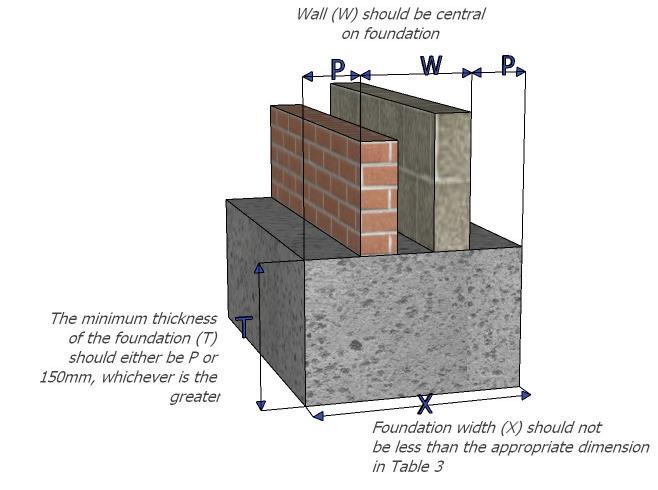
Foundation Types – Plain Concrete
Strip Foundation
Should generally be a minimum of 600mm in width, depending on the overall wall thickness, the design should take in to account the ground conditions and be in accordance with the table on P54. The foundation concrete should have a minimum thickness equal to the projection or 150mm (whichever is greater).
Trench Fill Foundation
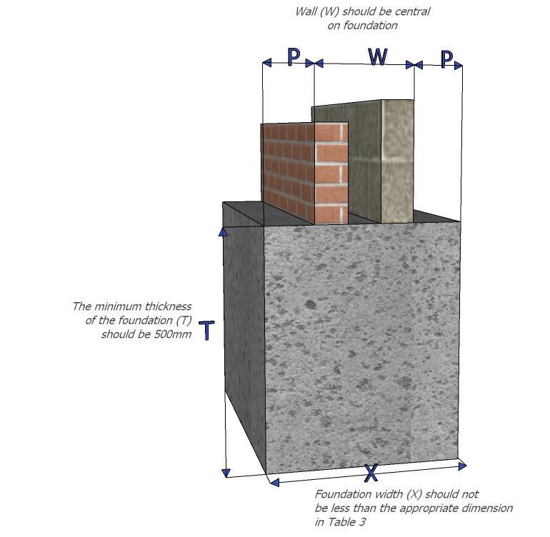
Should generally be a minimum of 450mm in width, depending on the overall wall thickness, the design should take in to account the ground conditions and be in accordance with the table 1.
The foundation concrete should have a minimum thickness of 500mm.
53
5.1
on P56
on P56
5.2 MINIMUM DEPTH OF STRIP FOUNDATIONS
Ground conditions must always be established as part of the initial site investigation, and guidance found in the requirements of Approved Document A of the Building Regulations 2013 page 5, should be followed, and relevant approvals sought.
Where ground conditions are susceptible to frost action, the foundation should have a minimum depth of 0.45m to the underside, this depth however will be subject to change in relation to loading and weather conditions at the time of excavation.
In shrinkable soils, which are subject to volume change, the Modified plasticity index must be considered when determining the minimum depth as follows:
54
Modified Plasticity Index Volume Change Potential Minimum Depth (mm) <10 Low 750 20-40 Medium 900 40-60 High 1000 >60 Very High Refer to specialist advice
5.2
5.3 CONCRETE MIX
General purpose concrete mixes should be suitable for the end use and be specified in accordance with BS 8500-1 and BS 8500-2.
55 5.3
Location for Use Site Mixed Ready Mix Consistency Strip Foundation GEN1 ST2 S3 Trench Fill Foundations GEN1 ST2 S4 Mass Concrete Foundations (others) GEN1 ST2 S4 Cavity Wall Fill GEN1 ST2 S3
56 5.3 Type of Ground (including engineered fill) Condition of Ground Field Text Applicable Total load of load-bearing walling not more than (KN/m) 20 30 40 50 60 70 Minimum width of strip foundation (mm) Rock Not inferior to sandstone, limestone or firm chalk Requires at least a pneumatic or other mechanically operated pick for excavation. Equal to the width of the wall plus 50mm each side. Gravel Sand Medium dense Requires pick for excavation. Wooden peg 50mm square in crosssection is hard to drive beyond 150mm. 250 300 400 500 600 650 Clay/Sandy Clay Stiff Can be indented slightly by thumb. 250 300 400 500 600 650 Clay/Sandy Clay Firm Thumb make impression easily. 300 350 450 600 750 850 Sand/Silty Sand/ Clayey Sand Loose Can be excavated with a space. Wooden peg 50mm square in crosssection can be easily driven. 400 600
fall
provisions of this guidance where the total load exceeds 30kN/linear m. Silt/Clay/Sand Clay/Clay or Slit Soft Finger can be pushed in up to 10mm. 450 650 Silt/Clay/Sand Clay/Clay or Silt Very soft Finger can be easily pushed in up to 25mm. Refer to specialist advice.
Does not
within the
5.4 STEPPED FOUNDATIONS
5.5 ENGINEERED FOUNDATIONS
Foundations stepped on elevation should horizontally overlap by twice the height of the step, by the thickness of the foundation, or 300mm, whichever is the greater. (see Fig. opposite).
Trench fill foundations should horizontally have an overlap of twice the height of the step or 1000mm, whichever is the greater.
Steps in foundations should not be of greater height than the thickness of the foundation. Refer to Section 2E2 of Approved Document A of the latest Building Regulations.
Ensure concrete depth is the same throughout a stepped foundation.
Ensure trench fill foundations do not have steps more than 500mm to reduce differential ground movement. Create two steps to reduce a step of more than 500m in height.
The location of the foundation joint and the joint construction must be detailed by a Structural Engineer.
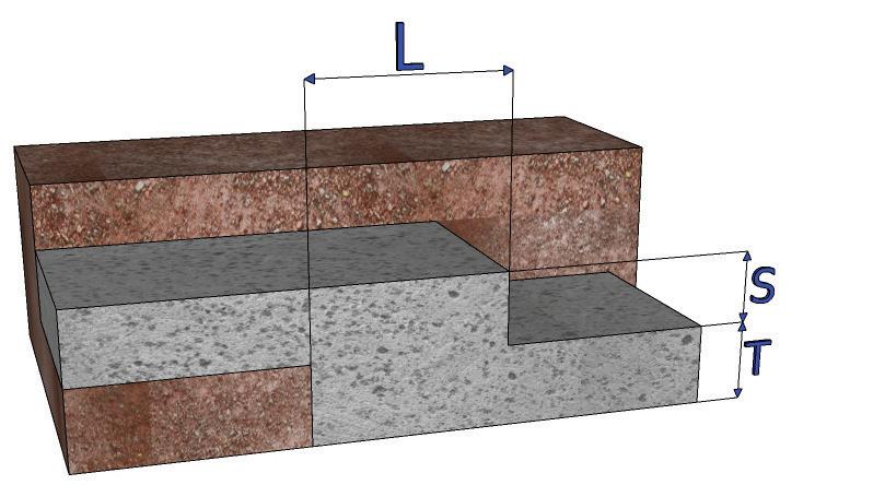
All engineered foundations such as piled and raft foundations should be designed by a suitably qualified structural engineer, the details, drawings, technical guidance, ground conditions and calculations should be made available for inspection.
5.6 ENGINEERED FILL
Any engineered fill material used for foundations should be carefully selected and have the appropriate documentation to be classed as an engineered fill.
In designing and specifying a fill which is to form a foundation, the following technical requirements should be established:
• The excavation must be well constructed, free from contaminants, areas of poor strata removed and well drained.
• Sound fill with correct material and capable of compaction, provided with starter, and should be compacted no greater than 5 times its nominal value.
57
T=MIN 150mm Minimum overlap + twice height of step or thickness of foundation or whichever is greater, S should not be greater than T For trench fill foundation minimum overlap L= twice the height of the step or 1m whichever is greater 5.4
5.7 PILED FOUNDATIONS
Pile foundations are deep foundations, formed by long, slender column elements such as steel or reinforced concrete, or sometimes, timber. A foundation may be described as ‘piled’ when its depth is more than three times its breadth.
The bearing capacity of a pile is determined by several factors, including the size, shape and type of pile, as well as the particular sub-soil properties.
Where the bearing capacity of the soil is poor and / or imposed loads are high, pile foundations are the preferred foundation support option.
There are two main types of pile design or a combination of both may also be considered. This depends upon the geology and the loads that the piles are required to support.
• End bearing piles, where the pile acts as a column carrying the load down to the bearing strata.
• Friction piles, where the load is gradually transferred along the length of the pile.
There are four prominent methods of Piling:
1. Bored piles, known also as replacement piles or drilled piles, are constructed when large holes are drilled in the ground and filled with concrete. A steel reinforcement cage is also usually incorporated and lowered into the hole before the concrete is placed or dropped in after the concrete has been poured. Bored piles are popular in urban areas when forming pile foundations close to existing buildings, as there is minimal vibration, they can be used where headroom is limited.
There are two commonly used sub-types of Bored piles:
• Rotary bored piling; used when there are potential known significant obstructions in the ground. A temporary casing is normally installed to support the pile stem, as subsoil and rock is removed from inside the casing. A reinforcement cage is then installed, and the shaft is filled with concrete and the casing removed. Where water is present in the bore the concrete should be ‘tremmied’ in place.
• Continuous Flight Auger (CFA) piling does not require the use of temporary casing as the ground
is supported by the auger itself. It is probably the most effective and commonly used type of bored pile foundation. Concrete is pumped into the bored stem mitigating the need for a tremie , and a steel reinforcement cage inserted afterwards.
2. Driven piles, with each of these materials, the piles are driven into the soil, pushing equal volumes of soil sideways and compacting a zone around the pile, increasing its bearing capacity, options include:
• Precast concrete piles; more heavily reinforced and with comparatively stronger concrete to withstand transportation loadings, driving stresses, and design imposed loads. They may be pre-stressed of square, octagonal or other cross sections. They may be driven as one full length or sections may be joined to form longer lengths. If used, the type of joint should be designed for the loadings required. The nature of the ground may determine the need to also incorporate a cast iron or steel shoe to aid driving in strong ground.
• Steel piles; tubular, box, or H section can be used for building foundations. Interlocking steel sheet piles are also utilised predominantly for wall construction.
• Timber, a technique that is centuries old. In the UK, timber piling is used mainly for coastal works, sea defence and jetties.
3. Driven and cast in-situ piles, combine the advantages of the two common piling methods. Options include, driving a permanent casing into the subsoils that may be precast concrete or steel, followed by pouring concrete into the casing forming a composite pile.
4. Aggregate piles, stone columns or vibrated columns involves compacted aggregate to form the pile stem, rather than concrete. Generally, the process involves:
• A vibrating steel mandrel is introduced to a design depth and at a predetermined spacing. Once inserted the stone is introduced and compacted in stages as the mandrel is extracted and reinserted into the ground.
58
5.7
• The aggregate is forced sideways into the surrounding soil to improve bearing capacity.
• Vibro-type aggregate piles create densely compacted columns made from gravel – or a similar material – using a vibrating casing. The displacement process densifies the surrounding granular soils.
5. Other methods of piling include:
• Screw piles utilise circular hollow galvanised steel pile shafts with one or more steel helices attached. The helix is screwed into the subsoil much like a screw is fastened into wood.
This type of pile minimises the spoil created by installation and is utilised more generally on small scale projects.
• Mini piles, sometimes referred to as micro piles, have diameters approximately ranging from 100– 400mm. In locations with restricted access smaller sized piling rigs are utilised where traditional piling rigs could not operate. Mini-piles have also many uses within the underpinning sector where foundation failures and remediation are deemed necessary. They can be driven or screwed into position.
A Structural Engineer, experienced in pile design should consider all the pile options previously mentioned. An appraisal of the proposed development/site conditions should include:
• The design loads of the proposed structure
• The findings of a minimum phase 2 ground investigation report (bore holes, trial pits etc).
• Due consideration for potential pathways set up by the installation of piles and the ‘release risk’ of any ground gases or contamination. Appropriate measures to be confirmed by the Structural Engineer to mitigate potential release of such gases and ground contamination.
• Confirmation of the required testing regime for the proposed installed piles. All of the above are particularly relevant and will provide Structural Engineers’ guidance to third party, sub-contract piling contractors which are likely to be engaged.
Why use piles
It negates the use of deep uneconomic trenches together with the safety implications of excavating such foundations:
• Deep trenches involve high excavation and cart away costs
• Deep trenches require shuttering for safety at work measures, as a result making the provision of slip membranes and heave precautions (void formers) difficult to place with confidence and accuracy • Labour savings (skilled and unskilled)
• Material savings (concrete and void formers etc.)
• Engineered piled foundations are generally more predictable and reliable.
• Their carbon footprint is generally more efficient
• Piles are particularly appropriate for heave sites (trees removed) for which they are strongly recommended. Nevertheless, such piling solutions must still be designed and installed to negate Heave.
59
5.7
5.7 TYPICAL PILE AND SUB-STRUCTURE PROFILES AND IMAGES
DRIVEN OR BORED WITH REINFORCED GROUND BEAM
MODULAR FOUNDATION
60
5.7
SCREW PILE, VIBRO PILE OR VIBRO COMPACTION
Ground beams and RC pile caps
• Precast RC beams can be installed and over-excavation beneath the beam undertaken to accommodate any potential heave – use of precast beam may be beneficial in difficult ground conditions .
• Cast in-situ beams will require provision of a minimum cover to reinforcement. (i.e.. 75mm when cast in the ground with no shuttering).
Where heave is anticipated both beams and caps will require sufficient void forming material
61
5.7
5.7 PILE DESIGN AND ADDITIONAL GUIDANCE
General minimum requirements:
Pile design should follow accepted proven design methods, in accordance with BS8004/BSEN1997 taking account of ground conditions described in the SI report and Bore hole logs. The design should confirm that the pile / pile system can support all anticipated loadings such as, compressive, tensile, lateral, heave and negative skin friction forces. Settlement of the foundation should not exceed the requirement of the structure.
• A site-specific geotechnical site investigation should be undertaken in advance of pile design and be in accordance with BS5930/EC7. The investigation should include sufficient, geotechnical testing along and beneath the pile, to enable accurate geotechnical design of the pile in accordance with accepted and proven design methods. Guidance for the requirements of a piled foundation can be found in annex A of The ICE specification for ground investigation
• Structural / geotechnical design is required to confirm individual pile lengths. For driven pile design, it is acceptable for piles to be driven to a “designed set” (in accordance with proven design methods) but this is for installation purposes. Overall acceptance will not be given without pile load testing and reference to the ground conditions and / or confirmation from the qualified professional i.e. the Independent structural design consultant, that no further pile testing is required.
• The design factor of safety should be determined by the qualified professional, such as the Chartered Structural Engineer, and take account of the reliability and extent of the site investigation, confidence in the design and hence the recommended pile load testing regime and accord and comply with BS8004/BSEN 1997
• There remains the provision not to static load test installed piles (refer to BSEN 1997) based on an enhanced set of fixed partial safety factors. Such circumstances, normally lead to a minimum FOS of 3 being utilised. If no testing is undertaken the independent structural design consultant is required to formally confirm this as acceptable, having given consideration to all of the above.
• Integrity testing must always be undertaken to all piles supporting overlying structure but this does not apply to steel, concrete driven screw piles vibro compaction (see pages 64-66)
• It is normal practice to install Piles of the same length below any individual shared RC pile cap. The qualified professional, usually a Chartered Structural Engineer needs to give serious consideration to this aspect. If this should not be the case, a Chartered Structural Engineer experienced in plie design will need to provide a full design analysis and confirmation that differential movement will not effect the structural stability and viability of the design.
• Foundation contractors and Piling specialist should confirm their membership of the Federation of Piling specialists a professional body who regularly audit and hence uphold best quality and good standards across the foundation / Piling sector.
62
5.7
There are a number of unique sub-soil profiles that may present detrimental influences on pile integrity, stability and serviceability. Some examples are listed below:
• Piling in Chalk, Reference should be made to CIRIA PR86 for CFA piles and for others C574, for pile design and installation.
• Piling where known cavities are present and / or subject to cavitation due to the presence of potential brine dissolution and gypsum dissolution. Some form of redundancy should be considered at design stage to counter unknowns.
• Piling over / adjacent mine workings. Reference should be made to CIRIA SP32 / C758D Piling adjacent to mine shafts should ensure that adequate competent rock is available, that rock sockets are achieved and that piles won’t be affected by a potential partial / future collapse of the shaft.
Pile foundations should always be designed by a qualified professional such as a Chartered structural engineer / geotechnical engineer with experience in designing piled foundations and should include the following criteria:
• Design to length for bored piles (or set for driven piles where these are recommended following ground investigations)
• Precautions to resist tensile uplift and heave
• Provision of sleeving to top section
• Preference is for installing longer piles designed to balance uplift
• Tension reinforcement required
Pile layouts can be readily designed to accommodate an individual plot. A good design will seek to achieve cost savings in foundation excavation and materials by the incorporation of large ground beam spans between piles, and a small number of piles.
Floor construction:
• Suspended floors with provision for adequate ventilation
• Beam and block or hollowcore precast floor units may be better than timber flooring to accommodate large spans designed for economies
Ground beams and RC pile caps
• Precast RC beams can be installed and overexcavation beneath the beam undertaken to accommodate any potential heave – use of precast beam may be beneficial in difficult ground conditions
• Cast in-situ beams will require provision of void formers and a minimum cover to reinforcement (i.e.. 75mm when cast in the ground with no shuttering)
63
5.7
Pile construction records
Normally referred to as ‘Pile Logs’, pile construction records should be made available for all piles installed. The records should include the following information:
• Pile type (driven tube, Continuous Flight Auger (CFA), auger bored etc.).
• Pile dimensions (diameter or width / breadth).
• Pile depth.
• Driving records from driven piles– including hammer type, weight, drop height, sets, hammer efficiency.
• Pile verticality confirmation– this should not be more than 1:75 from vertical.
• Also no more than 75mm horizontal distance from the designed pile position
• For CFA and concrete screw piles, we should be given the computer output for concrete volume and rig. Performance– view a typical CFA output for a well-constructed pile.
• A cross referenced piling layout plan.
• Where wet concrete is installed in the ground (cast in situ piles) Cross referenced Concrete cube samples and testing for insitu concrete, must be undertaken and be representative of the whole piling installation and formally acknowledged / deemed as acceptable by the Qualified design professional.
• Piling information and records should be in accordance with “SPERWALL”.
Pile Testing
Piled foundations should be tested to ensure that they meet the structural design requirements.
Pile testing confirms and validates that the piled foundations are indeed capable of supporting the independent structural design consultants specified loadings, that are transferred from the superstructure, as well as providing quality assurance. A pile testing plan should always be specified at design stage and should take account of the complexity of the piling system envisaged. Further guidance is available from The Federation of Piling Specialists who have produced the ‘Federation of Piling Specialists Handbook on Pile Load Testing.’
Methods of testing and design consultants’ approval
The Independent Structural design consultants should specify individual Pile loads determined from the superstructure design, having given consideration to sub-soil testing, ground improvement, load-bearing characteristics and settlement potential.
Additionally, a specification for pile testing shall be required that conforms to accepted industry standards and codes of practice and thereafter confirm as satisfactory, the Pile testing regime undertaken and test results outcome. SPERWALL will provide further advice on such items.
• Static load testing:
Preliminary pile tests are recommended particularly on larger schemes: The test involves applying / maintaining static loads in accordance with BS 8004, SPERW, or other accepted standards; This test is normally carried out before work starts on site or at the very beginning of a project.
• Working pile tests:
Also Involves applying / maintaining static loads in accordance with BS 8004, SPERW, or other accepted standards. Working load testing is to be carried out at a rate of 1 per 100 piles or part thereof (not less than 1%). However additional tests may be required on sites with more unstable ground or where workmanship has been an issue, but necessarily as agreed and specified by the independent Structural design consultants.
Where there are large variations in substrata revealed either by the site investigation or during the construction of piles, load tests should be carried out in each zone and the level of testing reassessed accordingly for each design situation. Similarly, load testing should reflect the various pile lengths and loadings.
64
5.7
• Dynamic load testing:
Dynamic tests also known as large strain testing; this technique is most commonly used for assessing the dynamic pile capacity of driven piles and is a method to assess a pile’s bearing capacity by applying a dynamic load to the pile head (a falling mass) while recording acceleration and strain on the pile head. The test is required to utilise analysis software such as CAPWAP/ SIMBAT and must be evidenced.
Dynamic testing should be undertaken to reflect the detail of the site investigation report, the ground conditions and the factor of safety adopted in pile design. Dynamic load testing should be viewed with caution in fine grained soils. Any variation from the anticipated pile length or performance highlighted by dynamic testing should be verified by further site investigation and subsequent design or maintained load testing.
For dynamic tests on driven piles to determine the dynamic pile capacity, a minimum number of 1 test or 3% of the working piles should be sought, whichever is the greater. Further tests may be required if anomalous results are obtained.
• Integrity testing also known as low strain testing is undertaken to test the integrity of each installed pile, and potentially reveal the presence of defects, anomalies and discontinuities within the pile stem. There are two types of tests which are used solely for assessing pile integrity:
• Cross hole sonic logging, generally carried out on piles over 750mm diameter.
• Pulse echo.
For integrity testing of bored and Continuous Flight Auger piles, 100% of the piles should be tested.
• Negative skin friction; where piles pass through ground that may consolidate or change in volume (e.g. due to a change in water table or loading due to raising of levels) the effects of negative skin friction should be taken into account. The capacity of the pile to resist the additional compressive and tensile stresses beyond that imposed by the structure should be checked at critical cross sections.
Recorded information required for sign off
ICW require the following documentation as a minimum:
• Geotechnical report.
• Independent design consultants piling specification, loadings and proposed testing regime.
• Specialist piling contractors design, calculations and pile layouts.
• The pile logs, including all alterations / variations to pile installation or design. Including all documentation associated with QA / control.
• Formal approval, by the Independent design consultants, of the Pile design and installation, including confirmation that the Pile test regime/ results and other associated items such as concrete cube test results, are satisfactory with regard to structural stability, integrity and future serviceability. In the absence of all of the above formal approvals, by the Independent design consultants, a co-lateral Warranty insurance will be required for the same above items.
65
5.7
Piling
Driven Precast
Driven steel encased
Bored cast in-situ
Screw piling
Vibrated stone columns (VSC) / ground improvement
Key: Required ?
Not required
Geotechnical report
Structural Engineer design*
Specialist piling contractors design**
Pile log Load test Integrity test Engineers sign off ?
Raise further enquiry and seek confirmation from client’s structural engineer if this type of testing is required/specified.
Note:
*Structural engineer’s design, specification and calculations package for foundations / sub-structure.
**Specialist piling contractors design, specification and calculations package for piling.
There may be clarifications and queries that you may wish to discuss regarding any of the above advice, hence do not hesitate to contact ICW.
This is particularly important if there are potential deviations with Design. Discussions and prior agreement to commencement will benefit all.
66
? ? ? ?
5.7
5.8 RAFT FOUNDATION
A raft foundation consists of a raft of reinforced concrete under the whole of a building. This type of foundation is described as a raft in the sense that the concrete raft is cast on the surface of the ground which supports it, the foundation is not fixed by foundations carried down into the subsoil.
Raft foundations may be used for buildings on compressible ground such as very soft clay, alluvial deposits and compressible fill material where strip, pad or pile foundations would not provide a stable foundation without excessive excavation. The reinforced concrete raft is designed to transmit the whole load of the building from the raft to the ground where the small spread loads will cause little if any appreciable settlement.
When the option of a raft foundation has been chosen this must be designed by a suitably qualified engineer and the design must be available for inspection. Reinforcement must be installed and supported as per the design.
67
Volume Change Potential Low Medium High Void dimension against side of foundation and ground beam 0mm 25mm 35mm Void dimension under ground beams and suspended in-situ concrete ground floor 50mm 100mm 150mm Void dimension under suspended precast concrete and timber floors 200mm 250mm 300mm
5.8
5.9 FOUNDATION AND TREES
If trees are within the area of influence of the proposed foundations, appropriate measures must be taken to counter the potential effect of changes in ground conditions in shrinkable clay soils i.e. heave. This is relevant to any tree regardless of size and maturity. Foundations affected by trees with a depth of more than 1.5m should be provided with protection from heave in the form of a compressible material, which should be installed to the inside surface of the foundation. The compressible material should be placed 500mm above the bottom of the foundation. It is recommended that manufacturers installation guide is utilised. Heave precautions should be placed to all elevations of the internal face of foundations.
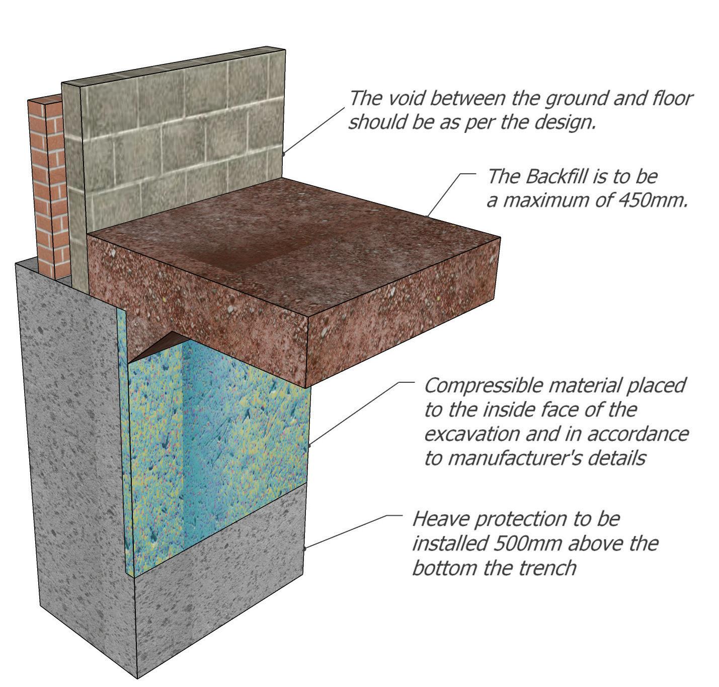
*ER: Engineered required
68 5.9
Water Demand Tree/height (m) Soil Volume Change Distance to Tree (m) 2 5 10 15 20 25 30 35 High water demand Broad-Leaf Hawthorn (10m) High ER 2.5 1.5 1 1 1 1 1 Medium ER 2.5 1.35 1 0.9 0.9 0.9 0.9 Low 2.25 1.8 1.1 1 0.75 0.75 0.75 0.75 Weeping Willow (16)m High ER ER 2.25 1.65 1 1 1 1 Medium ER 2.5 1.95 1.45 0.9 0.9 0.9 0.9 Low 2.35 2.1 1.65 1.2 0.75 0.75 0.75 0.75 English oak (20m) High ER ER 2,5 2 1.5 1 1 1 Medium ER ER 2.2 1.75 1.35 0.9 0.9 0.9 Low 2.4 2.25 1.8 1.45 1.1 0.75 0.75 0.75 English Elm (24m) High ER ER ER 2.25 1.85 1.45 1 1 Medium ER ER 2.3 1.95 1.6 1.25 0.9 0.9 Low 2.4 2.25 1.95 1.65 1.35 1.05 0.75 0.75
69 5.9 Water Demand Tree/height (m) Soil Volume Change Distance to Tree (m) 2 5 10 15 20 25 30 35 High water demand Coniferous Leyland Cypress (20m) High ER ER 2.5 2 1.5 1 1 1 Medium ER 2.15 1.25 0.9 0.9 0.9 0.9 0.9 Low 2.25 1.8 1.05 0.75 0.75 0.75 0.75 0.75 Moderate water demand Broad-Leaf Apple/Plum/Pear (10m) High 2.1 1.65 1 1 1 1 1 1 Medium 1.8 1.4 1 0.9 0.9 0.9 0.9 0.9 Low 1.45 1.15 0.75 0.75 0.75 0.75 0.75 0.75 Alder/maple/ Walnut (18m) High 2.2 1.9 1.4 1 1 1 1 1 Medium 1.85 1.6 1.2 1 0.9 0.9 0.9 0.9 Low 1.5 1.3 1 0.75 0.75 0.75 0.75 0.75 Beech/Horse Chestnut/ Sycamore (2024m) High 2.25 2.05 1.65 1.25 1 1 1 1 Medium 1.9 1.7 1.4 1 0.9 0.9 0.9 0.9 Low 1.5 1.3 1 0.75 0.75 0.75 0.75 0.75 Moderate water demand Coniferous Pine/Larch/Spruce (18-24m) High 2 1.4 1 1.25 1 1 1 1 Medium 1.7 1.25 1 0.9 0.9 0.9 0.9 0.9 Low 1.4 1 0.75 0.75 0.75 0.75 0.75 0.75 Low water demand Broad-Leaf Fig/Hazel/Elder (8-10m) High 1.5 1 1 1 1 1 1 1 Medium 1.3 0.9 0.9 0.9 0.9 0.9 0.9 0.9 Low 1.05 0.75 0.75 0.75 0.75 0.75 0.75 0.75 Holly/Laburnum/ Birch (12-14m) High 1.6 1.25 1 1 1 1 1 1 Medium 1.35 1.1 1 0.9 0.9 0.9 0.9 0.9 Low 1.1 0.9 0.75 0.75 0.75 0.75 0.75 0.75
5.10 CONSTRUCTION
PRINCIPLES
Strip/Trench Fill Foundation
• Setting out is true and accurate to the design.
• Excavations have been formed neatly with welltrimmed sides and bottom.
• Minimum depths have been calculated and achieved.
• Minimum widths have been calculated and achieved.
• Steps have been formed correctly.
• Soft spots have been removed or designed out.
• Where reinforcement is required it is installed as per the design.
• Excavations are clean with no loose debris or water present.
• Heave protection installed as per design (if required) Piled foundation .
• Pile log is onsite and ready for inspection.
• All piles are in the correct locations.
• Alignment and spacing is accurate.
• No visible damage to piles.
• Excavations more than 2.5m in depth must be designed by a structural engineer.
Raft Foundation
• Setting out is true and accurate to the design.
• Excavations have been correctly formed.
• Correct diameter reinforcement has been used.
• Reinforcement is correctly installed with spacers.
• Laps to reinforcement have been tied as per the design.
• Excavations are clean with no loose debris or water present.
• Rafts are not considered as an acceptable method of foundation where the ground conditions are susceptible to heave or shrinkage.
• Ratio must not be more than 2:1
• The design must state the maximum the raft can be formed / constructed.
• The toe underside is a minimum 600mm from the external finished floor level.
• Services must not be situated with the toe of the raft unless approved by the raft designer.
• The hardcore / infill should not be less than 50% of the foundation depth and should not exceed in depth 1.25m from underside of the raft slab element.
• Compacted hardcore depth, compaction rate and layers to be included in raft design.
Raft Slab Element:
• Minimum 150mm in thickness / depth.
• Minimum 25mm cover above slab reinforcement.
• Minimum 450mm overlap on reinforcement.
70 5.10
71 5.10
72
SUBSTRUCTURE
73
6.0
6.0 SUBSTRUCTURE
Statutory Requirements
Roles and Responsibilities
When considering the substructure, the design should be linked directly to the site investigation report. It is the responsibility of the developer to ensure the correct substructure is provided and inspected.
Building Regulation Requirements
The requirements of the Approved Documents of the Building Regulations 2013 should be followed, at all times and all of the relevant approvals sought from the Building Control Body.
If any calculations are required to support the proposed design, then these should be provided by a suitably competent and qualified person. The calculations will need to be designed so as they safely distribute loads and forces to the foundations.
Workmanship
During the construction phase:
• All workmanship must be completed in a competent workmanship like manner.
• Protected against unnecessary damage.
• Design and Installation specifications are followed.
• Products and materials are inspected for suitability for their purpose.
Materials
All materials used shall:
• Be adequately protected and stored in a correct manner.
• Comply with relevant British Standards or equivalent European Technical Specification with the certification available for inspection by ICW.
• Be installed as per Manufacturers details.
• Have a life span of 60 years when used as part of the structure. However it is accepted that materials that are not an integral part of the structure may require maintenance and or replacement within this period.
Design
Where a specialist design is requested or required, they shall:
• Be designed by a suitably qualified person.
• Be supplied with clear precise instructions.
• Be supported with structural calculation when outside the guidance of the Approved Documents.
• Be available for inspection by ICW.
74
6.0
6.1 WALLS BELOW DPC
Bricks and Blocks
Sulphate Attack
In saturated brick work soluble salts from certain types of bricks may cause a chemical reaction with a constituent of the Portland cement in the mortar. The surface of the mortar joint will crack, and the inside will crumble and expand, disrupting the brickwork.
It is acceptable to use bricks and blocks below DPC where there is no soil borne sulphates present. If sulphates are present then the suitability of the materials should be checked with the supplier/manufacturer.
75
6.1
6.2 DAMP PROOF COURSE
DPMs should be designed to meet the requirements of BS EN 13707 or CE Mark to EN 13967 and be a flexible material laid on mortar and lapped at corners and junctions a minimum of 100mm. DPC’s should link to damp proof membranes.
Installed DPC’S should be:
• 150mm above finished ground level.
• Link with the DPM.
• The correct width.
• Fully bedded.
• Lapped by 100mm.
When installing a continuous tray, the tray should be:
• 150mm above finished ground level.
• Have an upstand of 150mm.
• Have a slight projection.
• Fully bedded.
• Lapped by 100mm.
• Link with the DPM.
• Have weep holes placed at 900mm centres.
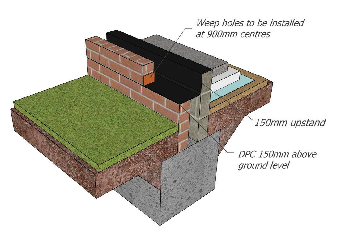
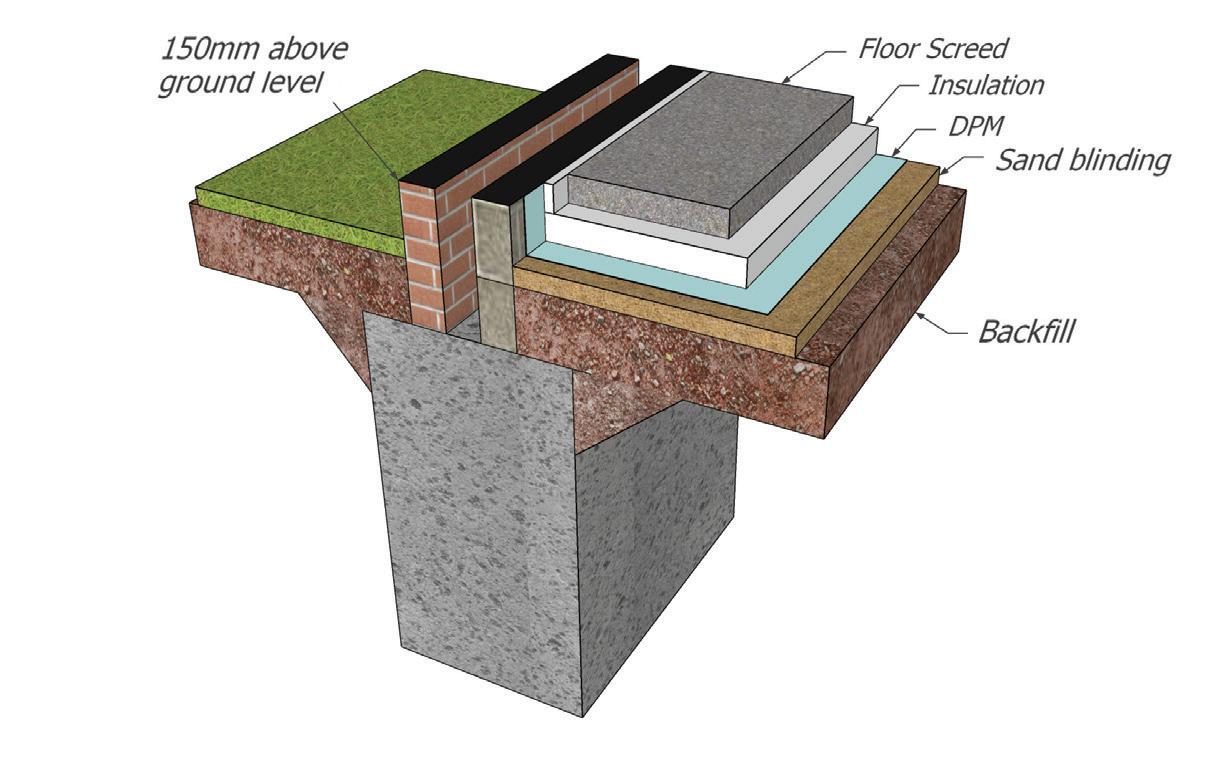
Acceptable materials for use as DPCs
Bitumen Based Material
Polythene
Propriety Materials
BS 6398
BS 6515 (min thickness 0.5mm)
With manufacturer’s details
76
6.2
6.3 SERVICE PENETRATIONS
6.5 PIPES LINTELLED THROUGH WALLS
Any penetrations through the substructure should have been designed and details should be available for inspection, all services should be sleeved where they pass through the structure for future access and maintenance can be carried out.
Where drains penetrate the structure there are several recognised methods acceptable.
6.4 PIPES BEDDED INTO WALLS
Flexible joints are to be installed as per the diagram and set no more than the maximum dimensions given, it is accepted that the second flexible joint may be an inspection chamber.
Sleeve should have a 100mm larger diameter to allow for a clear 50mm movement gap, the ends of the sleeves should be masked on both sides to prevent rodent entry.
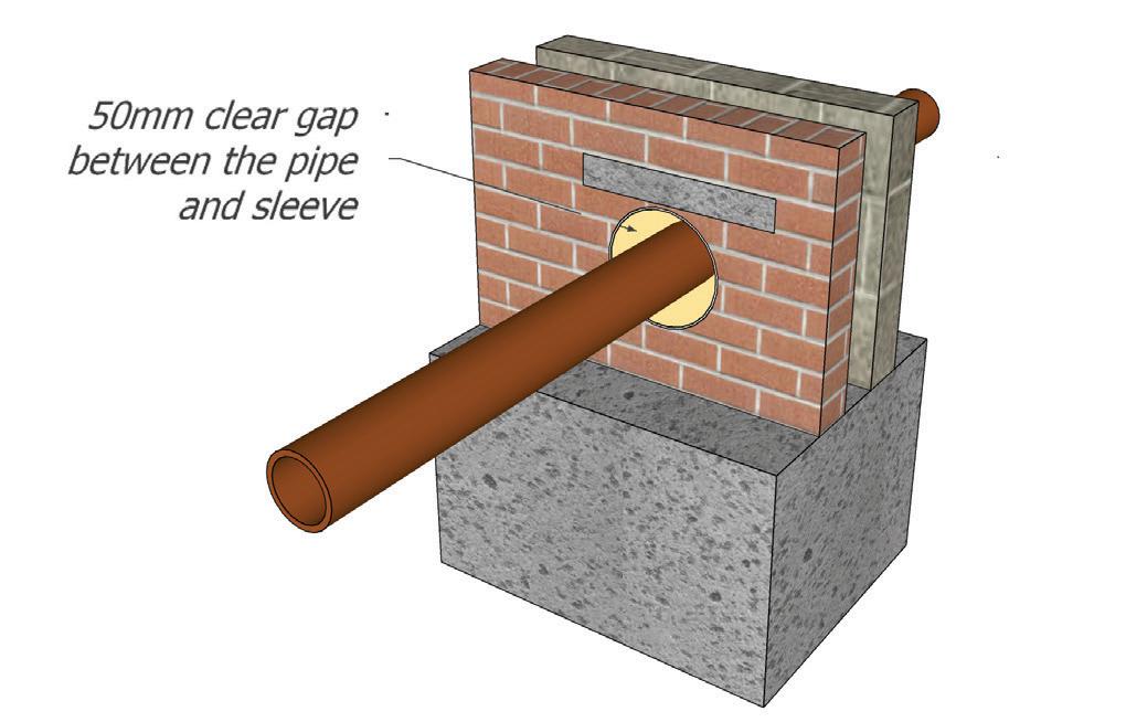
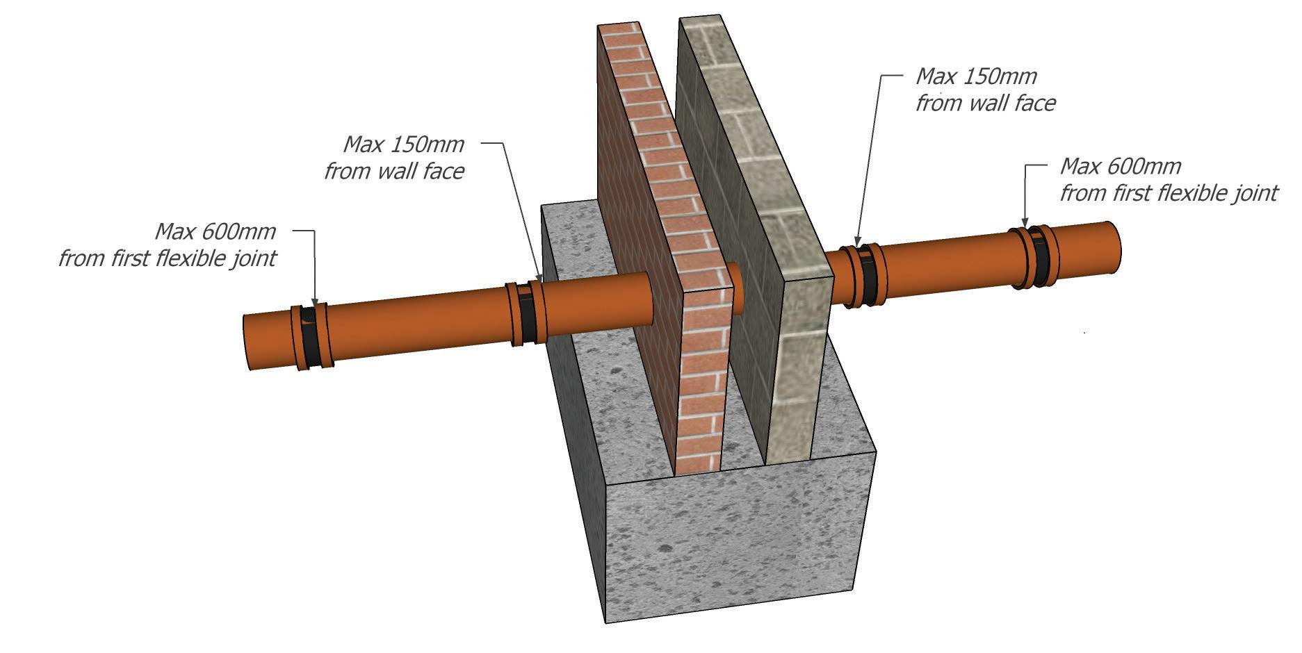
77
6.3
6.6
BASEMENTS
INTRODUCTION
When considering waterproofing the scheme should be designed and constructed in accordance with BS 8102: 2022 “Protection of Below Ground Structures Against Water Ingress” and BS EN 1992 parts 1-3.
78
6.7
It is recommended that during design stage and all stages of the process, designers, manufacturers and suppliers of waterproofing products are involved. It is necessary to appoint a waterproofing expert at an early stage. Designers, suitably experienced, should have a suitable qualification such as the Certificated Surveyor in Structural Waterproofing (CSSW) or similar which should be agreed with ICW prior to commencement of works.
The designer must also hold sufficient professional indemnity insurance for the project.
ICW recommend that basement waterproofing is provided with contractors’ installation and material guarantees supported by an Insurance Backed Guarantee.
It should also be noted that ICW are currently unable to offer their warranty for Insulated Concrete Formwork (ICF) basement constructions.
When considering a basement or below ground waterproofing, the following process should be followed:
Sections in this zone can be approached as one stage
79
Design Team & Responsibilty Confirmed Selection of Waterproofing types Level of RiskHigh, Variable or Low High Variable/Low Desk Study, Risk Assessment & Structural Considerations Waterproofing Design Strategy Proposed Has continuity been confirmed? Has repairability been addressed and system maintainable? No Yes Yes Confirmation Contractor & Supplier Guarantees are Insurance Backed (IBG) Yes Design Confirmed and Accepted Installation on Site by approved installer Handover of all final documentation and guarantees
Site Investigation
Before starting any design or construction work, a site investigation should be carried out to establish the ground conditions (including type of subsoil), the level of the water table (including provision for natural drainage) and risk of flooding; the location of any existing drains or other services, the presence of contaminants and whether there is a risk from radon or other gases.
Contaminants
If the site investigation indicates the presence in the ground of solid or liquid contaminants, natural gases (e.g. radon) or landfill gases, then appropriate measures should be taken to limit their effect on the basement and on the remainder of the dwelling.
Underground Services and Drainage
With the agreement of the appropriate statutory authority, any services which are affected by the construction work should be re-routed around the building, or the building and the services should be designed to enable the services to run under the building, again with statutory authority agreement. The building should be oriented and designed to avoid the risk of increasing hydrostatic pressure. Where this is not practical, the waterproofing system should be designed to withstand a full hydrostatic head. Provision should be made for maintainable subground drainage (i.e. land drain) to control or maintain the external environment for which the waterproofing system was designed.
Exclusion of Moisture
Walls and floors below external ground level and the junctions between them should:
• Provide resistance to ground moisture reaching the internal surface of the wall or upper surface of the floor so that the environmental conditions in the basement are appropriate to the intended use
• Not be adversely affected by moisture from the ground.
80 6.6
Key levels of protection
(As described in BS 8102: 2022:)
1b
Performance definition
SeepageB) and damp areasC) from internal and external sources are tolerable, where this does not impact on the proposed use of below ground structure.
No seepage.B) Damp areasC) from internal and external sources are tolerable,
No seepageB) is acceptable. Damp areasC) as a result of internal air moisture / condensation are tolerable. Measures might be required to manage water vapour condensation.D) E)
No water ingress or damp areasC) is acceptable. Ventilation, dehumidification or air conditioning necessary; appropriate to the intended use.D) E)
Grade 2 is the minimum requirement for a habitable area however dependent on the intended use this may need to be Grade 3.
A) The agreed grade should meet with the client’s expectations for the intended use of the below ground space. Reducing the grade could increase the risk of not meeting the expectationsof the client for the intended use of the below ground space.
B) Seepage (sometimes referred to as weeping)is defined as in 3.14. If there is seepage, there is a possibility of mineral deposits forming.
C) Damp is defined as in 3.4
D) The scope of this document is limited to detailing the processes and best practices that can be followed when creating a waterproof or water resistant structure below ground. The additional considerations that are required to achieve the required environment are beyond the scope of this document.
E) See BS 5454 for recommendations for the storage and exhibition of archival documents.
81 6.6
Table 2 - Waterproofing Protection Grades of performance for below ground spaces
Grade A)
1a 2 3
GENERAL
Suitable waterproofing systems include mastic asphalt, combined bitumen/polythene membranes and proprietary tanking systems possessing independent third party accreditation acceptable to ICW. All tanking systems should be installed in accordance with the manufacture’s instructions.
SHEET MATERIALS SUCH AS POLYTHENE ARE NOT DEEMED SUITABLE FOR BELOW GROUND WATERPROOFING.
TYPE A
(Barrier Protection)
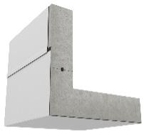
Externally applied fullybonded sheet membrane

Internally applied cementbased slurry or multi-coat waterproofing render.
Tanking should be designed to resist mechanical damage and the effects of hydrostatic pressure. The below ground waterproofing system can be provided to the internal (a loading coat should be provided to prevent accidental damage to the waterproofing membrane) or external face of the basement wall itself can be designed to resist the passage of moisture and forces applied.
TYPE B
(Structurally Integral Protection)
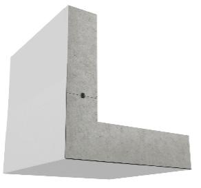
Concrete wall with hydrophilic movement Joint or other manufactured joining system.
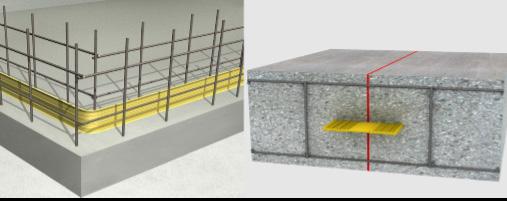
Roll of hydrophilic strip, proprietary metal or pvc water bar system.
TYPE C
(Drained Protection)
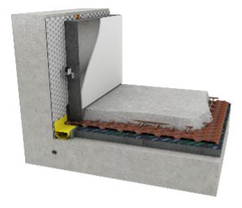
Cavity drainage membranes to internal faces of structure with maintainable perimeter drainage channel leading to sump & pump station or to daylight/safe external surface water drainage if conditions allow.
82
6.6
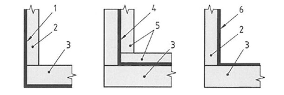
External waterproofing
Masonry or concrete wall, as appropriate
Concrete floor slab
Sandwiched waterproofing (now omitted from Standard BS8102:2022)
Loading coat (now omitted from Standard BS8102:2022)
Internal waterproofing
As before stated all basements are to be designed by an appropriate expert and be structurally stable (BS EN 1992, Parts 1-3) and resist the passage of moisture. A high level of workmanship and site supervision is essential particularly when incorporating a reinforced concrete design.
Whichever system or design is proposed, it is essential that the specification and/or the manufacturer’s details
shall be forwarded to ICW prior to commencement and preferably at design stage, for approval. It is an ICW recommendation that basement waterproofing is provided with contractors’ installation and material guarantees, supported by an IBG.
83
Omission of Sandwiched Waterproofing from BS8102:2022
1 2 3 4 5 6 6.6
FULLY BONDED INTERNALLY APPLIED WATERPROOFING TO CONCRETE SLAB TO KICKER JOINT
Internally-applied fully bonded cement-based crystalline slurry or multi-coat waterproofing render applied to the internal (negative) face of the structure and designed to resist hydrostatic pressure passing through the structure. The slurry penetrates the pores of the substrate to become monolithic and integral with it.
FULLY BONDED EXTERNALLY APPLIED MEMBRANE
Fully-bonded membrane applied to substrate/shuttering prior to concrete pour. Ensure appropriate level of protection to manufacturer’s requirements.
84
6.6
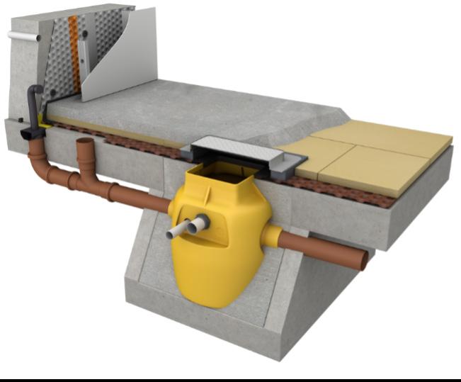
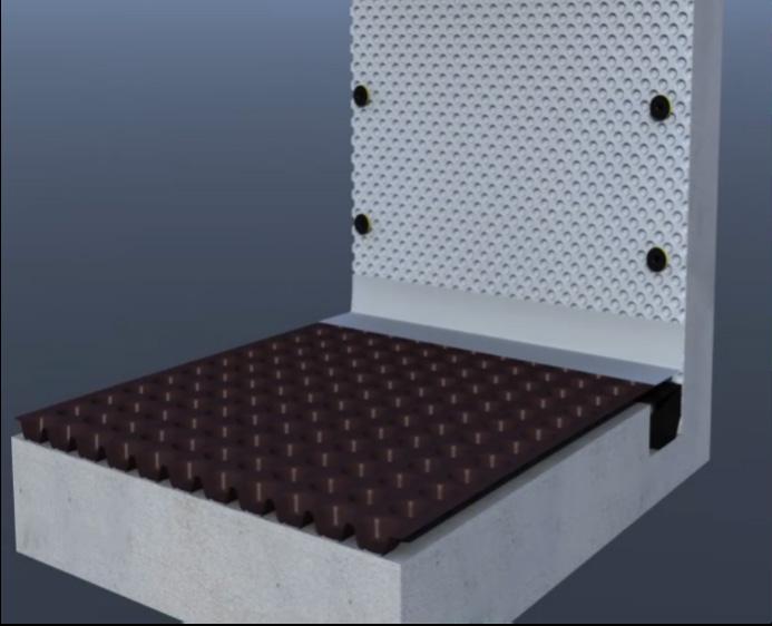
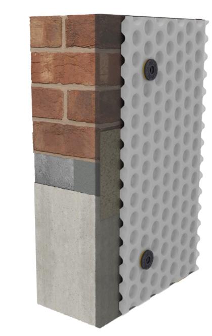
85 T Pieces End Caps Drainage Channel Without Upstand Straight Connectors Corner Pieces 110mm Outlet Drainage Channel With Upstand Access Port Unit Jetting Ports WWW.DELTAMEMBRANES.COM 4 6.6
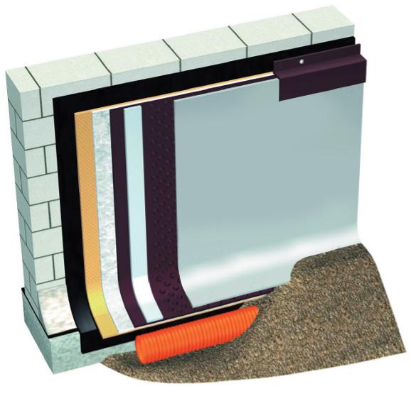
A maintainable land drain should be provided, where possible, around the perimeter of the basement at low level and the side of the basement back filled with granular material.
The following criteria should be considered in the selection of the waterproofing system to be adopted:
• Establish the position of the water table with respect to the underside of the lowest slab level according to the classification as follows:
HIGH – the water table is above the underside of the lowest slab level of the proposed basement (where because there is insufficient permeability of the soil, percolating water is held above the underside of the lowest slab level, resulting in hydrostatic pressure).
LOW – the water table is permanently below the underside or the lowest slab level.
VARIABLE – the water table varies between HIGH and LOW described above. The duration of this condition will dictate design requirements.
86
6.6
• Establish the drainage capabilities of the soil via soil analysis.
• Choose a suitable construction method to meet the waterproofing requirements.
• Consider the type of foundation and its suitability for providing continuous waterproofing structure.
• Establish the most suitable form of tanking system to suit the ground conditions. In considering which system it is important to take account of any aggressive materials found in the soil or ground moisture. All systems whether cementitious, a liquid applied or bitumen sheet membrane should have third party accreditation acceptable to ICW and be installed in accordance with the manufactures instructions by an approved installer.
• The designer of a basement must ensure all necessary details (amongst others service penetrations; change in level or direction; window/ door reveals etc.) are shown.
• A high level of workmanship and supervision is essential for all waterproofing systems.
• A waterproofing system needs to be continuous and integrated with the DPC in the superstructure. Once the type of wall construction has been established consideration must be given to detailing particularly to that of the continuity of the damp proofing system. Waterproofing to basements should be properly connected to and made continuous with wall DPCs.
87
6.6
Linking external waterproofing with dpc/cavity tray
Ventilation to Basements
• It is advisable to provide ventilation to all basements (heated or unheated) so that any moisture vapour either generated within the dwelling or brought in through the structure is adequately controlled.
• Habitable rooms including kitchens, utility rooms, bathrooms and non-habitable rooms (such as storerooms and workshops) located within a basement should meet the requirements of Approved Document F.
Drainage and Service Penetrations
All penetrations through a basement wall or tanking membrane e.g. service entry points should be avoided wherever possible. Where it is necessary to penetrate the basement wall or membrane then they need to be correctly detailed by the appointed waterproofing expert.
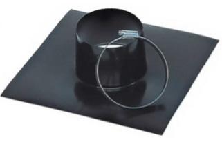
All pipework and drainage within a basement should comply with the requirements of BS EN 752. Wherever possible the soil and vent pipe (SVP), serving the dwelling should be located externally even where there are drainage connections within the basement. However, the system must be designed to reduce waterproofing penetrations to a minimum. The use of proprietary mini pumped systems can be adopted to overcome the need for such service penetrations.
Large-diameter sleeving pipe with puddle flange encapsulated within cast in-situ. Smaller diameter pipes and cables encapsulated in specialist waterproof sealing paste and pointed in using slightly-expanding repair mortar. Sleeving pipe sealed to face of internal cavity drainage membrane using wide-profile butyl tape.
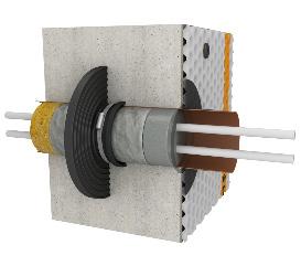
88
6.6
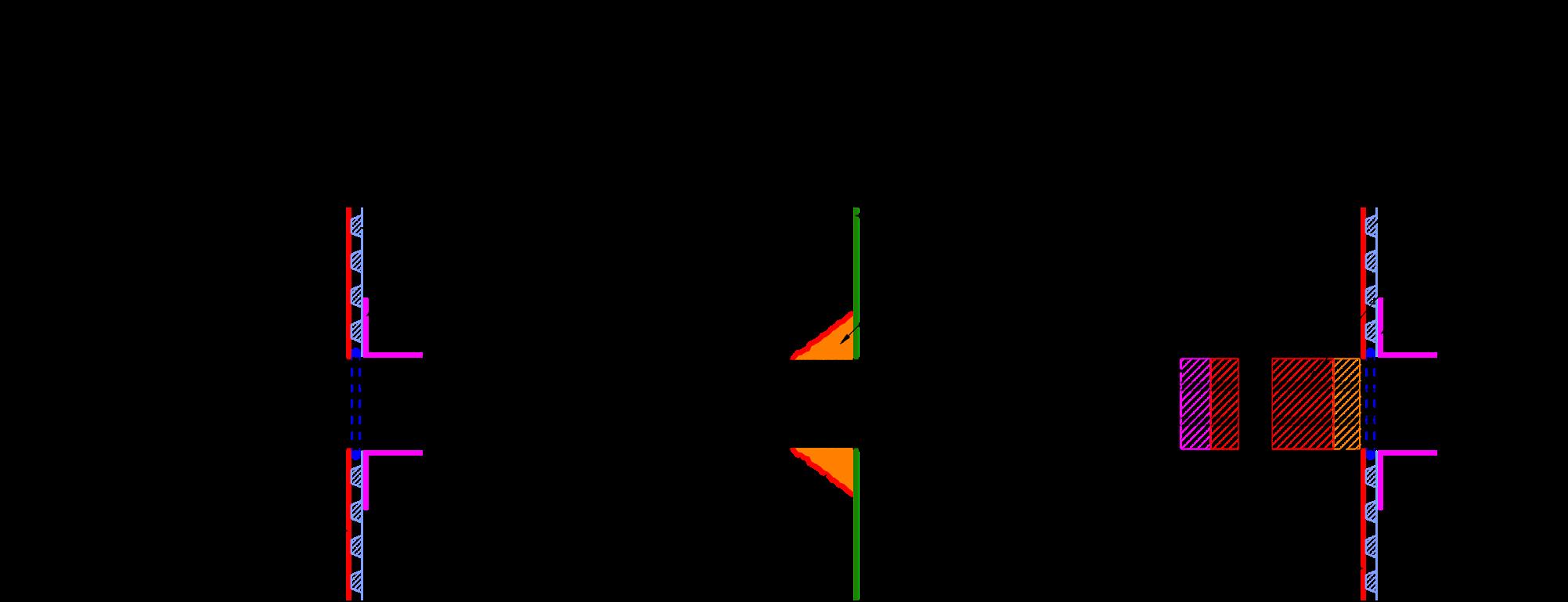
Where the pipe penetration needs to be sealed to external waterproofing, to a bonded self-adhesive sheet membrane for example, then pre-formed “top hat” profiles may be used to facilitate this, in accordance with manufacturer’s instructions.
Where service penetrations through basement walls cannot be avoided by design and /or layout, they should be designed in accordance with manufacture’s details (i.e. use of puddle flanges, water stops etc).
Where drainage connections pass through the basement wall, allowance should be given to future movement, provide a rocker pipe having a maximum length of 600mm, positioned not more than 150mm from the external face of the basement wall.
All other service entries should be designed to allow tolerance for movement of the ground and/or the
structure. It may be necessary to consult with statutory supply authorities for suitable tolerances.
Surface water drainage should comply with Approved Document H.
Access areas of basement level and lightwells to windows should be provided with suitable surface water drainage to prevent flooding.
Movement Joints
Movement joints in basement construction should be avoided wherever possible. However, where they are required, then they should be designed by a basement design expert in conjunction with manufacturer’s instructions.
89
6.6
6.7
PODIUM DECKS
INTRODUCTION
Podium decks are an open spaced amenity structural slab and/or deck designed to increase usable space, whilst helping manage the conveyance and reuse of rainwater. Used in conjunction with vegetation, they can contribute to creating amenity; rooftop bars and cafés, green areas above car parks and so on.
90
6.7
PODIUM DECK - TRANSFER DECK
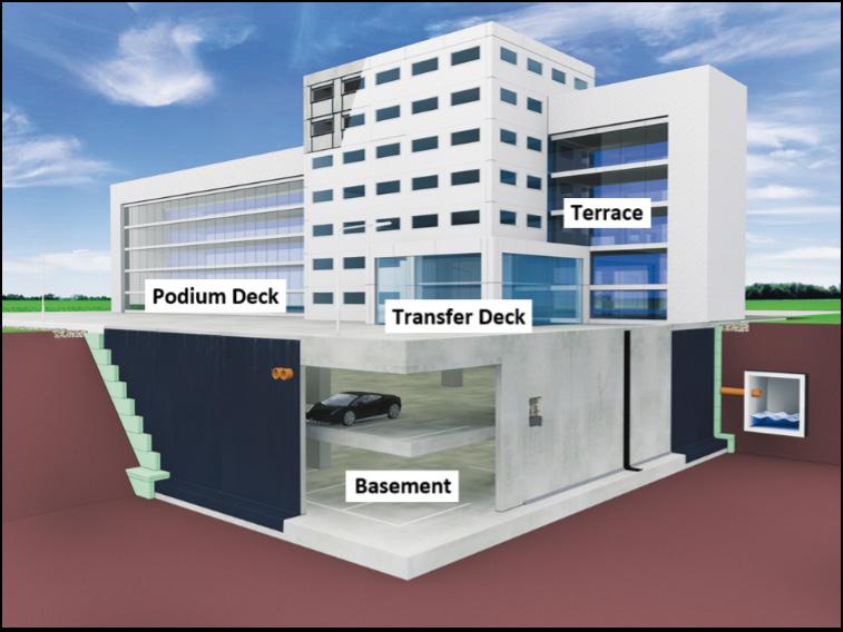
Waterproofing these versatile structures takes an in-depth knowledge of construction context and ground conditions.
Designers will approach a deck laid above a car park or non-habitable area very differently to one above a habitable space of a home:
• An externally weathered deck over an unconditioned space i.e. a carpark or non-habitable area. The requirement for waterproofing is to:
- Protect the deck surface from accumulation of water
- Prevent the ingress of water to the space below.
- Prevent ingress of water to the adjacent building.
• Where the space below the deck is a habitable space and is provided with heat and ventilation to condition the area; the deck is no longer considered a podium but instead is treated as an insulated flat roof.
91 6.7
General
If the space under the podium deck is below ground, then an expert in basement waterproofing i.e. CSSW qualified is to be appointed at an early stage in the design process..
It is an ICW recommendation that waterproofing to podium decks as per flat roofs are provided with contractors and manufacturers’ guarantees supported by an Insurance Backed Guarantee (IBG).
Substrate
For warranty purposes, beam and block and precast concrete floor planks should be avoided unless suitable waterproofing has been designed to accommodate the additional movement or risk from this type of substrate. Reinforced concrete is acceptable to ICW provided it has been designed by a structural engineer to BS EN 1992.
Other forms of construction may be appropriate for ICW warranty purposes provided that the dimensional stability can be proved. Such methods include pre-cast hollow planks with a structural screed and ribbed metal deck formwork. However, dimensional stability will need to proven by a structural engineer in conjunction with the specialist.
Waterproofing materials
Suitable waterproofing for podium decks are fully bonded systems that prevent tracking of water under the waterproofing layer. All waterproofing systems must possess independent, third-party accreditation
acceptable to ICW. All systems, should be installed in accordance with the manufacturer’s instructions and be provided with contractors and manufacturers’ guarantees supported by an Insurance Backed Guarantee (IBG).
Deck Falls and drainage
Falls are similar to flat roofs in that the falls will be generally 1:80 or in accordance with the manufacturer’s recommendations of the waterproof membrane.
Drainage should be sufficient to avoid a build-up of water on the deck. A complete drainage system should be designed by a specialist engineer along with drainage calculations to prove the design. The design needs also to be in accordance with the manufacturer’s recommendations for the intended waterproofing membrane.
Rainwater outlets should be:
• Located in areas of maximum deck deflection
• The waterproofing layer must be dressed into the outlet with the deck being countersunk to avoid ponding at the outlet.
• Where outlets are part of a drainage scheme in an enclosed area, each outlet should have an overflow that discharges externally and is readily visible to alert a maintenance issue, likely to be a blockage in the system that requires attention.
92 6.7
Pedestals
Drainage/Protection
In-situ reinforced concrete structure
Door sill or rooflight frame threshold, underside set min 100mm above waterproofing layer.
Continuous waterproofing upstand min. 100mm high and taken across threshold upstand beneath frame.
Hydrophilic Strip or Water Bar in reinforced concrete construction joint.
Movement and Abutment Joints
Movement joints as with basement design should be avoided. However, where omission of a movement joint is not feasible then specialist design in conjunction with the structural engineer is required along with the requirements of manufactures recommendation.
Abutment joints are to be designed to prevent water ingress between vertical and horizontal joint between the deck and vertical construction. Allowance must be made for any anticipated movement between structures. A minimum upstand of 150mm should be achieved from the finished podium deck level to the vertical face.
Planting
Soil or growing medium
Drainage & protection membrane
Primary waterproofing layer
Gravel or similar bedding material
Paving
Granular fill
Drainage & protection membrane
Primary waterproofing layer
Reinforced concrete structure
Insulation incorporating vapour control layer
Internal finishes
Habitable internal space
Car park
Threshold Abutments
Threshold abutments should be treated in a similar vain as thresholds to balconies. A minimum upstand of 75mm, preferably 100mm should be provided between the waterproof layer of the deck and the underside of the threshold.
93 6.7
Paving set on pedestals
layer
1 2 3 4 5 6 7 1 2 3 4 5 6 7 8 9 10 11 12 13 14
1 2 3 5 4 7 6 8 9 11 10 12 14 13 1 2 5 6 7 3 4
94
95
DRAINAGE
7.0
7.0 DRAINAGE
Statutory Requirements
Roles and Responsibilities
When considering drainage, the design should be linked directly to the site investigation report. It is the responsibility of the developer to ensure the correct drainage is provided and inspected prior to covering over.
Building Regulation Requirements
The requirements of Approved Document H, of the Building Regulations 2013 should be followed, and all relevant approvals sought from the Building Control Body.
Where calculations are required to support the proposed design, these should be produced by a suitably competent and qualified person and made available for the approval of ICW.
All the drainage must be constructed in a manner that ensures that all foul and surface water can be adequately moved to an appropriate final discharge. This must be done so that there are no effects on the structural stability of the building, the products used are fit for purpose and installed as per manufacturer’s details. They are robust and durable and be airtight to ensure hazardous materials and vermin do not enter the system.
Workmanship
During the construction phase:
• All workmanship must be completed in a competent workmanship like manner.
• Protected against unnecessary damage.
• Design and Installation specifications are followed.
• Products and materials are inspected for suitability for their purpose.
Materials
All materials used shall:
• Be adequately protected and stored in a correct manner.
• Comply with relevant British Standards or equivalent European Technical Specification with the certification available for inspection by ICW.
• Be installed as per manufacturers details.
• Have a life span of 60 years when used as part of the structure, however it is accepted that materials that are not an integral part of the structure may require maintenance and or replacement within this period.
Design
Where a specialist design is requested or required, they shall:
• Be designed by a suitably qualified person.
• Be supplied with clear precise instructions.
• Be supported with structural calculation when outside the guidance of the Approved Documents.
96
7.0
7.1 EXCAVATIONS
Basic Requirements
All drainage must be constructed in a manner that ensures that all foul and surface water can be adequately moved to an appropriate final discharge. This must be done so that there is no effects on the structural stability of the building, the products used are fit for purpose and installed as per manufacturer’s details. They are robust and durable and be airtight to ensure hazardous materials and vermin do not enter the system.
Throughout the installation the drainage must always be protected, and damage caused by site traffic is to be avoided at all costs.
During Excavation
Drains should be excavated so that they will not be affected by the loading of the foundations, therefore the bottom of the drainage trench should not be lower than that of the foundation, where this situation in unavoidable then the drainage should be re-routed to create separation.
Trenches should not be open for extended periods in advance of pipe laying and should be backfilled as soon as possible. It is essential that the sides of the trench are adequately supported during pipe laying. Trench widths should be as narrow as is practicable but not less than the pipe diameter plus 300mm to allow adequate side fill to be placed. Deeper excavations should ideally incorporate a sub-trench in accordance with the adjacent diagram.
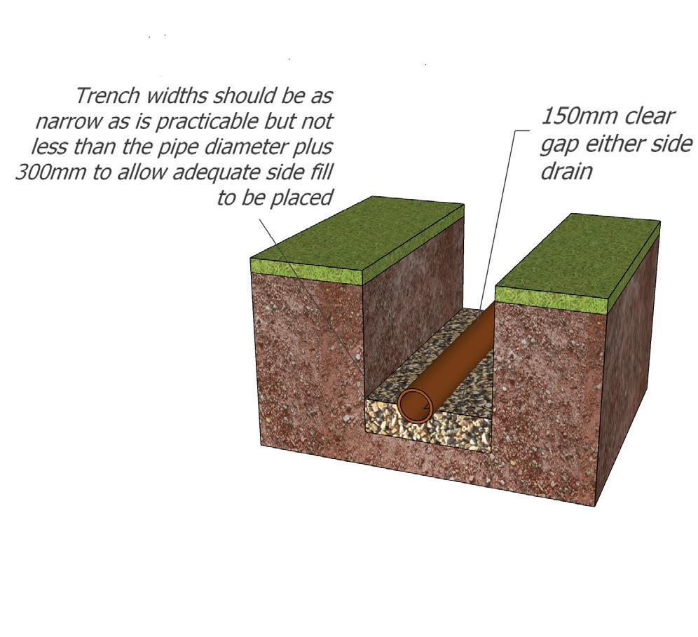
97
7.1
7.2 ACCESS AND CONNECTION
Inspection Chambers and Rodding Facilities
Access is required to drainage installations for testing, inspection and removal of debris. At all times there should be access and this is achieved by ensuring that each change of direction a suitable inspection chamber is installed and at each pipe end a suitable facility to rod pipes should be installed.
As rodding eyes provide access for clearance of debris in the direction of flow only and they should always be used in conjunction with an access chamber or manhole at a point downstream. No part of the drain or sewer should be more than 50m away from a manhole.
The distance between points should therefore not exceed 100m, guidance should always be made to BS EN 752.
98
7.2
Type Depth to invert from cover level (mm) Internal sizes Cover sizes Length x Width (mm) Circular (mm) Length x Width (mm) Circular (mm) Rodding eye 0mm As drain with min. 100 Same as pipework Small access fitting 150 dia 150 x 150 0.6 or less, except where situated in a chamber 150 x 100 150 150 x 100 Same size as access fitting Large access fitting 225 x 100 225 x 100 225 225 x 100 Same size as access fitting Shall inspection chamber 0.6 or less 225 x 100 190 190 1.2 or less 450 x 450 450 Min. 430 x 430 430 Deep inspection chamber Greater than 1.2 450 x 450 450 Max. 300 x 100 Access restricted to max. 350 Drains up to 150mm Opening can be reduced by 20mm to support cover Larger opening cover can be used with restricted access for health and safety
99 Type Size of Largest Pipe (DN) (mm) Min Internal Dimensions Min Clear Opening Size Rectangular length x width (mm) Circular diameter (mm) Rectangular length x width (mm) Circular Diameter (mm) Manhole up to 1.5m deep to soffit 150 or less 750 x 675 1000 750 x 675 N/A 225 1200 x 675 1200 1200 x 675 300 1200 x 750 1200 Greater than 300 1800 x DN+450 DN+450 or 1800 (whichever is the largest) Manhole greater than 1.5m to soffit 225 or less 1200 x 1000 1200 600 x 600 600 300 1200 x 1075 1200 375 - 450 1350 x 1225 1200 Greater than 450 1800 x DN+775 DN+775 or 1800 (whichever is the largest) Manhole shaft greater than 3m deep to soffit pipe Steps 1050 x 800 1050 600 x 600 600 Winch 900 x 800 900 600 x 600 600 Ladder 1200 x 800 1200 7.2
7.3 CONNECTIONS 7.3
Where half round channels are used in inspection chambers and manholes the branches up to and including 1500mm diameter should discharges into the channel in the direction of flow at or above the level of the horizontal diameter. A branch with a diameter >150mm should be set with the soffit level with that of the main drain. Where the angle of the branch is more than 45 degrees a three-quarter section branch should be used. Channels and branches should be benched up at least to the top of the outgoing pipe and at a slope of 1 in 12. The benching should be rounded at the channel with a radius of at least 25mm.
7.4 GULLIES
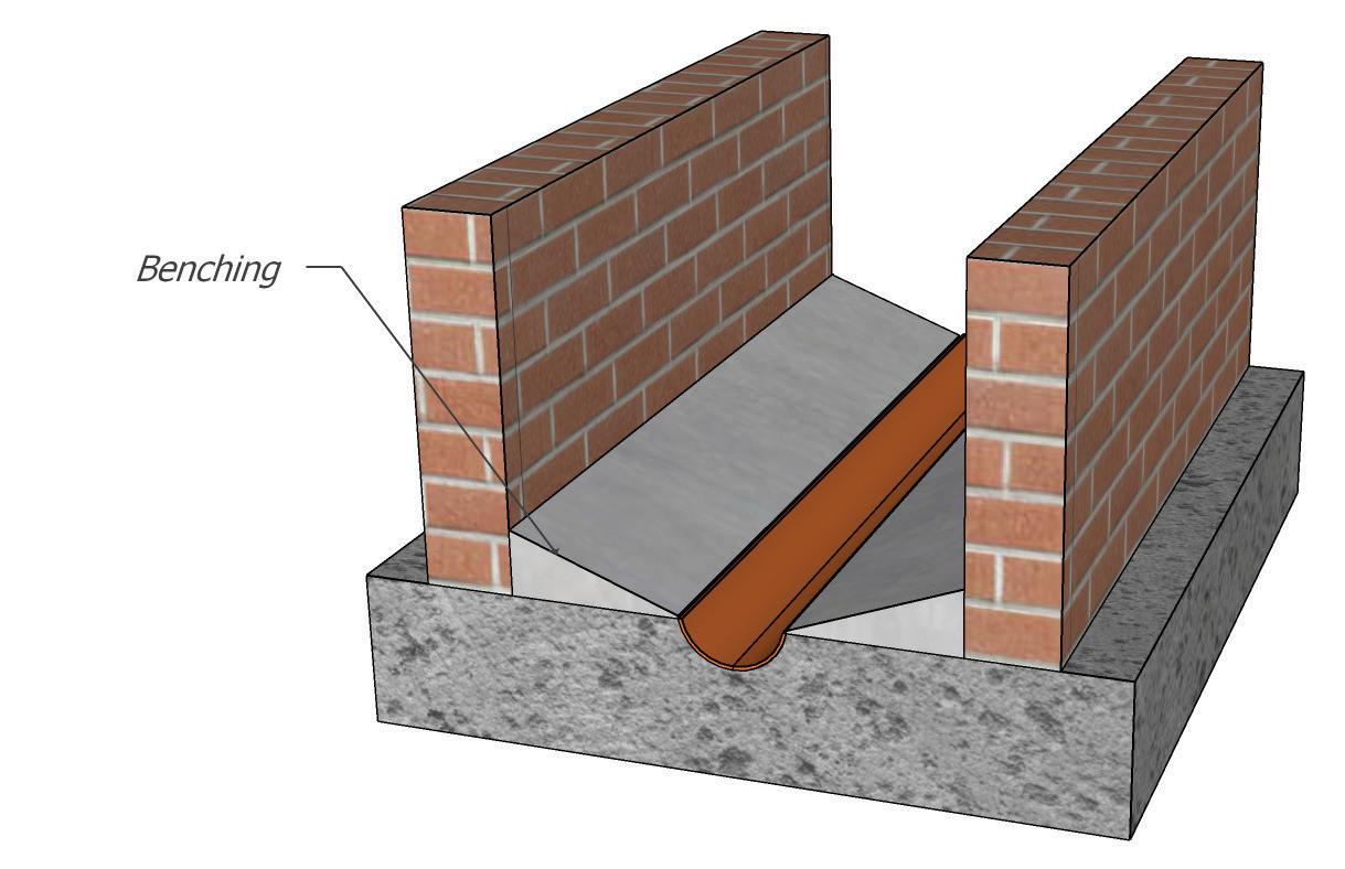
Gullies should always be provided where drives, paths and hard standings with impervious surfaces drain into a rainwater system. Gullies should be levelled with the correct bedding material. Hard materials should not be used as temporary support to achieve gradients as the can create hard spots which can distort the finished pipe runs.
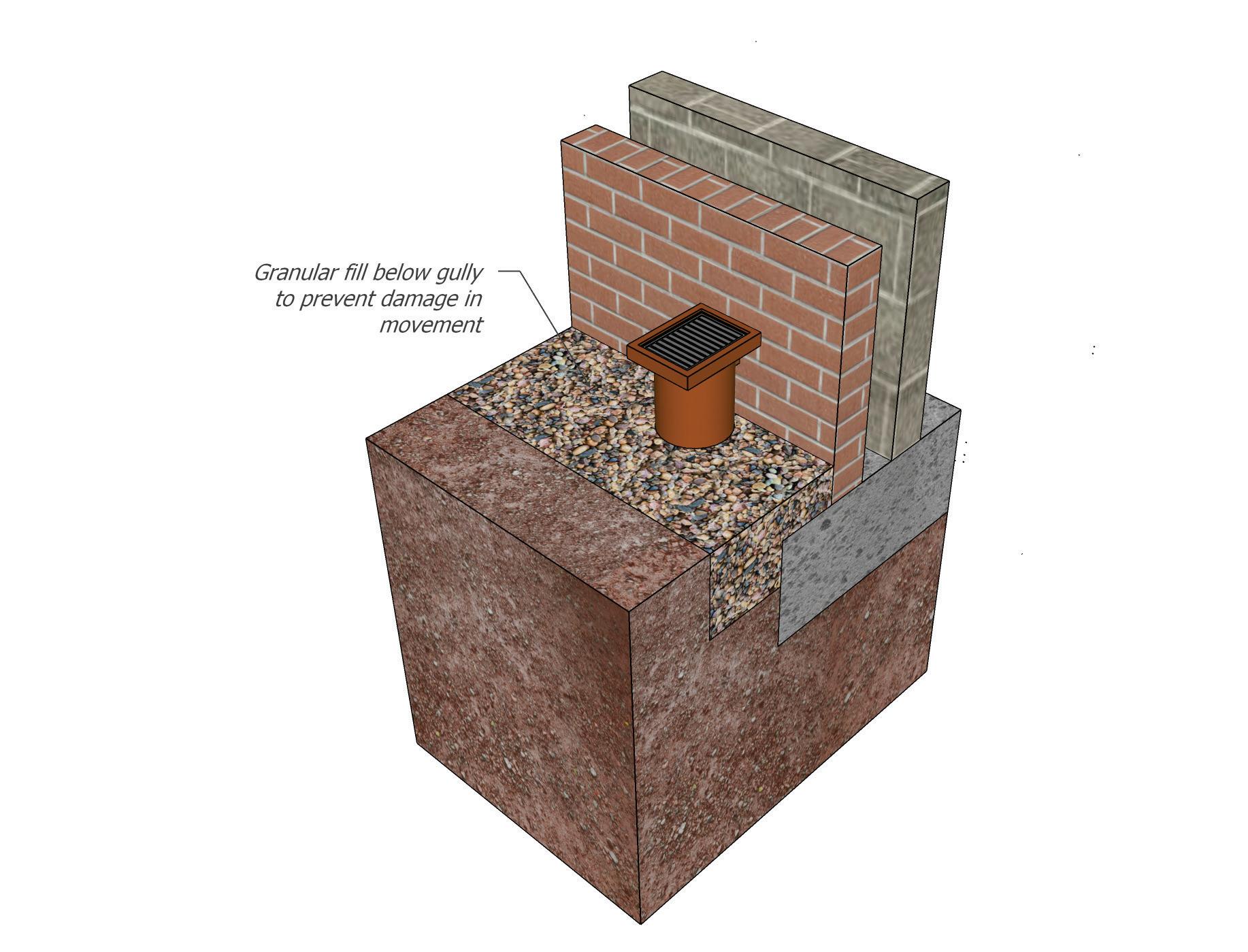
100

7.5 BEDDING MATERIAL
Granular material for bed & surround of uPVC drains and sewers should comply with the requirements of BS EN 13242.
Pipe size
Flexible 110mm/ Rigid 100mm
Flexible 160mm/ Rigid 150mm
Bedding in accordance with BS EN 13242
Bedding gravel 4/10mm
Bedding gravel 2/14mm
7.6 BACKFILL MATERIAL
It is acceptable that material excavated as part of the initial excavation will be deemed suitable if it is free from the following:
• Boulders
• Building rubble
• Timber
• Plastic
• Vegetable matter
• Contaminants
It is advisable that backfill material should be compacted in 300mm layers, care should be taken when using compaction equipment.
Pipes for drainage should comply with the following
British Standards:
• BS 4962 – Plastic pipes
• BS 1194 – Concrete porous pipes
• BS 65 or BS 1196 – Clayware pipes
101
7.5
7.7 FLEXIBLE PIPES
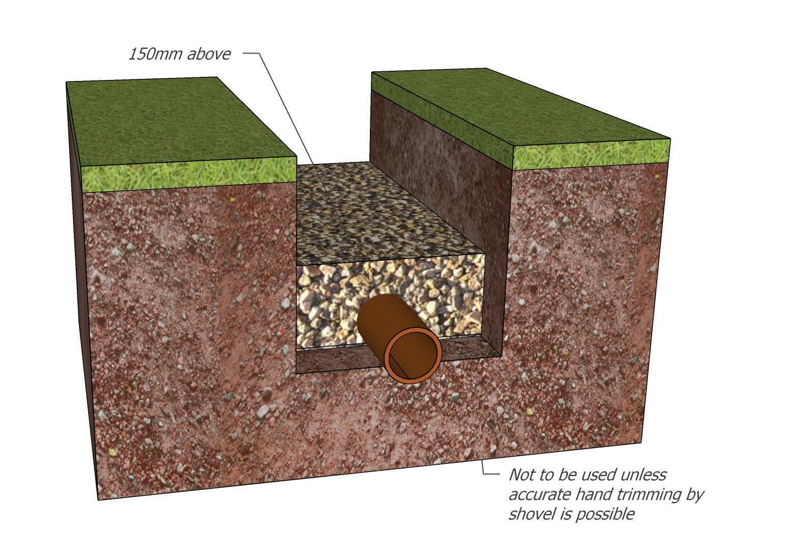
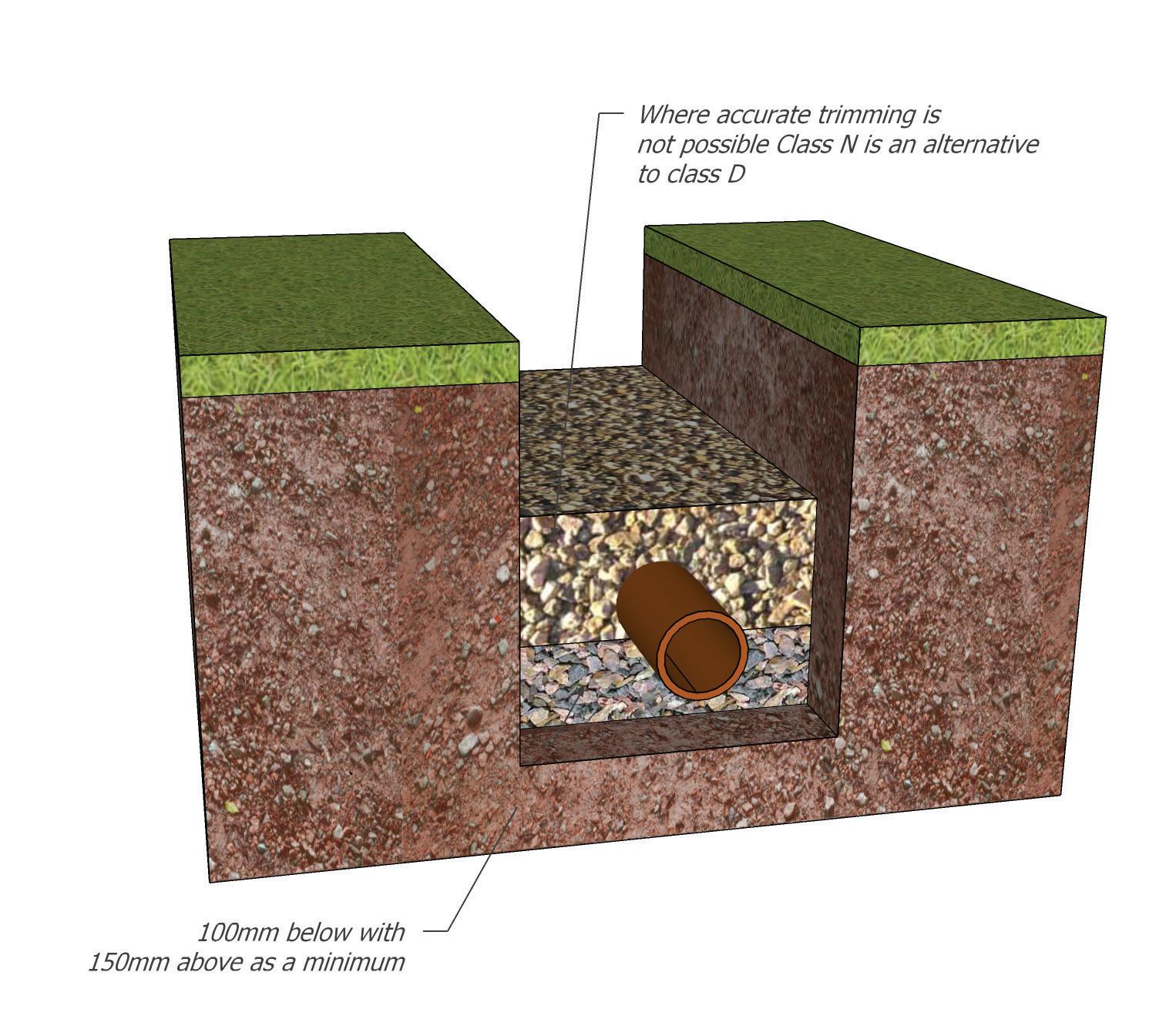
102
7.7 Class D: Bedding Factor 1.1 Class N: Bedding Factor 1.1
Where accurate hand trimming is not possible Class N is an alternative to class D.
7.8 DRAINAGE SYSTEMS
Combined Systems of Drainage
In some instances, especially on older properties there may be instances where the surface water and foul water systems are combined.
Paragraph 3.5 of Approved Document H3 states that: Some sewers carry both foul water and surface water (combined systems) in the same pipe. Where they do the sewerage undertaker can allow surface water to discharge into the system if the sewer has enough capacity to take the added flow (see Approved Document H1 paragraph 2.1).
Some private sewers (drains serving more than one building that have not been adopted by the sewerage undertaker) also carry both foul water and surface water. If a sewer operated as a combined system does not have enough capacity, the surface water should be run in a separate system with its own outfall.
Soakaways
The Building Regulations Approved Document H places the list of priority for the discharge of surface water firstly by means of a soakaway. The process of soakaway design should be designed by a competent person and guidance used in BRE 365 Soakaway design should be adopted.
The ground conditions have a significant impact on whether the water can permeate into the strata and in some instances, this may not be the case.
In general, as site that is deemed to be suitable would have the following:
• Be lower than the area being drained, i.e. have sufficient falls.
• Be located at least 5m away from the habitable part of the building: Approved Document H.
• Located away from the foundations.
• A design that complies with BRE 365.
• Be situated so that there is no risk of contamination from pollutants.
• Minimum gradients for drainage to be 1:80 for 100mm diameter pipes; 1:150 for 150mm diameter pipes; or to manufacturers’ recommendations.
Foul Water Drainage System
Any foul water taken from a sink, bath, shower, toilet, washing machine or dishwasher is deemed to be foul water and should be disposed of in accordance of the requirements of Approved Document H of the Building Regulations. Foul water must be treated where surface water does not so the requirements differ in that the local water authority will treat this water at a designated treatment works.
Septic Tank Systems, Treatment Plants, Cesspits
It is common especially in rural locations that mains sewerage is not present, and the use of a water treatment or cesspool is required. There are a variety of systems that can be used and installed to differing levels of capacity and outfall requirements. It is advisable that as a minimum the guidance found in Approved Document H (H2) is followed. In some instances, you may need environment agency consent to discharge and the necessary approvals should be sought prior to installation.
103
7.8
7.9 ABOVE GROUND DRAINAGE
All roofs will require the provision of gutters and falls pipes which should be installed as per manufacturer’s instructions and flow rates should be calculated to ensure the free flow of water movement. Sizes and dimensions should follow the guidance of Approved Document H and the table below:
Septic Tank Systems, Treatment Plants, Cesspits
It is common especially in rural locations that mains sewerage is not present, and the use of a water treatment or cesspool is required. There are a variety of systems that can be used and installed to differing levels of capacity and outfall requirements. It is advisable that as a minimum the guidance found in Approved Document H (H2) is followed. In some instances, you may need environment agency consent to discharge and the necessary approvals should be sought prior to installation.
Above Ground Drainage
Within the fabric of the building there will be various drainage systems to accommodate the free flow of water to the below ground system. All of this drainage must be designed and installed to the manufacturer’s standards and specifications. All above ground plumbing systems need to be designed to allow the unobstructed flow of wastewater from an appliance to the underground drainage system.
104
7.9
Max Effective Roof Area (m2) Gutter Size (mm dia) RWP Outlet Size (mm dia) Flow capacity (ltr/sec) 18 75 50 0.38 37 100 63 0.78 53 115 63 1.11 65 125 75 1.37 103 150 89 2.16
7.10 DRAINAGE LAYOUT
The layout of the drainage system should be kept simple. Changes of direction and gradient should be minimised and as easy as practicable. Access points should be provided only if blockages could not be cleared without them. The below bullet points refer to paragraphs taken from Approved Document H and should always be followed.
• Connection of drains to other drains or private or public sewers, and of private sewers to public sewers should be made obliquely, or in the direction of flow.
• Connections should be made using prefabricated components. Where holes are cut in pipes a drilling device should be used to avoid damaging the pipe.
• Where connections made to existing drains or sewers involve removal of pipes and insertion of a junction, repair couplings should be used to ensure a watertight joint and the junction should be carefully packed to avoid differential settlement with adjacent pipes.
• Sewers (serving more than one property) should be kept as far as is practicable away from the
point on a building where a future extension is likely (e.g. rear of a house, or side of house where there is room for a side extension).
• The system should be ventilated by a flow of air. A ventilating pipe should be provided at or near the head of each main drain. An open ventilating pipe (without an air admittance valve) should be provided on any drain fitted with an intercepting trap (particularly on a sealed system), and on any drain subject to surcharge. Ventilated discharge stacks may be used. Ventilating pipes should not finish near openings in buildings.
• Pipes should be laid to even gradients and any change of gradient should be combined with an access point
• Pipes should also be laid in straight lines where practicable but may be laid to slight curves if these can still be cleared of blockages. Any bends should be limited to positions in or close to inspection chambers or manholes and to the foot of discharge and ventilating stacks. Bends should have as large a radius as practicable.
105 7.10
Appliance Max no. to be connected Max. length of branch pipe (m) Min. size of pipe (mm) Gradient limits (mm fall per metre) WC outlet >80mm 8 15 100 18 to 90 WC outlet <80mm 1 15 75 18 to 90 Urinal - Bowl 31 50 18 to 90 Urinal - Trough 31 65 18 to 90 Urinal - Trough 31 Washbasin or bidet 3 1.7 30 18 to 22 1.1 30 18 to 44 0.7 30 18 to 87 3 40 18 to 44 4 4 50 18 to 44 Not recommended where disposal of sanitary towels may take place via the WC May be reduced to 9mm on long drain runs, where space is restricted, but only if more than 1 WC is connected Should be as short possible to prevent deposition
7.11 VENTILATION
Within or external to the building there will be a need to provide a means of ventilation to the drainage system.
Air Admittance Valves
Where air admittance valves are used to terminate soil pipes, they should comply with the Building Regulations Approved Document H. Valves within the building should be:
• Positioned in areas which are not liable to freezing.
• Positioned in areas which have adequate ventilation.
• Accessible for maintenance.
When air admittance valves are installed within the loft space the valve should be:
• Installed vertically.
• Installed 150mm above the insulation level.
Venting to Atmosphere
• Ventilating pipes open to outside air should finish at least 900mm above any opening into the building within 3m and should be finished with a wire cage or other perforated cover, fixed to the end of the ventilating pipe.
• A ventilating pipe should be provided at or near the head of each main drain. An open ventilating pipe (without an air admittance valve).
If the discharge stack provides the only ventilation to septic tanks or cesspits, the connecting drain is subject to periodic surcharging or is fitted with intercepting traps, air admittance valves are not suitable ventilation.
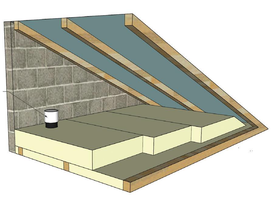
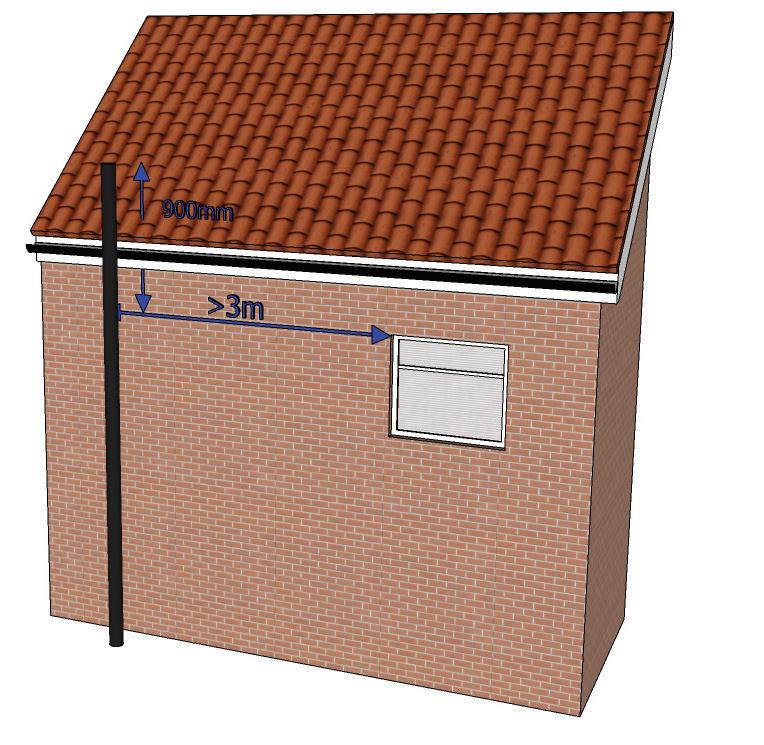
106
7.11
Min 150mm above the insulation
7.12 TESTING
Flow must be maintained from all plumbing systems and guidance found in Approved Document H of the Building Regulations should be implemented as a minimum standard.
The unobstructed flow of waste in all above ground plumbing systems will be allowed from an appliance to the underground drainage. This will be achieved by following the notes below at design and installation stages:
• Pipe and gutter sizes are adequate to take the expected rate of discharge and are laid at suitable gradients with the minimum of direction changes.
• 75mm deep seal traps should always be used except on a WC or where an appliance on the above ground drainage system.
• Pipe sizes should not exceed the dimensions for diameter against pipe length;
• Pipe sizes should be laid at a gradient of 1/80 or better.
• Venting to the external wall at the highest point of a drainage system (head of run).
• At the head of underground drains ventilation is
to be provided. Either by a soil pipe, or a separate ventilation pipe.
• A soil or ventilation pipe should extend at least 900mm above an opening if it is less than 3m away from an opening into the building.
Testing of Drainage
• Fill drainage pipes and leave for a one-hour period then release the bungs to inspect flow.
• The test pressure should then be maintained for a period of 30 minutes, by topping up the water level as necessary so that it is within 100mm of the required level throughout the test. The losses per square metre of surface area should not exceed 0.15 litres for test lengths with only pipelines or 0.20 litres for test lengths including pipelines and manholes, or 0.40 litres for tests with only manholes and inspection chambers alone.
107
7.12
Flow Rates from Dwellings No of dwellings Flow rate (ltr/sec) 1 2.5 5 3.5 10 4.1 15 4.6 20 5.1 25 5.4 30 5.8 Flow rates
108
GROUND FLOOR
109
8.0
8.0 GROUND FLOORS
Statutory Requirements
Roles and Responsibilities
When considering ground floor design this should be linked directly to the site investigation report. It is the responsibility of the developer to ensure the correct ground floor is provided and inspected.
Building Regulations
The requirements of Approved Documents of the Building Regulations 2013 should be followed, and relevant approvals sought from the Building Control Body.
Any ground bearing floor construction which requires structural engineer’s details should be sought prior to the installation of the floor. The design should ensure that the structural integrity meets the requirements needed to safely distribute loads to the foundations and the ground.
Any contamination, including gases, sulphates etc. should be identified at the site investigation stage and appropriate measures taken to address these issues.
Workmanship
During the construction phase:
• All workmanship must be completed in a competent workmanship like manner.
• Protected against unnecessary damage.
• Design and Installation specifications are followed.
• Products and materials are inspected for suitability for their purpose.
Materials
All materials used shall:
• Be adequately protected and stored in a correct manner.
• Comply with relevant British Standards or equivalent European Technical Specification with the certification available for inspection by ICW.
• Be installed as per Manufacturers details.
• Have a life span of 60 years when used as part of the structure, however it is accepted that materials that are not an integral part of the structure may require maintenance and or replacement within this period.
Design
Where a specialist design is requested or required, they shall:
• Be designed by a suitably qualified person.
• Be supplied with clear precise instructions.
• Be supported with structural calculation when outside the guidance of the Approved Documents.
• Be available for inspection by ICW
110
8.0
8.1 GROUND BEARING FLOOR SLABS
All topsoil including organic material, tree roots and vegetation shall be removed prior to construction of the slab. The hardcore should be certified fit for purpose and compacted no greater than 5 times its nominal value. Appropriate compaction equipment should be used.
There should be an adequate Damp Proof Membrane installed and guidance found in Approved Document
C: Diagram 4 and Technical solution in paragraph 4.7 followed.
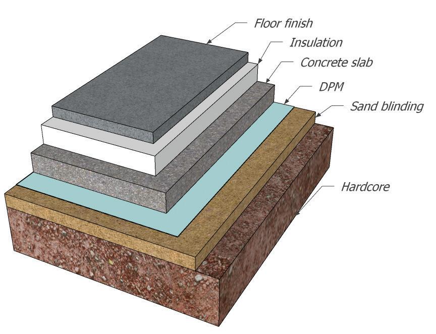
Where reinforcement is required suitable structural details should be provided as part of the floor design by a suitably qualified person.
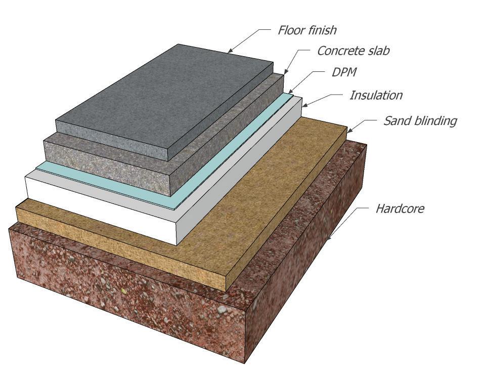
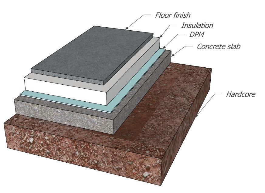
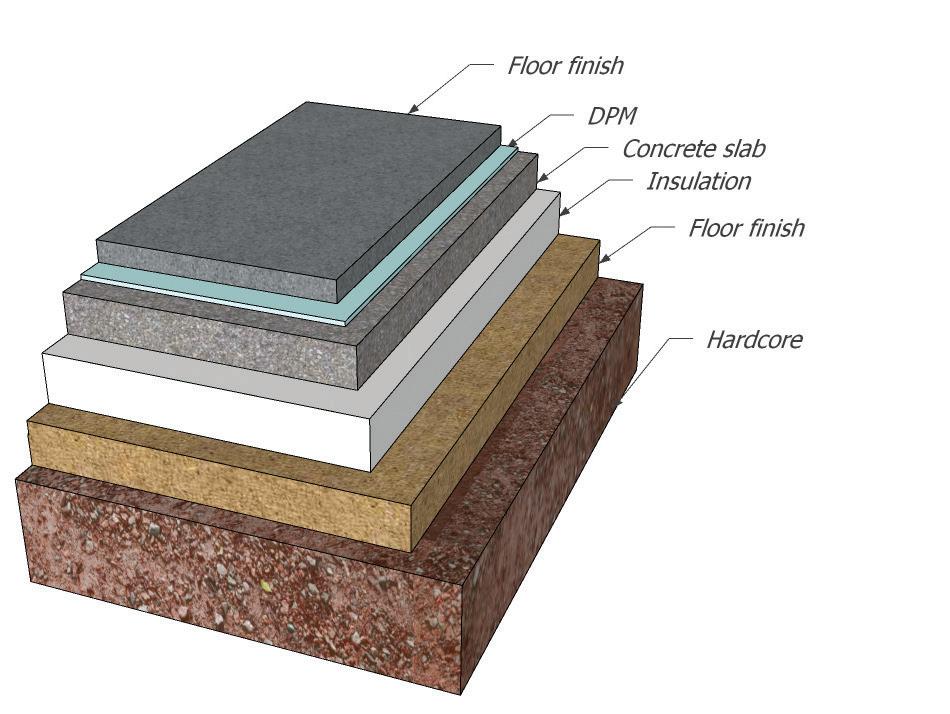
111
Damp-Proof Membrane Above Slab
Damp-Proof Membrane Above Slab
Damp-Proof Membrane Above Slab
8.1
Insulation Below Slab
8.2 PRECAST BEAM AND BLOCK FLOORS
Precast Beam & Block Floors
Any details of precast floors including beam and block should always be provided prior to installation and the manufacturer’s installation technique followed. Any walls supporting the precast beam and block floor should be suitably designed by a competent person and designed to adequately support the loads.
Guidance can be found in Approved Document C, Technical Solution Paragraph 4.18. Cross ventilation should also be provided to the void beneath the beam and block floor, and a minimum void depth of 150mm should be provided below the underside of the floor structure to the top of the ground level.
When installing block and beam suspended floors ensure:
• Joist are located above DPC level.
• Min 150mm gap is provided between underside of joist and oversite. When shrinkable clays are present min gap of 225mm to be provided between underside of beam and oversite.
• Beams are bearing on to the inner leaf of the cavity wall and do not project into the cavity.
• Installed as per manufacturers details.
• Provision of ventilation to avoid below floor beams:
- Min 75mm above ground level.
- Ventilation to be within 450mm of building corners.
- 2m centres.
- Provision of ventilation through intermediate foundation walls equivalent to external walls.
- Position of ventilation to consider heave in shrinkable clay to prevent blockage.
- Position of vents must be situated on opposite elevations.
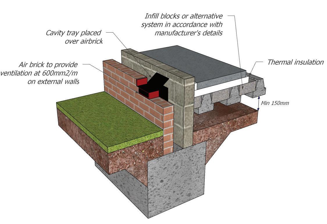
112
8.2
8.3 SUSPENDED TIMBER FLOORS
Any walls supporting the timber floor should be suitably designed by a competent person and designed to adequately support the loads. A suitable concrete oversite should be provided beneath all suspended timber floors. It is recommended that guidance found in Approved Document C: Technical Solution 4.14 is followed.
Cross ventilation should be provided to the void beneath the timber floor, and there should always be a minimum void depth of 150mm below the underside of the floor structure to the top of the ground level.
Depending on the proposed floor finish, the chipboard, OSB or tongued and grooved floorboards are all suitable materials, subject to loading requirements. And all the flooring types should be adequately fixed, preferably by screws.
When installing timber suspended floors ensure:
• Joist are located above DPC level.
• Min 150mm gap is provided between underside of joist and oversite. When shrinkable clays are present min gap of 225mm to be provided between underside of beam and oversite.
• Air bricks are a min of 75mm above ground level.
• Joists are bearing on to the inner leaf of the cavity wall and do not project into the cavity.
• Joists are correctly sized.
• Joist are adequately strutted.
• Provision of ventilation to the void below floor beams:
- Min 75mm above ground level.
- Ventilation to be within 450mm of building corners.
- 2m centres.
- Provision of ventilation through intermediate foundation walls equivalent to external walls.
- Position of ventilation to consider heave in shrinkable clay to prevent blockage.
- Position of vents must be situated on opposite elevations.
- fire risks considered
- timber floor designer to confirm durability through ventilation provision.
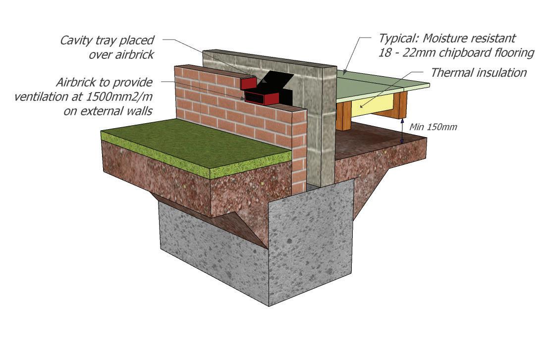
113
8.3
8.4 DAMP ROOF
MEMBRANES
It is recommended that all DPMs should be a minimum of 1200 gauge, and laid on a sand blinding to prevent puncture, as shown in Approved Document C: Diagram 4. DPMs should be provided to all ground bearing concrete slabs, reinforced concrete slabs, precast beam and block floors and to over sites of suspended timber floor structures.
It is recommended that all DPMs are continuous, however, often due to service installation this is not always possible, so it is recommended that where joints are created the joint is suitably sealed with appropriate tape. An additional layer may be required subject to the inspection of the inspector.
DPM taped overlaps of at least 300mm
A dew point calculation to be provided to ensure adequate insulation / ventilation provision
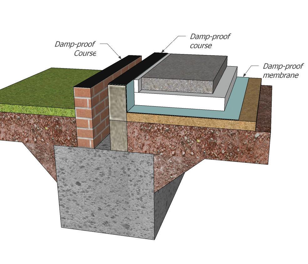
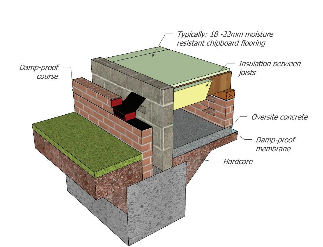
/ adequately fixed to prevent ‘sagging’
114
DPC
8.4
8.5 RADON GAS BARRIER
Radon is a colourless, odourless radioactive gas which is formed by the decay of uranium that naturally occurs in all rocks and soils. Radon is everywhere, although in many areas the levels are low, so present little danger to public health.
Public Health England have prepared maps indicating the chance of a building having a high radon level. These maps cover England, Wales, Scotland and Northern Ireland. Even in the areas with the highest radon level, not all buildings will be deemed to have high levels. These maps can be viewed at www.ukradon.org.
Radon enters a building via small gaps and cracks that are formed throughout the building’s life. The atmospheric pressure difference between the inside and outside causes the gases to be drawn up through the soil and into the building.
Public Health England recommends that radon levels should be reduced in homes where the average is more than 200 becquerels per metre cubed (200 BQ/m3). This recommendation has been endorsed by the government. This action level refers to the annual average concentration in a home. Radon measurements are carried out with two detectors (in a bedroom and living room) over three months (to average out the short-term fluctuations).
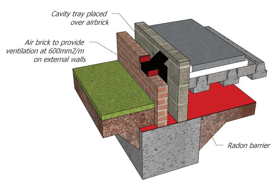
Where radon has been found to exist, it is important to protect from its exposure. In order to do this, a radon barrier must be installed as part of the ground floor construction.
A compliance certificate to be provided for the radon barrier or gas barrier installation.
Radon / gas barriers to be protected prior to further installation of floor screeds etc.
This example avoids creating a horizontal path through the wall. The step must be a minimum of 75mm.
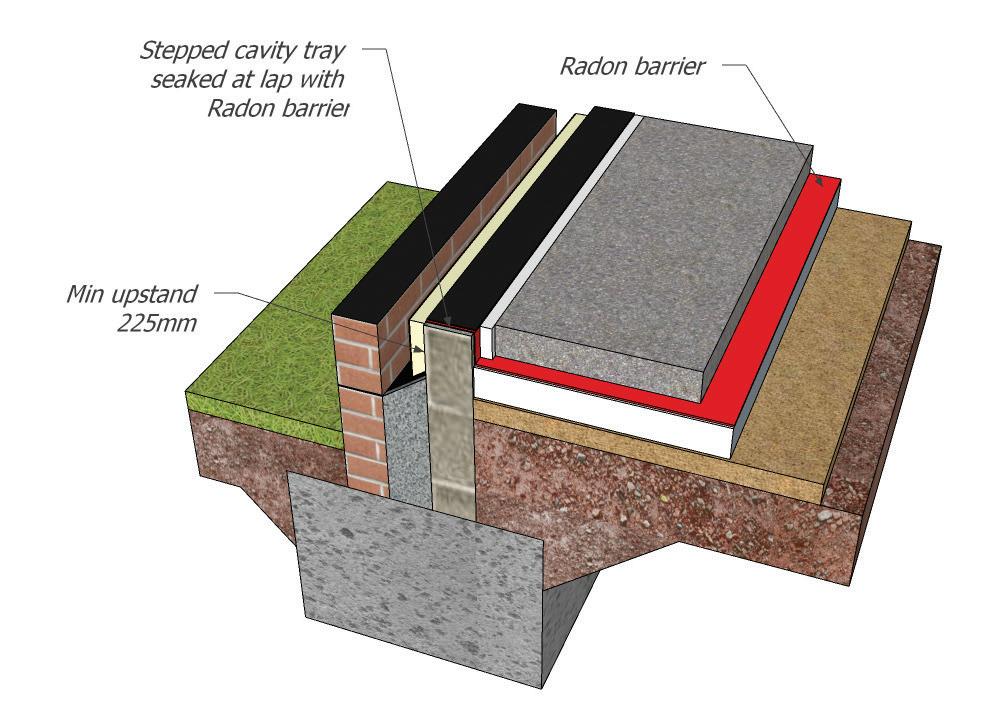
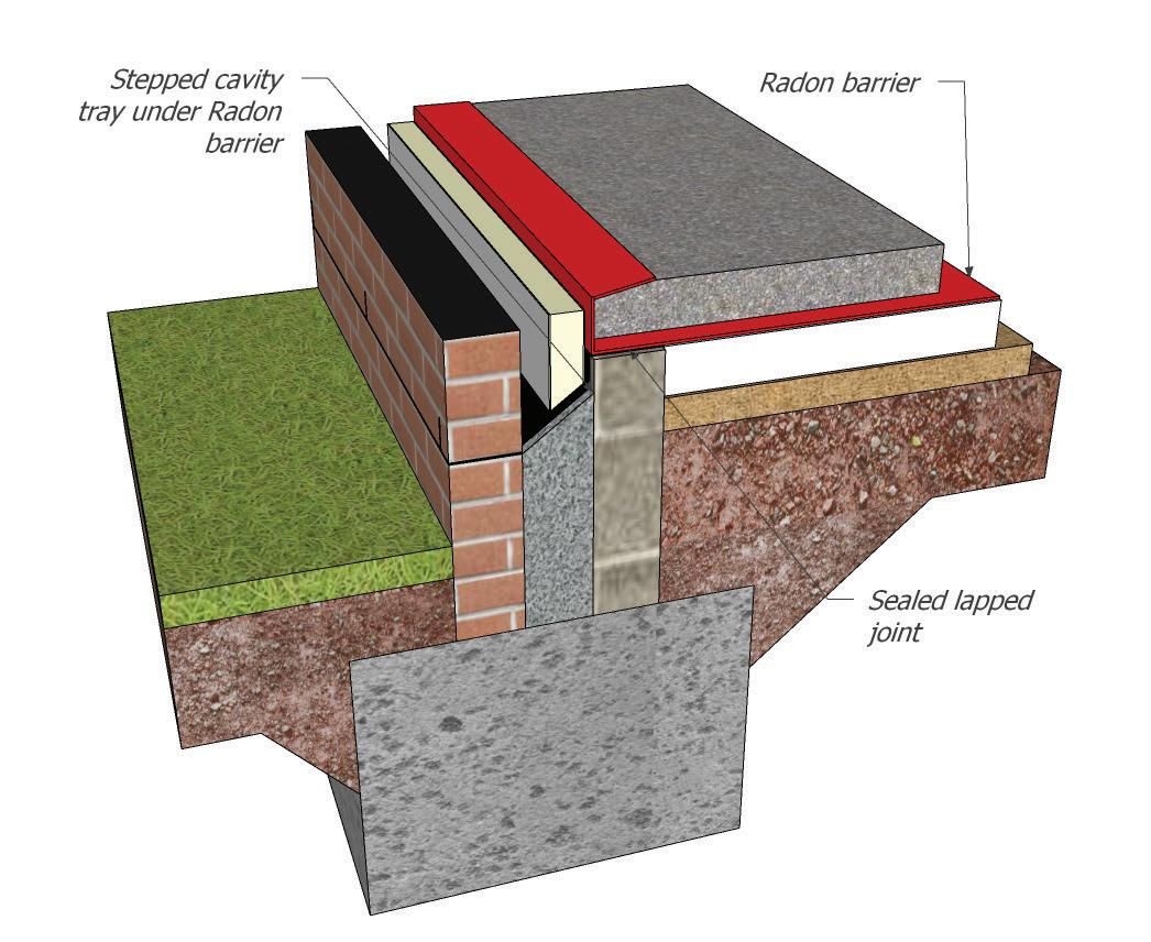
115
8.5
Avoiding jointing materials or stepped trays, it is possible to install the radon barrier as a single horizontal layer. The barrier is laid a minimum of 225mm below external ground level.
116
SUPER STRUCTURE
117
9.0
9.0
9.0 SUPERSTRUCTURE
Statutory Requirements
Roles and Responsibilities
When considering superstructure design this should be linked directly to the site investigation report. It is the responsibility of the developer to ensure the correct superstructure is provided and inspected.
Building Regulations
The requirements of the Approved Documents of the Building Regulations 2013 should be followed, always and all of the relevant approvals sought from the Building Control Body.
If any calculations are required to support the proposed design, then these should be provided by a suitably competent and qualified person. The calculations will need to be designed so as they safely distribute loads and forces to the foundations.
Workmanship
During the construction phase:
• All workmanship must be completed in a competent workmanship like manner.
• Protected against unnecessary damage.
• Design and Installation specifications are followed.
• Products and materials are inspected for suitability for their purpose
Materials
All materials used shall:
• Be adequately protected and stored in a correct manner.
• Comply with relevant British Standards or equivalent European Technical Specification with the certification available for inspection by ICW.
• Be installed as per Manufacturers details.
• Have a life span of 60 years when used as part of the structure, however it is accepted that materials that are not an integral part of the structure may require maintenance and or replacement within this period.
Design
Where a specialist design is requested or required, they shall:
• Be designed by a suitably qualified person.
• Be supplied with clear precise instructions.
• Be supported with structural calculation when outside the guidance of the Approved Documents.
• Be available for inspection by ICW.
118
9.1 EXPOSURE
Countries can be divided into areas rated as sheltered, moderate, severe and very severe exposure to wind driven rain based on extensive metrological studies. There is a link between high exposure areas and the likelihood of brickwork suffering the consequences of frost attack if design, detailing and construction have not been properly addressed.
All areas within 8km of the coast and major river estuaries should be considered as being one ‘grade’ of exposure higher than that indicated on the map. The same applies to high buildings or buildings on high ground. The degrees of exposure will also depend on the position of the brickwork in the building or structure and the way in which the detail has been designed.
Generally external works such as retaining walls, garden walls and copings, and building features such as sloping areas, parapets, sills and areas between ground level and DPC are subject to more severe exposure than the rest of the building. This coupled with the geographical location classed as severe or very severe must be designed and constructed with due consideration.
For areas outside of the UK please refer to the relevant applicable geographic requirements.
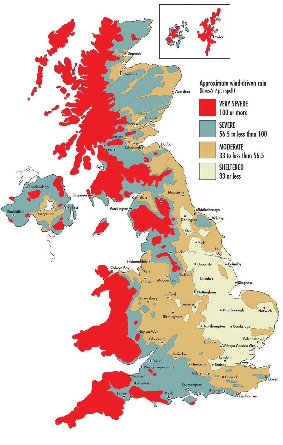
119
9.1
9.2
9.2 BRICKS
BS EN 771 classifies bricks in accordance with their durability designation, In selecting the correct brick it is important to consider the exposure their will face and their location within the structure if in doubt then the standard classification F1,S2 or F1,S1 should be used below and 150mm above the DPC.
One to two storeys
Lowest storey of a three-storey wall or where individual storeys exceed 2.7m
Upper storeys of a three-storey wall
Block 2.9N/mm
Block 9N/mm
Block 7.5N/mm
Block 13N/mm
Block 2.8N/mm
Block 9N/mm
9.3 BLOCKS
Blocks should meet BS EN 771 and have a minimum density of 1500Kg/m2 with a minimum compressive strength of 7.3N/mm2.
120
height Minimum compressive strength of brick or block unit
Wall
9.4 MASONRY PROTECTION
It is advisable that all new masonry should be protected by covering, to ensure that the walls are not saturated by rainwater, or they do not dry out too quickly especially in hot weather. Consideration must also be given in the winter months when we experience reduced temperatures due to frost. Masonry should not be laid in poor weather or temperatures below 2 degrees. Do not use frozen materials.
Insulated boards or heaters may be considered in extreme weather conditions.
Material Suitability
All bricks and blocks must have a suitable level of durability and particular attention should be paid to the brick’s resistance to frost and moisture and comply fully with BS EN 771–1
Non-Rendered Blockwork
All external blockwork should be rendered or otherwise finished with a cladding that is appropriately durable, unless the block manufacturer can provide third party certification confirming that the blockwork can be left unfinished or finished in an alternative way. Approved Document C: Technical Solution 5.9 (b).
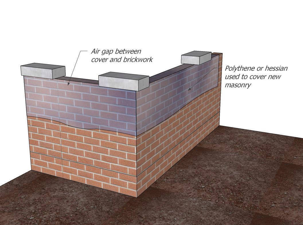
121
9.4
9.5
9.5 MORTARS
Mortar General
All mortars should be fit for purpose and comply with all relevant standards, it is advisable to utilise manufacturer’s guidance. The mixing of the mortar should be continuous to ensure consistency and quality, hand mixing is not recommended, and all mortar should be mixed in a mechanical mixer.
Mortar joints are vulnerable to frost failure and general weathering and may require increased maintenance in regions rated as severe exposure to wind driven rain.
Mortar is an essential ingredient of brickwork and is subject to the same exposure as the brick.
Grade iii
mortar or iv
mortar as per BS 5628-2.
9.6 GENERAL ADVICE ON CAVITY WALLS
A traditional masonry wall should be constructed using an inner and outer leaf and a cavity should be provided:
• In general, the current minimum dimensions for cavities is 100mm subject to SAP.
• The cavity should be kept clear from mortar to ensure there is no bridging.
• Both walls should be tied together using wall ties using guidance in Approved Document A Paragraph 2C8.
• Insulation of the cavity can be full or partial fill depending on exposure to wind driven rain. For partial fill insulation, a minimum clear cavity of 50mm should always be provided as Approved Document C: paragraph 5.15.
122
Location Mix Proportions Aggregate Blocks Airtec Blocks Clay Brick Notes Above DPC Cement: Lime: Sand 1 : 1: 5-6 1 : 2 : 9 or 1 : 1 : 6 1 : 1 : 5
Cement: Sand (with plasticiser) 1 : 5-6 1 : 6 1 : 4 Masonry Cement: Sand 1 : 4-5 1 : 5 1 : 3
9.7 SOLID WALL
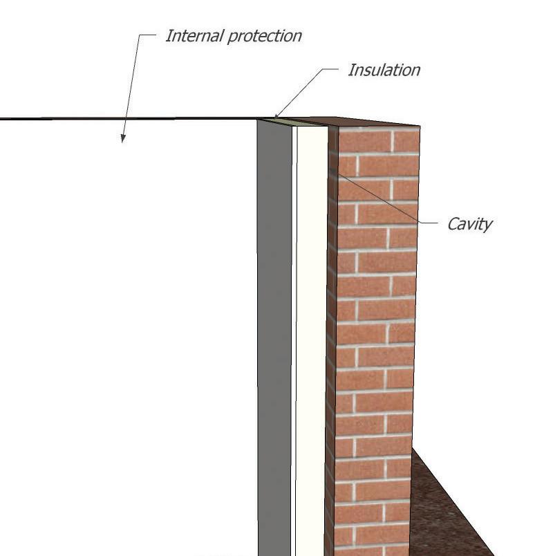
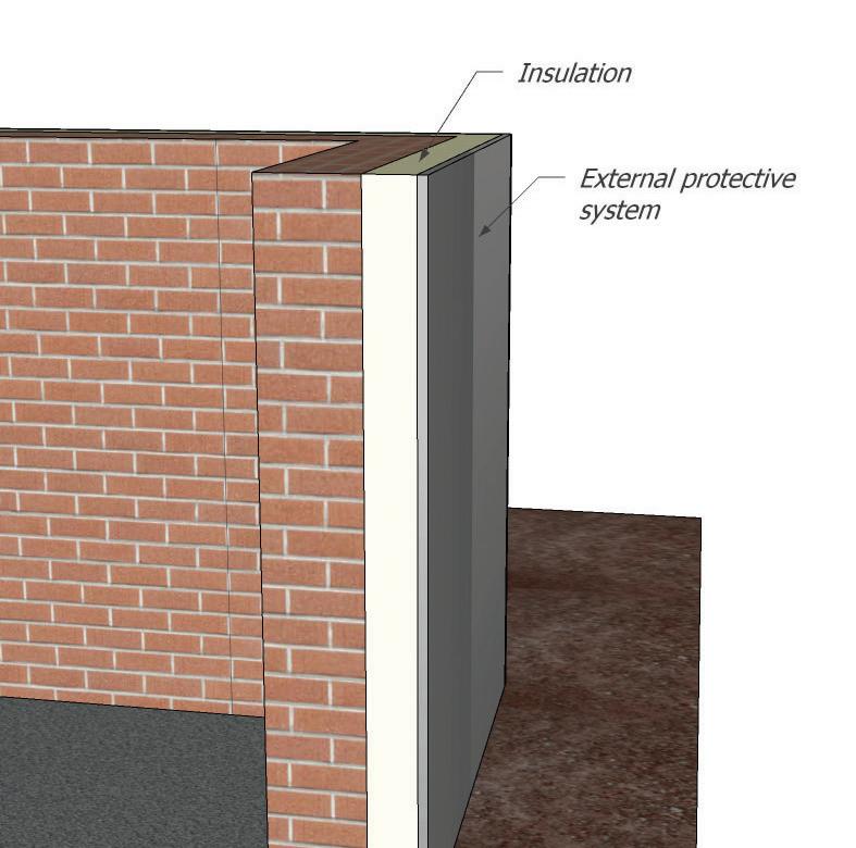
123
9.7 Internal Insulation External Insulation
9.8 CAVITY WALL
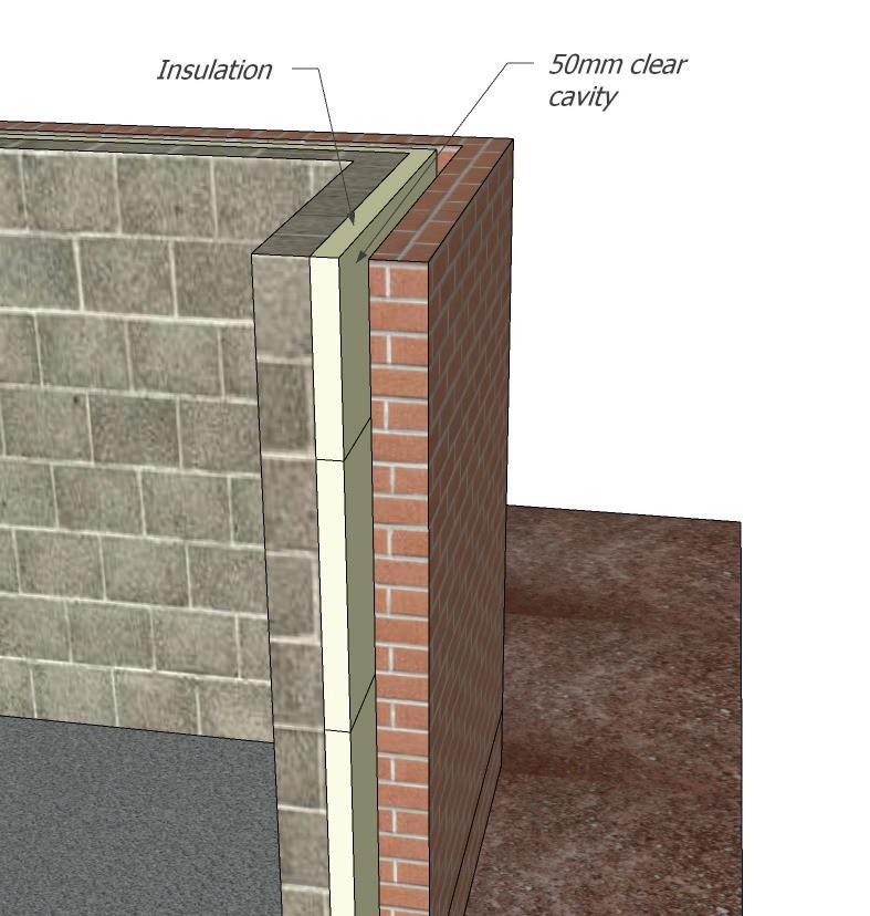
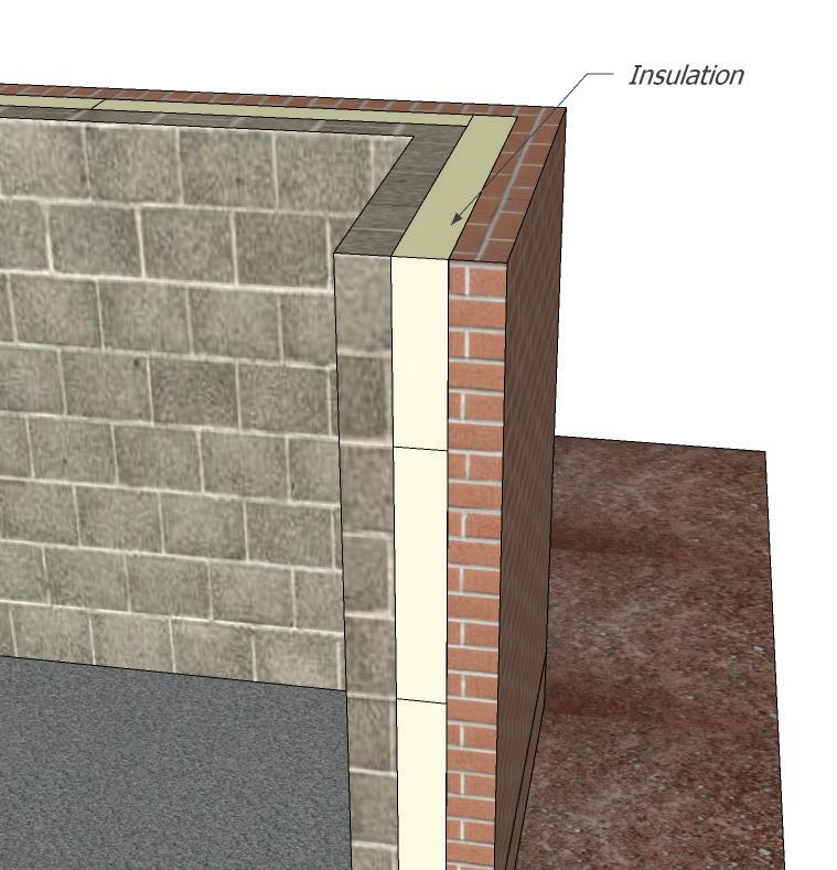
124
9.8 Partial Fill Insulation Full Fill Insulation
9.9 LATERAL RESTRAINT
Wall Restraint
All the walls should be restrained adequately in accordance with the Building Regulations
Approved Document A, and there are a variety of restraint methods can be used. It is advisable to see manufacturer’s details when using restraints and their fixings. Restraint can be provided by:
• Joist hangers.
• Lateral restraint straps.
• Wall Ties.
Joist hangers are suitable for and can be used with connections between wood-based members such as:
• Structural solid timber classified to C14-C40 according to EN 338 / EN 14081.
• Glulam classified to GL24-GL36 according to EN1194 / EN 14080.
• LVL according to EN 14374.
• Intrallam LSL.
• Layered wood plates.
• Engineered timber joints with backer blocks on both sides of the web in the header and web stiffeners in the joist.
When installing joist hangers it is important to ensure that the hanger is bedded directly on the masonry and there is no gap between the hanger back-plate and the face of the masonry, there should be at least 450mm of masonry provided above the hanger and the hanger is spaced subject to the correct centres of timber specification as shown in TRADA table spans.
125
9.9
9.10 LATERAL RESTRAINT STRAPS
Floors should provide lateral restraint to all walls running parallel to them, by means of 30mm x 5mm galvanized or stainless-steel restraint straps at 2m centres. Further guidance can be found in Approved Document A.
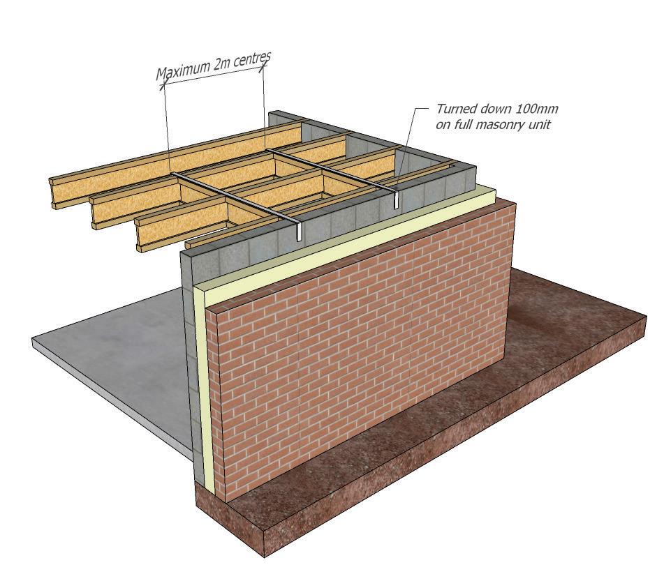
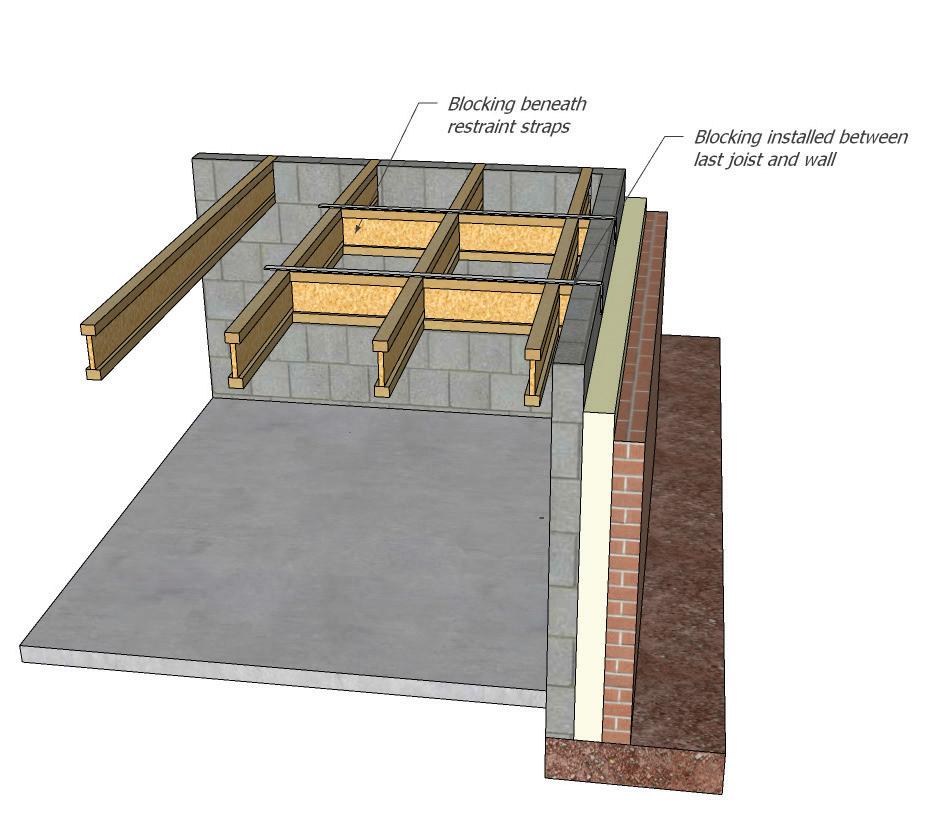
9.11 WALL TIES
Wall ties will be adequate if they meet the following provision:
• They are to BS EN 845-1.
• They should be appropriate for the width of cavity and have at least 50mm bearing on each leaf.
• To be laid to a slight fall towards the outer leaf and have the ability to hold insulation against an internal leaf for partial fill scenarios.
• Stainless steel wall ties should always be used. It is important to note that only BS EN 845-1 type wall ties or specifically manufactured and tested.
• Wall tiles to be reduced to 750mm centres of cavities greater than 100mm.
• Wall tiles used in cavities greater than 150mm to be designed by a structural engineer.
• Wall tiles to be within 225mm of an opening and expansion joints.
126
9.10
9.12 CAVITY CLOSERS
Suitable cavity closers should be installed to all door and window openings and the manufacturers installation guide should always be adhered to.
Guidance followed In Approved Document C: diagram
13 gives visual guidance of cavity closers in cavity walls
Checked rebate.

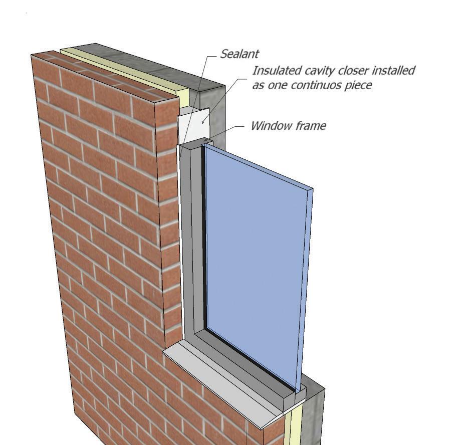
127
9.12
9.13 MOVEMENT JOINTS
Movement in Masonry
Vertical movement joints should be provided to the outer leaf of cavity walls as indicated in Table below. The first joint from a return should be no more than half the dimension indicated in the table.
Movement joints below the DPC should also be provided at major changes in foundation level and at changes in foundation design. Wall ties at a maximum of 300mm centres should be provided each side of movement joints. Compressible filler such as polyurethane foam should be used to form the joint and be sealed to prevent water penetration.
Fibreboard or cork are not acceptable materials for forming movement joints in masonry.
Elastic sealants (Type E) are suitable as they allow for reversible movement.
Movement joint guidance and location should be provided by a Structural Engineer and in accordance with manufacturers information.
Note: It is not normally necessary to provide movement joints to the internal leaf of cavity walls but should be considered where rooms occur with unbroken lengths of wall in excess of 6m.
The first joint from a return should be not more than half the dimension indicated in the table. Movement joints are not acceptable in solid party or separating walls; however, where cavity wall construction is adopted, offset movement joints with a solid rubber compressible strip may be acceptable.
128
9.13
Expansion Joint Spacings Material Normal Spacing Joint Thickness Clay Brickwork 12m (spacing up to 15m may be possible if sufficient restraint is provided – consult Designer) 15mm Calcium Silicate and Concrete Brickwork 7.5 – 9m 10mm Concrete Blockwork (used in outer leaf) 6m 10mm Stone 12m 15mm
9.14 STRUCTURAL OPENINGS
Beams and Lintels
Beams and lintels must be fit for purpose and designed for the loads they will be subject to. They should be installed as per manufacturers details and have suitable end bearing. For guidance generally lintels up to 1.2 meters will require an end bearing of 100mm and lintels over 1.2 meters will require an end bearing of 150mm minimum.
There are a variety of lintels which are acceptable and will take the form of concrete, steel or timber. However, the lintel must be fit for purpose and meet the structural requirements of its intended purpose.
Lintels
When installing lintels, it is recommended that the installation guidance of the manufacturer is always followed and that all lintels are deemed fit for purpose and are correctly insulated, having sufficient moisture resistance, structural integrity and meet the requirements of the relevant Approved Documents.
Masonry should not overhang lintels more than 25mm.
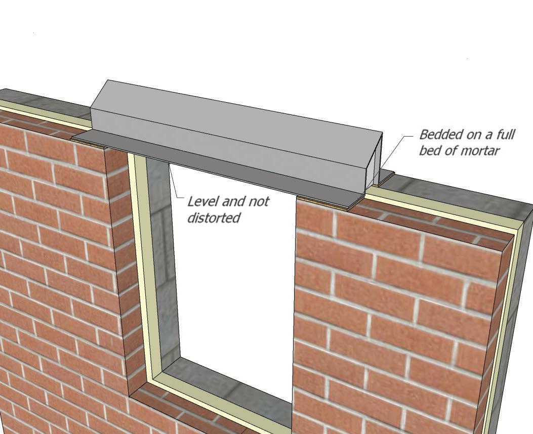
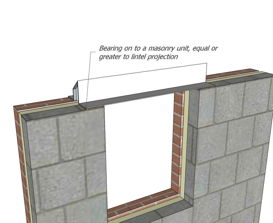
129
Minimum Lintel Bearings (mm)
(mm)
<1.2 100 mm >1.2 150 mm 9.14
Opening Dimension
Lintel Bearing
9.15 CAVITY TRAYS AND DPCS
Cavity Trays
The purpose of cavity trays, weep-holes and stop ends is to prevent the build-up of water within a cavity wall and allow the water to escape through the outer leaf. This can be caused by precipitation or condensation building up within the cavity. Additional guidance and pacing of cavity trays can be found in Approved Document C: Technical solution 5.9 (d). It is advisable that cavity trays are installed in the following situations:
• Above cavity insulation which is not taken to the top of the wall, unless that area of wall is protected by impervious cladding.
• Above rectangular ducts, lintels and recessed meter boxes .
• Above lintels in walls in exposure zones 4 and 3 and in zones 2 and 1.
• Continuously above lintels where openings are separated by short piers.
• Above openings where the lintel supports a brick soldier course.
• Cavity trays to be continuous and not jointed
Weep-Holes
Weep-holes must be installed at no more than 450mm centres and generally have the following characteristics.
• A full height plastics wall weep which corresponds to the height of a standard brick. Incorporates an integral insect guard and wind baffle.
• Provides the maximum clear opening in the mortar joint with no restrictions.
Stop-Ends
When installing cavity trays there should always be a watertight stop-ends to prevent moisture entering the cavity. These stop ends must be bonded to the cavity tray. Normally the stop-end is located to coincide with the nearest perpend to the end of the cavity tray. Stop-ends can be formed by sufficiently turning up the end of a DPC tray into the perpend joint. There should be no mortar build up within the cavity or near to the stop ends.
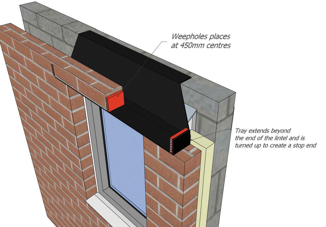
130
9.15
9.16 FLOOR JOISTS
Timber Floor Joists
All floor joists should be correctly sized and graded as per the guidance found in TRADA Span Tables (Eurocode 5).
It is recommended that joists are placed on joist hangers to prevent and distortion through forces such as torsion. The joist should never be overloaded whilst construction is in process and guidance found in TRADA Span Tables (Eurocode 5) provides suitable loading figures per m2
Any joist that is adjacent to an opening such as a staircase should be doubled up and fixed adequately as per structural engineers’ detail, this may take the form of bolting together.
Pre-Cast Beam and Block Floors
Pre-cast beam and block floors are an alternative to timber. If using this form the installation method must be as manufacturer’s details and the masonry supporting the beam will be calculated accordingly to ensure the forces and loads applied are transferred through the structure into the foundations. The blocks should be grouted together with a 1:6 cement / sand mix in accordance with the manufacturer’s instructions.
131
9.16
9.17 ENGINEERED WOOD AND I JOISTS
Engineered Wood, ‘I’ joists and open metal web trimmed joists ‘Posi-joists’ are acceptable flooring joists and must meet the structural requirements calculated by competent person and/or the manufacturer. These types of products can be installed using joist hangers or built into masonry walls ensuring 90mm bearing is achieved (the joist ends must not extend into the cavity void).
Lateral restraints are required to joists that are positioned parallel to the structure and a top chord restraint/ perimeter noggins are also required between joist ends.
Proprietary products with third party accreditation, designed and installed to manufacturer’s recommendations are acceptable to ICW.
Engineered Wood and I joists comprise a timber flange (typically solid timber or LVL – laminate veneer lumber) and a panel product web (usually OSB oriented strand board, fibre hardboard or metal open webbing). They are manufactured in a variety of depths and flange widths under carefully controlled factory conditions to low and uniform moisture contents.
These products can also be assembled off-site to form modular flooring systems producing floor panels and cassettes. They are pre-floored or ‘decked’ in a factory ready for delivery and mechanical placement on site.
Joists should be protected from the elements on suitable bearers over a free-draining surface. Levels of exposure that are more severe than those encountered during normal continuous build programme should be avoided or addressed by the provision of suitable protection.
Large areas of floor joists can be assembled using these products due to their lightweight and availability in relatively long lengths. It is extremely important, though, that adequate safety bracing is provided to ensure that the joists remain stable during the construction phase. Joist manufacturers provide simple guide recommendations to allow the installer to facilitate this process quickly and easily.
Do not allow workers to walk on unbraced joist layouts. Ensure, as with all flooring systems, that the floors do not become overloaded during construction.
The design of these members should be undertaken using design values obtained from the relevant third-party product certifications, generally available from manufacturer’s websites. These products are proprietary and cannot be substituted without design verification.
Service penetrations to be agreed with the designer. Notching and drilling of these products is restricted and should be undertaken in accordance with the reference charts and tables that should be provided to you by the joist manufacturers. Under no circumstances should the flanges of these engineered products be cut, notched or drilled. Components are assembled using standard details, connectors and fixings. The details below illustrate the different approach for these types of engineered joists. Permanent rows of intermediate blocking are not required.
Where any doubt exists relating to the design, specification or installation of these products then contact should be made with the technical department of the respective manufacturer.
132
9.17
The following details are representations of the type of detailing for floor construction when used within masonry walled buildings.
The building designer is responsible for ensuring that details are appropriate for the end application.
133 90mm min mum bearing Jo sts or must not extend nto cavity M nimum 45mm bear ng for internal walls Full depth block ng or Minimum 38mm x 38mm perimeter noggin for floor deck support Similar noggin may be required for ceil ng edge support Noggin to be set 15mm to 25mm from wal Nogg n skew nailed or fixed us ng Z clip For single skin external wa l construction use masonry hangers Finnseal f tted us ng 1no 3 35mm nail per flange Fu l depth block ng or m nimum 38mm x 38mm per meter noggin for floor deck support Similar nogg n may be requ red for cei ing edge support Noggin to be set 15mm to 25mm from wall Nogg n skew nailed or fixed us ng Z c ip Mortar infi l For single skin external wall construction use masonry hangers Plastic Sleeve to be f tted in accordance with manufacturer s instructions Fu l depth blocking or m nimum 38mm x 38mm per meter nogg n for floor deck support Simi ar nogg n may be requ red for cei ing edge support Noggin to be set 15mm to 25mm from wa l Noggin skew na led or fixed us ng Z clip Restra nt strap where required Plastic st ffeners to be nserted where required n accordance with sleeve manufacturer s instructions Web st ffeners must be f tted to the ends of I-Jo sts The ends of al oists and beams should be sealed w th silicon mastic Instal ation Note: Ensure bearings are flat eve and that the joists are vertical For sing e skin external wall construction use masonry hangers
M1c
M5a&b M1b M2a&b M1c
M1b Timber blocking equal to half the jo st depth So id blocking between I-Jo st and wall 25mm space between wal and joist flange CROSS SECTION 5 x 30mm galvanised restraint straps to wall designer s spacing Do not cut flange Strap located n slot in web Care is needed to form slot Strap continuous through 38mm x 8mm deep slot in webs M2a 90mm m nimum bearing F nnsea must not extend into cavity M nimum 45mm bear ng for nterna walls
WALL (Plastic sleeve)
WALL (Joists built in)
WALL (Finnseal) RESTRAINT STRAP (I-Joist parallel to wall)
M7a&b
M3/M4
M1a
CAVITY
CAVITY
CAVITY
Please ensure all solid timber used is dried to the suitable Service Class level. Insta lation Note: Ensure bearings are f at level and that the joists are vertical Installat on Note: Ensure bear ngs are flat level and that the oists are vert cal 9.17
M2b
M3
134 M5a M5b M6 M7a M7b Per meter noggin for floor deck support See M1 Web stiffener where specif ed Restra nt straps fixed to I-Joist flange using minimum 8 no 3 75 x 30mm square tw st nails H -Load thin gauge or twisted strap or similar to wal designer's spac ng Approved masonry hanger Consu t strap manufacturer s literature for further nformation Internal full he ght block ng for non oad bearing or t mber oad bearing wall above Block ng a so required if oists are not continuous over wall Kerto®Block ng may be used where required by design Building designer to ensure compliance with the Building Regulations concerning acoustic. Note: 89mm m nimum bearing for continuous jo st over wa l Wall bear ng to be flat and appropriate block/brick strength Joists lapped where not continuous over nterna wa l Web stiffener where specif ed Blockwork may be built up around IJoists or b ocking pieces used to restra n the ends of I-Jo sts Mortar fill may be requ red Ensure min mum bearing requ rements are met Web stiffener where spec fied Web stiffener where specif ed Note: 89mm minimum bearing for cont nuous I-Joists over wa l Wa l bear ng to be flat and appropr ate block/br ck strength Fi l a l voids with dry mortar packing Minimum 45mm bearing for discont nuous joists Per meter noggin for floor deck support See M1 T mber bearing plate flush w th wall faces or flange of beam as appropr ate Suitable hangers may be shot fired to steel See hanger manufacturer s details Face F x hangers may be f xed to timber packer The steel beam des gner is to ensure adequate fixing of packer to steel Steel beam packer to be spec fied by stee I-Beam designer Web stiffener where specif ed Stee beam and packer to be specified by stee I-Beam designer Masonry hangers to be used f b ockwork is built onto steel See hanger manufacturer s detai s Per meter noggin for floor deck support See M1 Web st ffener where required M4 CROSS SECTION I-Joist or So id timber blocking p eces attached to oists using Z-c ips strap as manufacturer s detai s Hi-Load or PFS strap or sim lar to wal designer s spacing Restra nt strap f xed to blocking using minimum 8 no 3 75 x 30mm square tw st nails Consu t strap manufacturer s l terature for further information Web st ffener where specified Perimeter noggin for floor deck support See M1 Wall restra nt may be requ red as per Building Regulations or bu lding des gner s recommendations See M4 Approved masonry hanger
INTERNAL WALL (no masonry wall above) INTERNAL WALL (I-Joists ending on wall no masonry wall above) INTERNAL WALL (masonry wall above) STEEL BEAM (I-Joist hanger/blocking to suit design)
BEAM (masonry above) RESTRAINT STRAP (I-Joist perpendicular to wall) RESTRAINT STRAP (I-Joist parallel to wall)
HANGER (alternative details may apply contact hanger manufacturer for information) 25mm space between wal and joist flange Ful depth I-Joist or min 38x0 5 joist depth up to 150mm 9.17
STEEL
MASONRY
9.18 NOTCHING AND DRILLING
Notching and Drilling of Joists
Joists can be notched providing it is in accordance with reference in TRADA detail below:
Reference can be made to tables below and P136 which translates into diagram below drilling and notching zones into actual dimensions for a number of typical depths and spans.
• Adjacent holes must not be closer than 3 times the diameter of the largest hole permitted.
• A notch and a hole within the same joist must be at least 100mm apart measured horizontally along the centre of the joist.
• Where the joist depth is greater than 250mm, then the dimensions of the shaded zones given in diagram 2.108 should be calculated using d = 250mm.
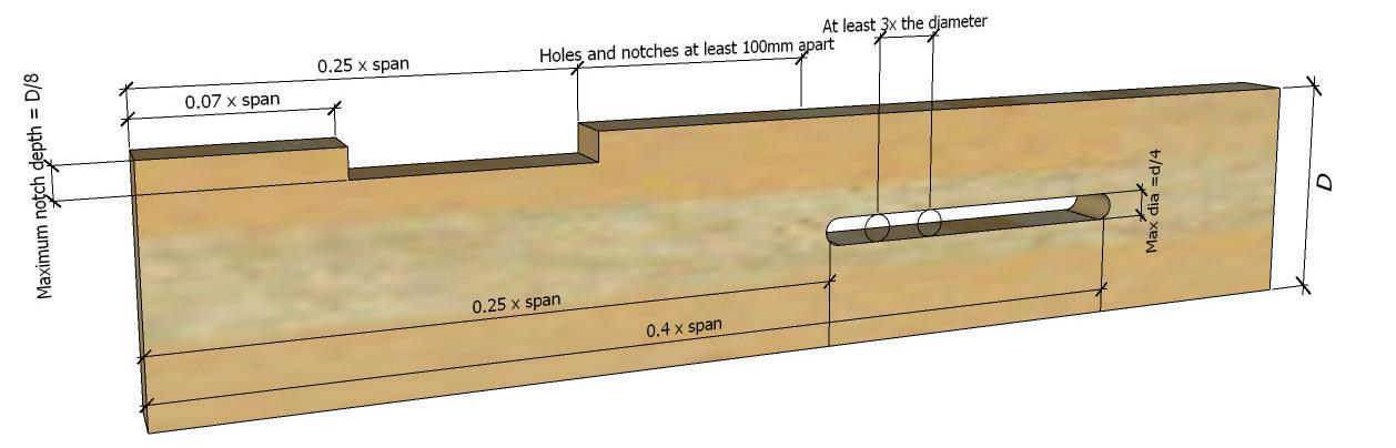
Notes: * distance given is when using maximum permissable hole size. If the joist depth is greater than 250mm, notch and hole sizes should not exceed those given for 250mm deep joist. If the joist depth is greater than 250mm, notch and hole sizes should not exceed those given for 250mm deep joists.
135
9.18
Depth of Joist *d* (mm) Max. Depth of Notch 0.125d (mm) Max. Diameter of Holes 0.25D (mm) Min. Distance between Holes* (mm) 100 12.5 25 75 125 16 31 93 150 19 37.5 112.5 175 22 44 132 200 25 50 150 225 28 56 168 250 31 62.5 187.5
136 Clear Span of Joist* (mm) Holes to be drilled only within the zones A-B (distance given is taken from either supporting walls in mm) Notches to be taken out only within the zones C-D (distance given is taken from either supporting wall in mm) A B C D 1.5 375 600 105 375 2.0 500 800 140 500 2.5 625 1000 175 625 3.0 750 1200 210 750 3.50 875 1400 245 875 4.00 1000 1600 280 1000 4.50 1125 1800 315 1125 5.00 1250 2000 350 1250 5.50 1375 2200 385 1375 6.00 1500 2400 420 1500 Notes: *Clear Span is the distance between supports A = 0.25 x clear span B = 0.40 x clear span C = 0.07 x clear span D = 0.25 x clear span 9.18
9.19 FLOOR DECKING
Floor Boarding
If floor boarding is used the following is acceptable:
Tongue and grooved softwood flooring with a minimum moisture content at the time of fixing to be between 16-20% and be in accordance with BS 1297. All boards must be nailed or screwed adequately, and the minimum thickness can be seen in Table.
9.20 PARTICLE BOARDING
Particle boards that are suitable for flooring are moisture resistant oriented strand board (OSB) or chipboard. If using chipboard this should be tongue and grooved and all joints glued and installed to the correct manufacturer’s details. It is advisable that all boards are mechanically fixed by screwing or nailing at 250mm centres. Where the board abuts the perimeter wall an allowance of 10mm should be made for
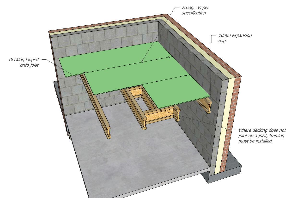
137
Softwood Floor Boarding - Minimum Thickness & Centres of Support Finished Board Thickness (mm) Maximum Joist Centres Typical Nail Fixing 15 450 45mm lost head nail 18 600 60mm lost head nail
Particle Floor Boarding - Minimum Thickness & Centres of Support Thickness (mm), Chipboard Thickness (mm) OSB Max Span Typical Nail Fixing (mm) 18 and 19 15 450 60mm annular ring shank 22 18 and 19 600 65mm annular ring shank 9.19
9.21 STAIRCASES
Stairways
The stairway should comply with Approved Document K of the Building Regulations in relation to the following:
• The pitch of the stair is to be no greater than 42°.
• To have a maximum rise of 220mm with a minimum going of 220mm.
• Headroom to be a minimum of 2m.
• The handrail should be placed 900mm to 1000mm from the pitch line.
• At its narrowest point, the minimum width of a winder tread should be no less than 50mm.
• The spindles from spindle to spindle must be no greater than 99mm.
• If glass is used this should meet the requirement of BS6206.
• Non domestic staircases should be engineered or third party verified
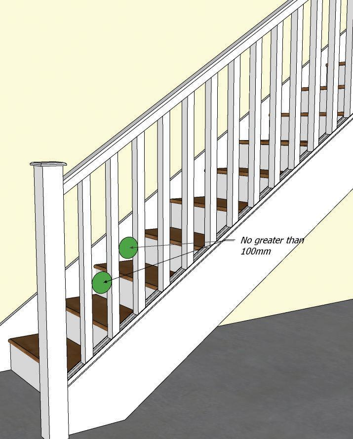
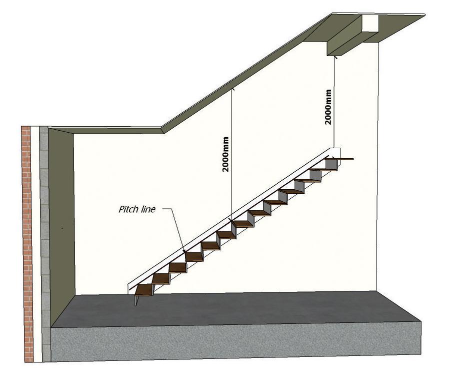
138 9.21
Type of Stairs Maximum Rise (mm) Minimum Going (mm) Private Stairs 220 220 Access Stairs 190 250 Common Stairs 190 250
9.22 INTERNAL WALLS
Internal Masonry Walls
Foundations
All load bearing internal masonry walls shall be constructed with a suitable foundation.
Compressive Strength
There are endless brick and block strengths with various levels of durability but as a minimum the adjacent table will provide a suitable level of structural strength, for the height of the proposed building.
Bonding and Tying
Bonding or tying an external wall to an internal wall is acceptable if a separating wall abuts an external wall they may be tied or bonded together if formed by using wall ties, an expanded metal strip, or equivalent fixings, at maximum 300mm vertical centres.
It is recommended that the builder follows the technical guidance produced by the manufacturer and complies fully with the installation technique.
139 9.22
Minimum Compressive Strength of Masonry Wall Height Minimum Compressive Strength of Brick or Block Unit One to two Storey Block 2.9N/mm2 Brick 9N/mm2 Lowest storey of a three storey wall or where individual storeys exceed 2.7m Block 7.5N/mm2 Brick 13N/mm2 Upper storeys of three storey wall Block 2.8N/mm2 Brick 9N/mm2
Wall Ties for Cavity Separating Walls
To ensure structural stability the two leaves of the cavity wall should be tied together following guidance in Approved Document A. Wall ties for timber structures should be installed in accordance with the system designer’s recommendations for timber framed separating walls.
Load-Bearing Timber Walls and Partitions
Any timber wall which is load bearing and forms part of the buildings structure shall be designed to ensure that the forces and loads applied to them are transferred through to the foundations. The wall shall be designed by a competent person and all structural timber shall be graded to strength class C16 or C24.
Partition walls in buildings are acceptable and can be formed from timber, steel or masonry. If these walls are structural, they must be pre-calculated by a competent person and have the necessary load bearing capacity, sound and fire resistance to carry out its function safely. Timber walls separating WC’s should have enough sound insulation applied within the studs.
Non Load-Bearing Timber Partitions
All non-load bearing partitions should be constructed in accordance with the requirement of regulation 7 of the manual to the building regulations by ensuring
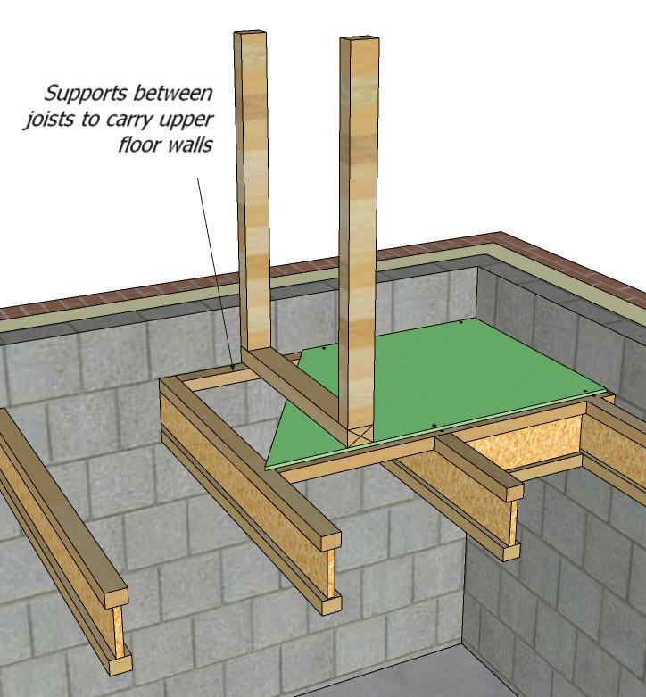
workmanship and quality is achieved, the wall should have sufficient bracing and strength and should achieve the following tolerances:
• The tolerance of horizontal straightness of a partition should be +/- 10mm over a 5m length;
• The deviation in vertical alignment of a partition in any storey height should be +/- 10mm;
Partition Walls on Flooring Systems
If partition walls are to be placed on the ground floor the floor must be designed to ensure that the additional weight can be suitably distributed. In the case of masonry this may require a foundation or thickening of the floor slab. In timber the sole plate must be adequately fixed to limit movement, each ground floor wall should have a DPC installed.
On first floor systems the timber boarding material shall be adequately fixed as per manufactures details and the wall placed to ensure that there is no movement.
Extra noggins or joists should be specified where stud partitions or proprietary plasterboard partitions are supported by a timber floor. There should also be some allowance for deflection of the floors at the head of partitions and it is recommended that these are mechanically fixed with screws.
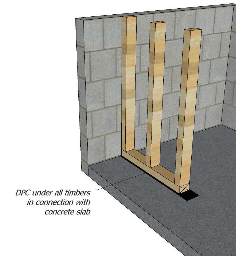
140
9.22
9.23 FIRE RESISTANCE
In dwellings 1/2 and 1 hours fire resistance should be achieved as a minimum, and the table below provides advice on how to achieve this requirement.
Plasterboard on Timber
Plasterboard Laminated Wall
board on both sides of frame
Two layers of 12.5mm board on both sides of framing or Proprietary fire boards (typically, 12.5mm-15mm) on both sides of framing
laminated on both sidesof 19mm board Refer to manufacturer’s recommendations
Note: reference to be made to manufacturer’s information i.e. British Gypsum, Knauf etc.
141 9.23
Fire Resistant Wall Specifications Material 1/2 hour FR 1 hour FR Brick 90mm Thickness 90mm Thickness Block 90mm Thickness 90mm Thickness
12.5
12.5mm
9.24 SOUND INSULATION
There is a requirement of Approved Document E ‘Resistance to the passage of sound’, that certain walls within the dwelling must meet the minimum standard of sound resistance. Walls and floors separating a WC must have the correct sound resistance. This can be achieved by the installation of mineral wool placed within the floor void and studs.
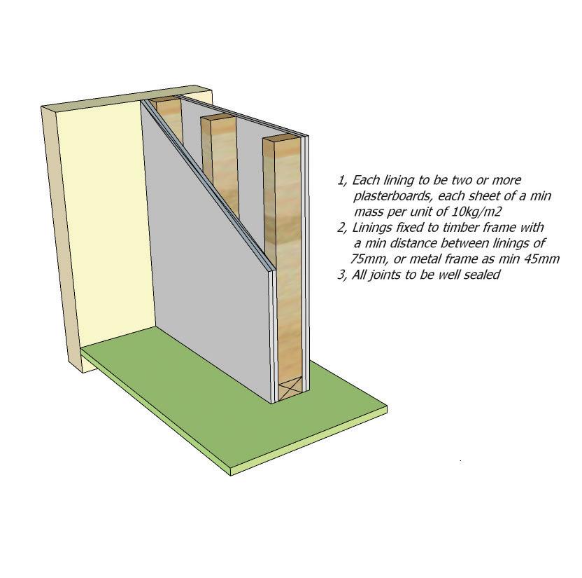
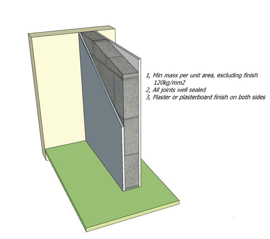
All separating walls in England and Wales may be built in accordance with Robust Details or Part E of the Building Regulations.
Sound insulation can be complied with by using either:
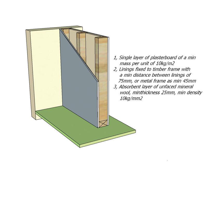
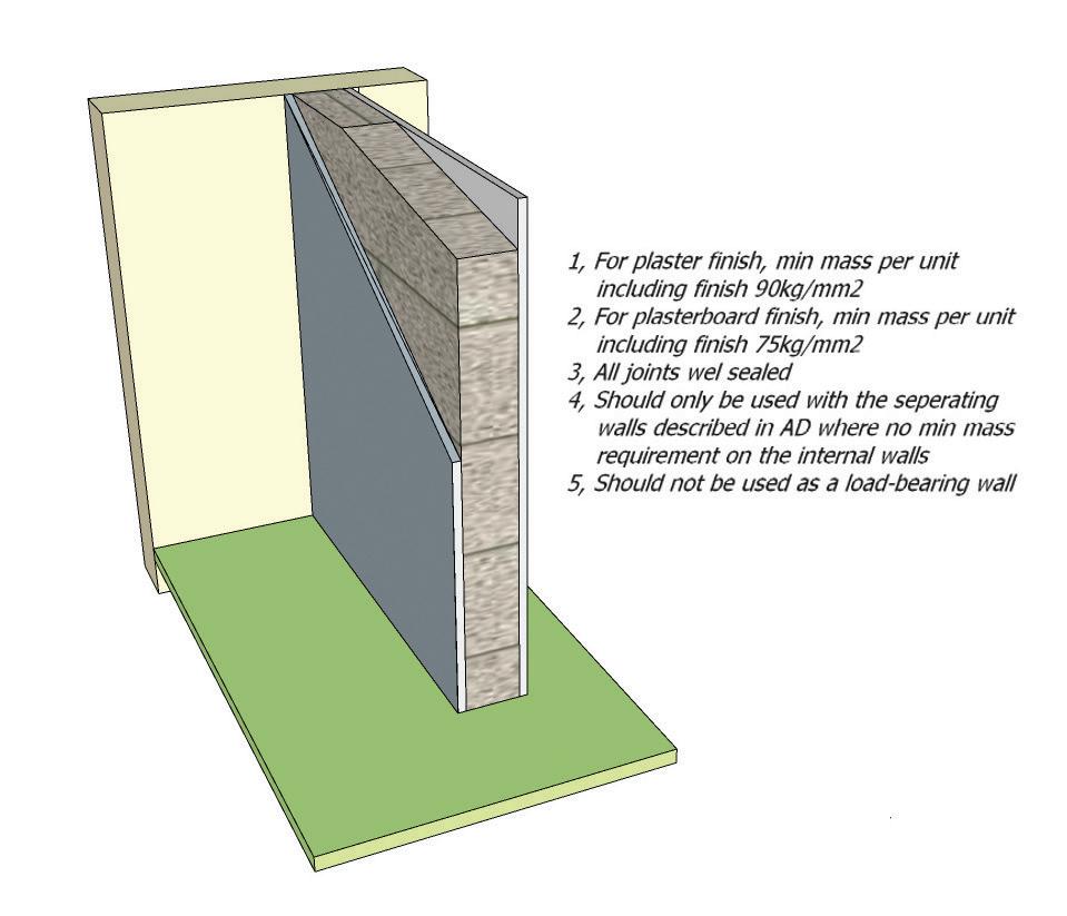
142 9.24
Internal Wall Type A – Timber or Metal framed Internal
Type B – Timber or Metal framed
Wall
Internal
Wall Type C – Concrete Block Wall
Internal Wall Type D – Aircrete Block Wall
9.25 PRE-COMPLETION TESTING
Pre -completion testing is required in the following situations:
• To all new build domestic properties (including rooms for residential purposes).
• Where the sound insulation construction is in accordance with the guidance given in Approved Documents of the Building Regulations.
• Where the building is not built in accordance with the Approved Documents of the Building Regulations.
• The requirements of the Robust Details system have not been met.
9.26 ROBUST DETAILS
As an alternative, builders can register with Robust details and construct to their specification and eliminate the need for pre-completion testing.
Robust Details Limited
Block E
Bletchley Park Science and Innovation Centre
Milton Keynes
Buckinghamshire
MK3 6EB
www.robustdetails.com
143 9.25
9.27 CHIMNEYS
If a chimney is not provided with adequate support by ties or securely restrained, its height (measured to the top of the chimney) should not exceed 4.5 x its least horizontal dimension, when measured from the highest point of intersection with the roof surface (density of masonry must be minimum 1500kg/m3 (see diagram below).
Chimneys and Flues
Ensure that all gas flues terminate to the open air i.e.. Flue blocks must terminate at an appropriate ridge vent or similar even where no appliance is fitted prior to the sale/occupancy of the property.
Special blocks are made to accommodate gas fire flues which tend to be slightly thicker than normal units. When used in external walls, care should be taken not to reduce the clear cavity width below 50mm. Typical chimney positions, dpc and flashing details are shown in diagrams adjacent.
Ensure that:
• A 50mm cavity at the back of the chimney breast is maintained to prevent rainwater penetration
• Flue liners are used as specified with sockets upper most and jointed with fire resisting mortar
Corrosion of Lead Work
When free lime from mortar comes into contact with lead trays or flashings, (due mainly to the continual saturation of the brickwork) in areas such as chimneys, the lead should be protected from corrosion by the use of a thick coat of bitumen paint covering the faces likely to be in contact with the mortar. The protection against corrosion of lead work buried in mortar, is suggested in guidance given out by the Lead Sheet Association. This treatment can also reduce staining of lead and brickwork. It is unnecessary to treat flashings buried only 40 – 50mm into mortar joints (cover flashings), as this close to the drying surface carbonation of free lime is rapid and there is no risk of corrosion in such circumstances.
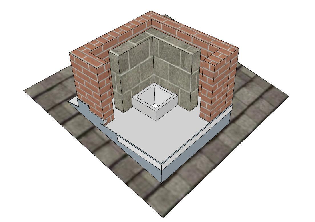
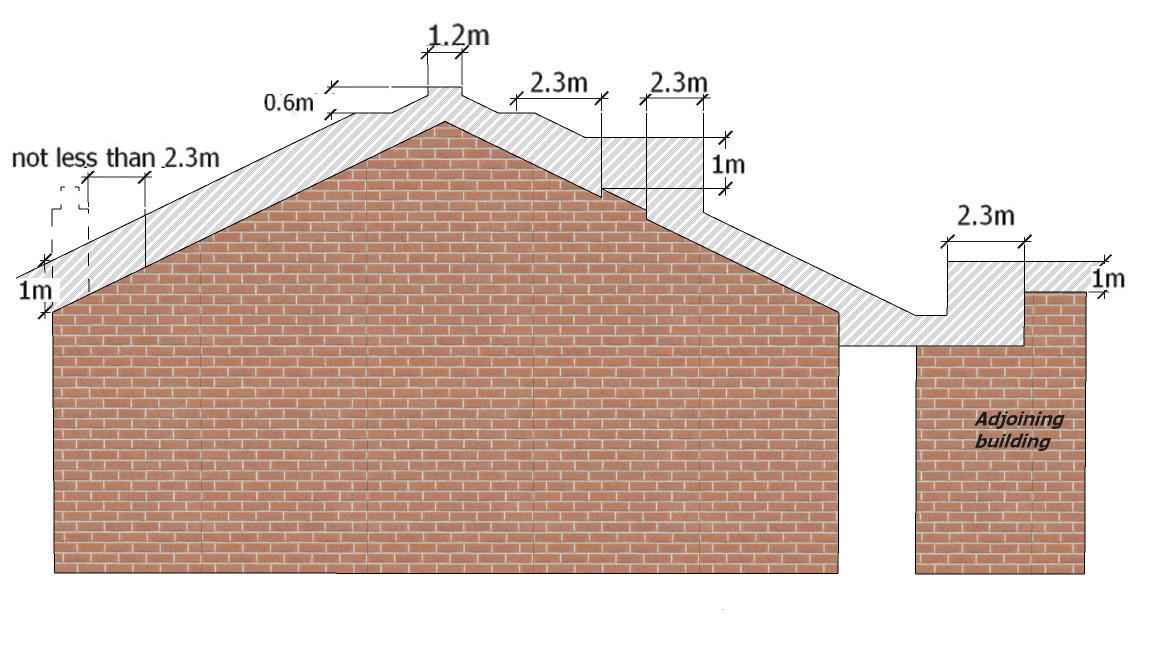
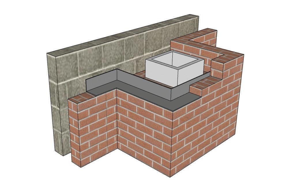
144 9.27
Chimney Tray, Low Level
Required at low level where a cavity-walled chimney with brick shoulders is built on to an external wall; the tray prevents water which may enter the shoulders from penetrating to the inner leaf of the wall (see diagram below).
Material: 1mm aluminium alloy sheet to BS EN 485-2: 1995 ‘Aluminium and aluminium alloys. Sheet strip and plate. Mechanical properties’. This has a higher melting point than lead, so is suitable for installation close to a heat source.
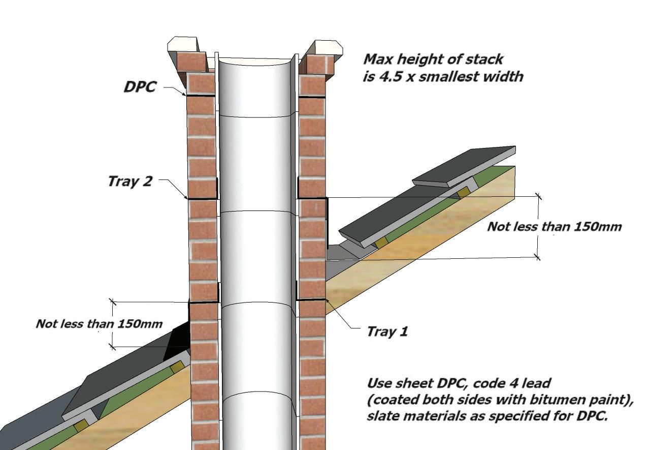
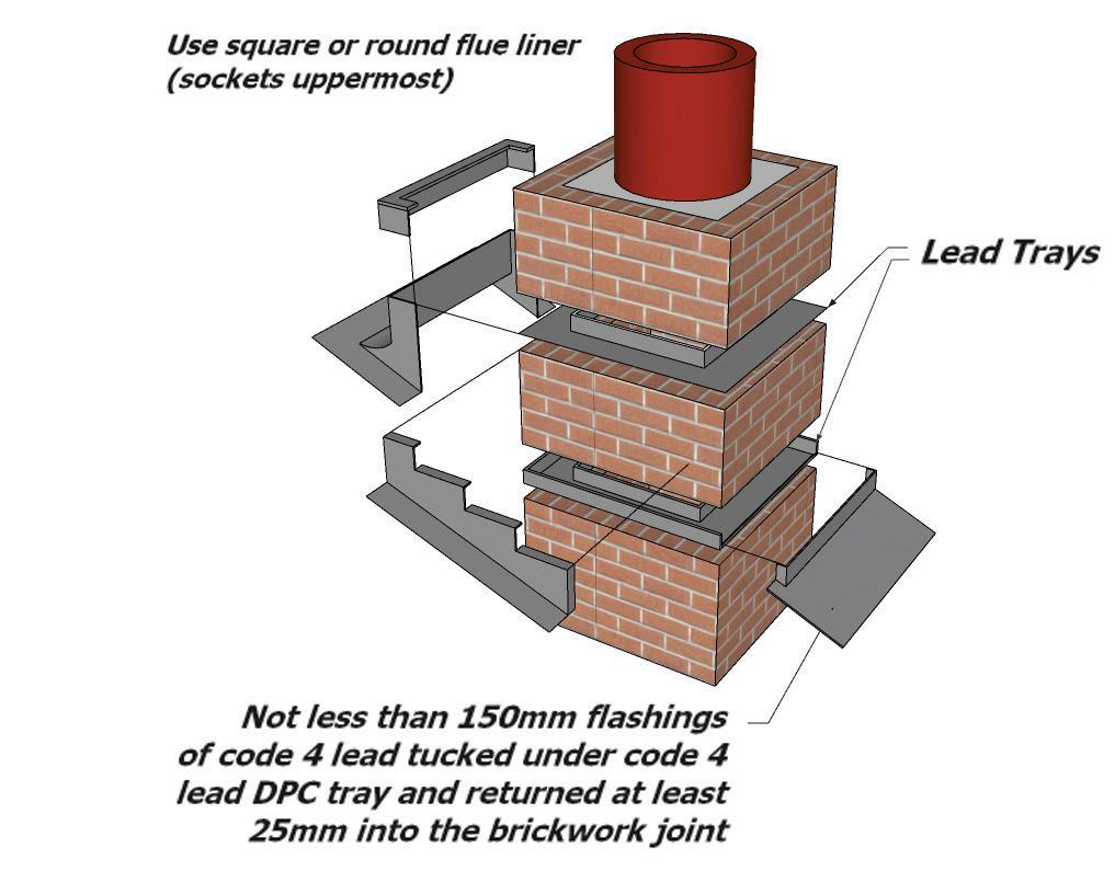
Chimney Tray, High Level
Required to prevent the entry of water at high level where a chimney rises through a pitched roof; suitable for newbuild or remedial work. Minimises disturbance to surrounding construction in remedial work. Material: Lead sheet to BS 1178: 1982 ‘Specification for milled lead sheet for building purposes. Code 4 as standard. Standard sizes: 800 x 800mm, 900 x 900mm, 950 x 950mm. To suit either 195mm square or 195mm diameter circular flue.
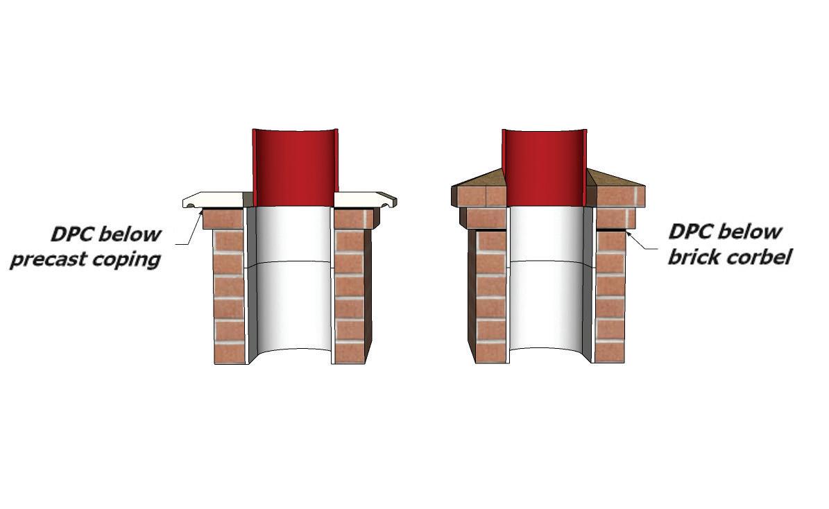
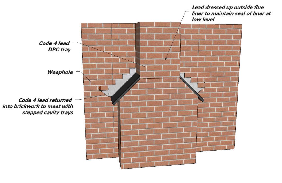
145 9.27
146
147
CLADDING CLADDING
10.0
10.0
10.0 INTRODUCTION
Wall cladding presents a hazard if it becomes detached from the building and may cause structural failure and water ingress. An acceptable level of safety can be achieved by different means depending on the type and location of the cladding. This relates to all forms of cladding, including curtain walling and glass facades. Further guidance on the acceptance and viability of wall claddings can be sought on the Building regulations for England & Wales, Scotland and N.Ireland, guidance concerning the weather resistance of wall cladding is included in Approved Documents, site preparation and resistance to moisture, or guidance on resistance to spread of fire, fire safety, or guidance in relation to sound insulation and resistance to the passage of sound.
The cladding will meet the safety requirements if:
• The cladding is capable of safely sustaining and transmitting to the supporting structure of the building all dead, imposed and wind loads.
• The cladding is securely fixed to and supported by the structure of the building. This shall comprise both vertical support and horizontal restraint.
• Provision is made, where necessary, to accommodate differential movement of the cladding and the supporting structure of the building.
• The cladding and its fixings (including any support components) are of durable materials; the design life of the fixings being not less than that of the cladding. Fixings shall be corrosion resistant and of a material type appropriate for the local environment.
• The cladding is resistant to penetrating and driving rain.
• The cladding is resistant to fire spread as per the guidance noted.
Wind Loading
Wind loading on the cladding should be derived from BS 6399, Part 2: 2001 with due consideration given to local increases in wind suction arising from funnelling of the wind through gaps between buildings. Guidance on funnelling effects is given in BRE Digest 436 Wind loading on buildings - Brief guidance for using BS 6399-2: 1997 available from BRE.
Where the cladding is required to support other fixtures and fittings (e.g. handrails and antennae), account should be taken of the loads and forces arising from such fixtures and fittings.
Fixings
The selection of fixings for supporting cladding should be fully compliant with the latest Buildings Regulations and fully compliant with the manufacturer’s installation guidelines and any third-party accreditation or approvals.
148
10.1 TIMBER BOARDING
Timber boarding should be at least 16mm thick and allowance for moisture movement in boarding should be made by making tongues, joints or overlaps at least 10% of the board width.
Timber boarding should be battened off the supporting background to provide a minimum 19mm cavity for draining and venting.
Battens should be a minimum 38mm wide, preservative treated and at maximum 600mm centres. A breather membrane should always be installed when horizontal battens are located against the sheathing. Battens on timber frame should be fixed to each stud (and not to the sheathing) with annular ring nails of length at least twice the batten thickness plus the sheathing thickness (or plain shank nails of length 2.5 times the batten thickness plus the sheathing thickness).
Boards should be fixed to battens by face or secret nailing annular ring nails at least twice the board thickness or plain shank nails at least 2.5 times the board thickness. Butt joints at board ends should occur at battens. Nails should be either hot dipped galvanised, stainless steel or equally durable. Aluminium nails should not be used with copper containing preservative treated timber and galvanised nails should not be used with western red cedar.
Ends cut on site should be dipped or liberally brushed with preservatives.
Claddings fixed directly to frame.
Avoid the following defects:
• Insufficient overhang of roof at verges to protect timber.
• Battens fixed directly to sheathing
• Movement or slipping of timber cladding.
• Insufficient provision for cladding around openings, restrict windows and doors from opening.
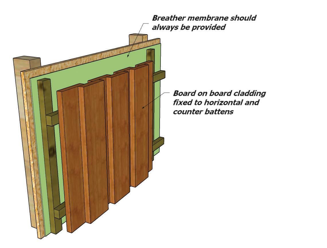
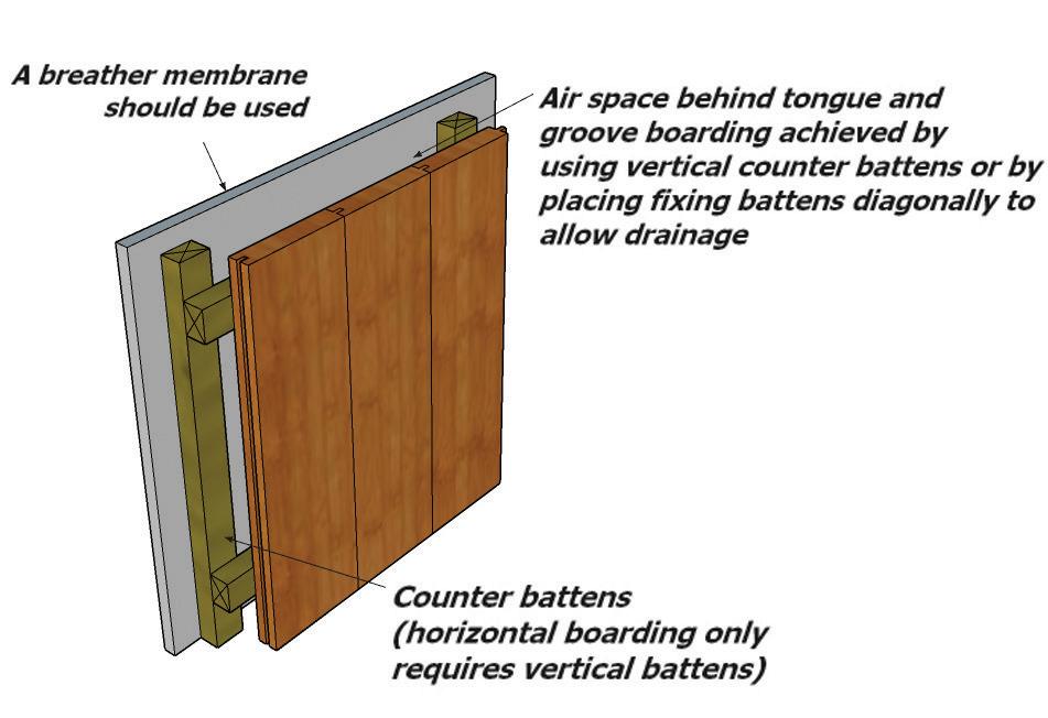
149
10.1
Timber and boards for exterior use should be of a durable species, with sapwood excluded, or preservative treated by pressure impregnation using preservatives suitable for use in hazard class 3 in compliance with BS8417:2003, or equivalent.
150
Hardwoods Softwoods Preservative Treatment Afrormosia Western Red Cedar Not Required Afzelia Not Required Iroko Not Required Keruing Not Required Mahogany, African Not Required Oak, European Not Required Opepe Not Required Sapele Not Required Teak Not Required Utile Not Required Abura Douglas Fir Required Elm Hemlock, Western Required Meranti Larch, European Required Larch, Japanese Required
(European) or Scots Pine Required Sitka Spruce Required
or European Spruce Required 10.1
Redwood
Whitewood
Plywoods
European Birch or Birch Faced Plywood (WBP) Required
European Softwood Plywood (WBP) Required
North American Douglas Fir or Douglas Fir Faced Plywood (Exterior Grade) Required
North American Softwood Plywood (Exterior Grade) Required Gabon or Mahogany Plywood (WPB) Required
Marine grade plywood specified in accordance with BS 1088 but excluding Gabon Not Required
Typical preservatives are those conforming to the requirements of BS EN 599-1:1997 for hazard class 3, for example micro emulsions or copper organic pressure impregnated.
151
10.1
10.2
10.2 TIMBER
Boarding to be preservative treated, minimum 16mm thick and sufficient tongues or overlaps provided to permit shrinkage and expansion of the timber.
Timber boarding should be battened off the sheathing to provide a minimum 19mm cavity for draining and venting.
Battens should be a minimum 38mm wide, preservative treated or equivalent hazard class 2 and at maximum 600mm centres. Battens should be fixed to each stud (and not to sheathing) with annular ring nails of length at least twice the batten thickness plus the sheathing thickness or plain nails of length at least 2.5 times the batten thickness plus the sheathing thickness. All nails to be fixed at 600mm centres.
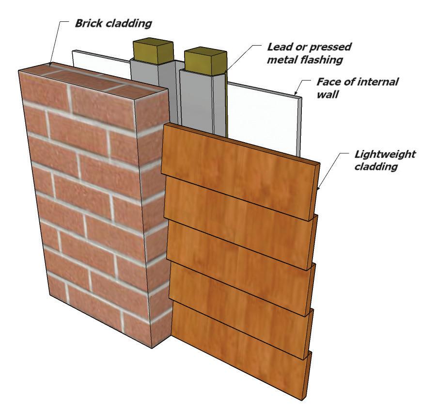
Counter Battens Should be Used for Vertical Cladding
Boards should be fixed to battens by face or secret nailing with annular ring nails at least twice the board thickness or plain shank nails at least 2.5 times the board thickness. Butt joints at board ends should occur at battens. Nails should be either hot dipped galvanised, stainless steel or equally durable. Aluminium nails should not be used with copper containing preservative treated timber and galvanised nails should not be used with western red cedar.
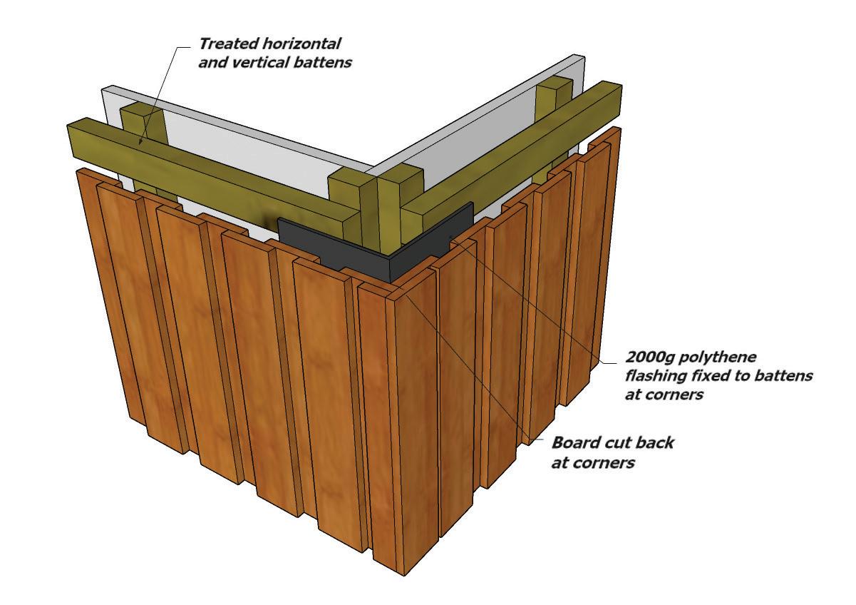
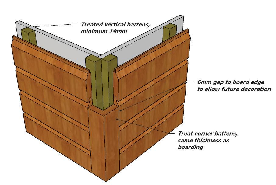
152
10.3 PLYWOOD
Plywood sheets used as cladding should be pressure preservative treated, a minimum 12mm thick and bonded with WBP or equal quality exterior adhesive and marked accordingly. Battens should be vertical and treated. Joints between sheets should be made resistant to excessive water penetration by fixing cover battens or flashings.
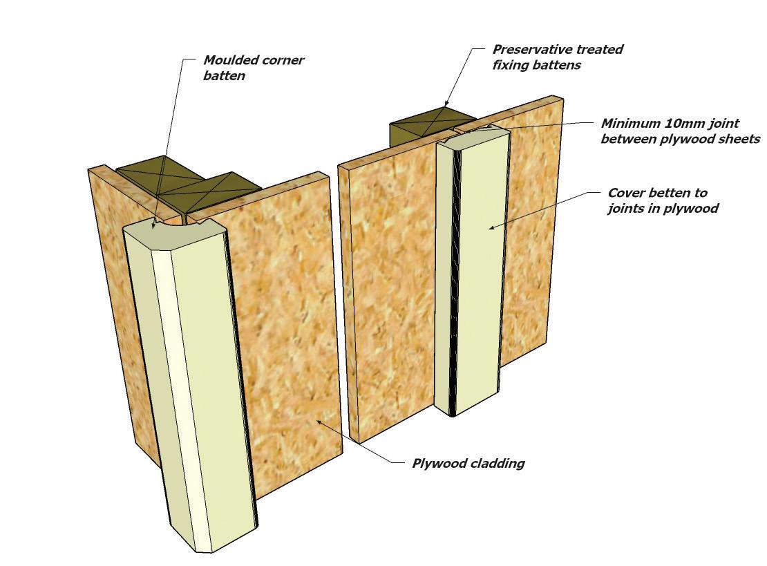
10.4 TILE AND SLATE CLADDING
• Tile or slate cladding should be fixed in accordance with the manufacturer’s recommendations.
• Battens should be a minimum 38 x 25mm for stud centres up to 600mm, and should be preservative treated (BS 8417, or equivalent, hazard class 2). 38 x 19mm counter battens should be provided on severely exposed sites. Severely exposed sites are those shown on the wind driven exposure map contained on page 119.
• Battens should be level and fixed to each stud (not to sheathing) with annular ring nails of length at least twice the batten thickness plus sheathing thickness or plain nails of length at least 2.5 times the batten thickness plus the sheathing thickness.
• Battens should not normally be less than 1200mm in length and span across at least 3 supports.
• Nails should be either hot dipped galvanised, stainless steel or equally durable.
• A breather membrane (not a roof underlay) should normally be fixed to the sheathing behind the battens.
• Edge of hanging tiles should be cloaked at the jambs of all openings with purpose made corner tiles or by butting against a timber reveal with drainage channel behind.
153
10.3
10.5 OTHER CLADDINGS
Other cladding should only be used if they either:
• Conform with a British Standard and, where appropriate, are detailed for use with timber frame construction by the manufacturer.
• Approved as being suitable by an independent assessment authority.
• In addition, they should be approved by ICW.
10.6 WEATHER RESISTANCE OF WALLS AND CLADDING
Existing solid brick or stone walls may be acceptable as a weather resisting wall subject to the exposure category of the building (see exposure to wind driven rain map) and the porosity of the masonry. It is anticipated that all buildings located in severe or very severe locations will require at least one of the additional treatments noted below. However, all solid masonry wall situations will require a specialist’s report to identify the extent of any necessary remedial treatment.
The specialist report including the proposed design and/or the manufacturer’s details must be forwarded to ICW for approval along with other requested reports that form part of the conditions placed on the warranty.
10.7 EXTERNAL TREATMENTS
Existing cladding can be retained if it can be shown that:
• The system is maintaining the integrity of the building.
• It is adequately fixed and the expected life span of the fixings where appropriate is in excess of 15 years.
• The cladding material is free from and defects.
• Adequate provision for movement has been allowed.
• If the above situations cannot be satisfied, then a new external cladding or rendering system will need to be installed.
154 10.4
10.8 INTERNAL TREATMENTS
An alternative to preventing moisture penetration by using externally applied claddings and renders is internally applied methods.
Systems are available that are installed on the inside of existing walls to prevent moisture penetration reaching the internal accommodation. These include:
• Independent metal or timber framed systems. These should not be fixed to the existing masonry walls but fixed at the ‘head and base’ to avoid direct contact. Ventilation should be provided to avoid build-up of condensation between the masonry and the inner lining system.
• Impervious sheet and drained sheet systems. Systems to prevent water penetration should be installed in accordance with the manufacturer’s recommendations and should have third party accreditation acceptable to ICW. i.e. BBA Certification.
10.9 INTERSTITIAL CONDENSATION
Vapour control layers may need to be incorporated on the warm side of the thermal insulation. Voids and cavities may also need to be ventilated.
10.10 SURFACE CONDENSATION
Under certain conditions the warmth from sunlight falling onto damp solid masonry wall can drive moisture inwards and form condensation on the outside of a vapour barrier.
10.11 CONTROL OF MOISTURE PENETRATION
Measures should be taken to ensure that thermal insulation in cavities does not encourage the passage of damp from the ground or from the exterior of the building to the inside of the building.
155 10.6
10.12 THERMAL INSULATION OF WALLS AND CLADDINGS
Various methods exist to upgrade the thermal insulation of existing walls and floors. Regardless of the methods adopted, it is essential that risks associated with increased thermal insulation are minimised, including:
• Surface condensation caused by improvements to draught proofing of the building.
• Interstitial condensation caused by moisture laden air passing from a dwelling to within the fabric of the structure and condensing on cooler surfaces.
• Increased risk of damp penetration caused by filling of cavities with insulation.
• Maintaining the robustness of the external and internal wall surfaces by the provision of adequate mechanical protection over insulation materials, e.g. externally applied insulation systems with render coat mechanical protection.
• Avoidance of cold bridges around openings and when structural elements extend through thickness of the building envelope.
• Where planning restrictions prevent the thermal upgrade of the building then ICW may deem it appropriate to add an endorsement to the policy regarding the risk of condensation.
It should be noted that these diagrams are for upgrading thermal values but are not always to prevent moisture penetration.
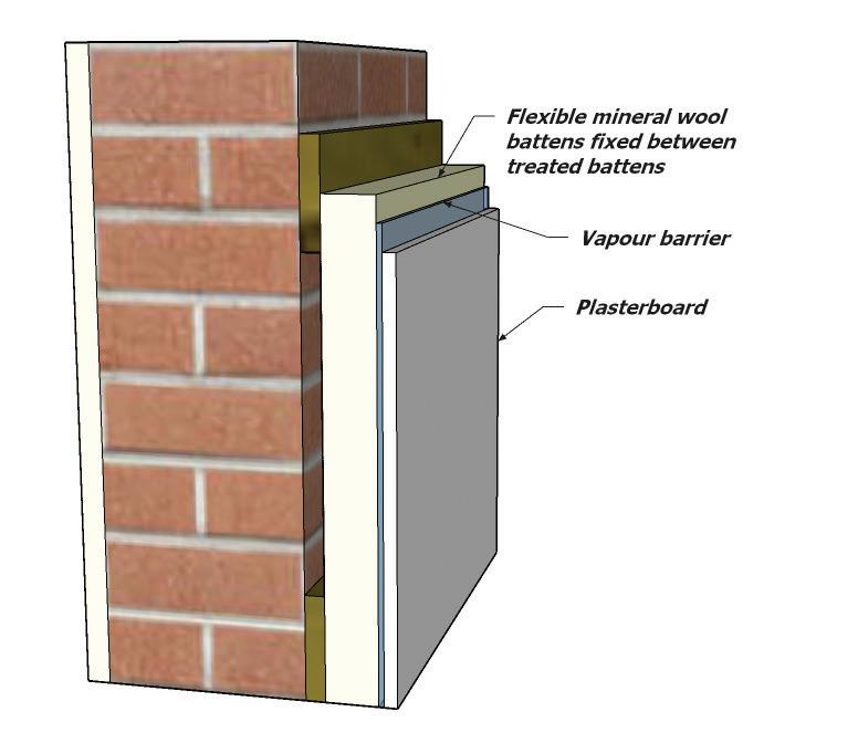
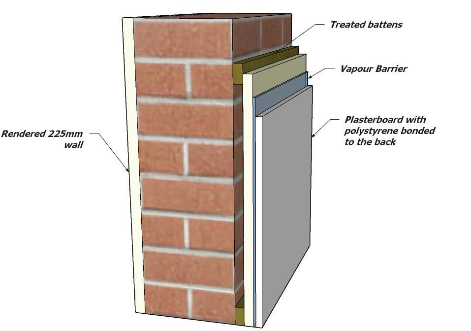
156 10.12
10.13 RENDER
Render failures are generally due to poor workmanship, inadequate preparation of substrates, poor detailing or inadequately trained personnel applying the render or failing to follow the correct render specification by using alternative inappropriate / substandard materials or mix ratios.
Render is generally not considered ‘waterproof, therefore water seepage can be expected through the render to the substrate / cavity. The render is only considered as contributing towards the ‘weather resistance’ of an external wall and not considered as providing an impermeable cladding. Therefore, all substrates must be constructed to prevent moisture reaching the internal finishes.
All substrates must be in a sound condition and be suitable to receive the render. A substrate should not consist of differing material e.g. concrete blockwork with clay facing bricks. Render carrier boards to have third-party accreditation acceptable to ICW.
Abutments between cement render and other cladding materials or components should be weathertight and allow for differential movement.
• Any joints in the wall where movement may occur should be continued through the rendering.
• An appropriate, flexible, mastic sealant in accordance with manufactures’ recommendations to be used to complete movement and abutment joints, enabling a sealed joint to prevent moisture ingress.
• Render should not bridge the dpc and be finished onto a durable render stop.
• All render must comply with BS EN 998-1:2006 for the specification of render and BS EN 13914-1:2016 for the design, preparation and application of external rendering.
• Exposure zones and type of wall construction to be considered:
- Minimum 15mm cement render thickness with a partial fill cavity.
- Minimum 20mm cement render thickness with a full fill cavity.
• Sand for rendering should be stored separately from other building and concreting sands.
• Additives should not be used unless specified, and then only in accordance with manufacturer’s recommendations.
• Site made render solutions will not be acceptable on projects where the render is to be applied on the following substrates:
- Render board.
- Render carriers.
- Hollow clay brick/block units.
- Insulated Concrete Formwork (ICF).
• Proprietary render systems with third party accreditation acceptable to ICW to be used in accordance with the manufacture’s recommendations in particular application to the correct substrate intended for by the third-party certification.
• For ICW warranty purposes:
- All externally rendered cavity walls (masonry outer and inner leaves, or masonry outer and framed inner structures) must be provided with a suitable cavity tray, stop ends and weep vents over all external wall openings, flashing abutments and horizontal cavity barriers. Weep vents must be provided and must not be blocked/covered over by the render.
- ICW will accept the omission of weep holes when a proprietary render system is used and is not a requirement of the render manufacturer. However, if weep holes are required for the ventilation and drainage of timber frame structures then they must be installed and subsequently not be blocked or covered by render.
157
10.13
Protection of Render
Renders are vulnerable to damage through exposure to extremes of temperature during the first few days. Therefore, the following appropriate precautions should be arranged in advance:
• In hot weather, the wall should be shaded from the direct heat of the sun or the work programmed to be carried out in the shade.
• In cold weather, rendering should not be attempted when there is a risk of frost occurring during the day or the following night.
• Air temperature should be at least 5oC at the time of application.
• When rendering has been applied, it should be prevented from drying out for two or three days until the mortar has hardened or in accordance with manufacturer’s curing times.
• In drying winds, it may need to be kept damp by gentle spraying. Proprietary rendering products to be applied in accordance with manufacture’s recommendations.
Timber frame background
A drained and vented cavity should be provided behind cement render on timber framed construction. Mesh or metal lathing should be one approved by an independent authority and fixed to vertical battens at stud centres. The minimum size of the cavity should be 19mm when the mesh or metal lathing is backed by a water-resistant membrane and 50mm when the mesh or metal lathing is unbacked. A dpc should be provided between unbacked render and timber battens.
The carrier system must be stainless steel in accordance with EN 10088-1 (Austenitic steel) or zinc coated steel in accordance with EN ISO 16120-2 and EN 10346. Where sited in a coastal location a higher grade A4 stainless steel should be used.
Battens should be either 25 x 38mm or 50 x 50mm, preservative treated and fixed at spacings recommended in BS EN 13914-1:2016.
Fixings and preservatives should be compatible. Battens should be fixed to each stud with annular ring nails of length at least twice the batten thickness plus the sheathing thickness. Nails should be hot dipped galvanised, stainless steel or equally durable.
Where cavity barriers are required, they should be correctly fitted in accordance with relevant fire testing without gaps; fill the cavity and be under compression and be fixed with stainless steel staples or equally durable fixings.
Where cement render spans across an intermediate floor zone in timber frame construction, allow for differential movement due to timber shrinkage by incorporating a movement joint. Vertical movement joints should also be provided at maximum 5m horizontal centres.
It should be noted that ICW will accept ‘no cavity’ for proprietary render systems. The design will be assessed on individual merit with also the following criteria to be met:
• Third party accreditation of the render system, appropriate for timber frame and acceptable to ICW.
• Interstitial condensation assessment.
• Breather membrane to not only be lapped but taped with the breather membrane manufacturer’s tape.
• A suitable EDPM to be installed around all external frames and penetrations through the external timber frame envelop.
• The base of the substructure at ground level to be drained with weep holes at 1.35m centres.
158 10.13
Masonry background
Walls should be examined for excessive moisture content prior to rendering. This is particularly important where the masonry background has no upper limit on its soluble salts content.
Parapets, chimneys, retaining walls and walls below dpc level with this background should employ sulphate resisting cement in the render and mortar.
Angles, stop beads and jointing sections should be secured with drilled or shot-fired fixings; proprietary adhesives to manufacturer’s recommendations and not with gypsum plaster.
Check whether the rendering can be applied directly onto the wall or whether any preparatory treatment is required in accordance with the manufacturer’s instructions. The surface should be checked for suction by dampening the wall with clean water.
Application
The undercoat should be built up to the correct thickness in two or more stages without any appreciable delay and ruled off with a straight edge between the grounds.
The undercoat should be finished with a wood or plastic float and, unless otherwise required, combed to divide the surface into small areas to provide a key for the final coat. The undercoat should be allowed to dry before application of the next coat.
The final coat should be applied in a single, continuous operation over each wall. The position of any joints in the final coat should be determined in advance.
Where additives are used, the recommendations of the manufacturer should be followed.
Metal lathing should be fixed in accordance with the manufacturer’s instructions.
Precautions should be taken to prevent rapid drying out of wet applied materials by:
• Dampening porous supporting surfaces
• Providing sun screens across window openings in hot weather.
Application of proprietary render systems in accordance with the manufacture’s recommendations. Renders below dpc:
• The horizontal DPC must form a break in the render system with the use of either stop beads or bell-cast bead.
• Renders used below the DPC will only be considered:
- If sulphate resisting cement is used or
- If a proprietary render system is used the manufacturer provides a site-specific specification for this.
- Renders/boards to be used within 150mm of the adjacent ground level, to have third party approval for use in this location.
159 10.13
160
10.13
Render finish at DPC level
10.14 FURTHER
GUIDANCE
The use of large panels of glass in cladding of walls and roofs where the cladding is not divided into small areas by load bearing framing requires special consideration. Further guidance is provided in the following documents:
UK Guidance –BBA website www.bbacerts.co.uk
The Institution of Structural Engineers’ Report on ‘Structural use of glass in buildings’ dated 1999, available from 11 Upper Belgrave Street, London SW1X 8BH. ‘Nickel sulfide in toughened glass’ published by the Centre for Window Cladding and Technology dated 2000.
Further guidance on cladding is given in the following documents -
The Institution of Structural Engineers’ Report on ‘Aspects of Cladding’ dated 1995.
The Institution of Structural Engineers’ Report on ‘Guide to the structural use of adhesives’ dated 1999.
BS 8297 Code of practice for the design and installation of non-load bearing precast concrete cladding.
BS 8298 Code of practice for the design and installation of natural stone cladding and lining.
Additional guidance on fixings is given in the following documents - ETAG No. 001 1997 Guideline for European Technical Approvals of Metal Anchors for use in Concrete, European Organisation for Technical Approvals, (EOTA) Brussels. All EOTA parts may be downloaded in English from www.eota. be. English version published by the British Board of Agreement.
- Part 1 Anchors in General
- Part 2 Torque Controlled Anchors
- Part 3 Undercut Anchors
- Part 4 Deformation Controlled Anchors
- Part 5 Bonded Anchors
- Part 6 Metal anchors for redundant use in concrete for lightweight systems.
- BS 5080 Structural fixings in concrete and masonry Part 1 1993
- CIRIA Report RP 566 Cladding Fixings: Good practice guidance
- CIRIA Reports C579 and C589 Retention of masonry facades - Best practice guide.
- Guidance Notes published by the Construction Fixings Association
- Guidance Note: Procedure for Site Testing Construction Fixings (1994)
- Guidance Note: European Technical Approvals for Construction Fixings (1998)
- Guidance Note: Anchor Selection (1995)
- Guidance Note: Fixings and Fire (1998)
- Guidance Note: Anchor Installation (1996)
- Guidance Note: Bonded Anchors (1999)
- Guidance Note: Heavy Duty Expansion Anchors (1997)
- Guidance Note: Fixings for Brickwork and Blockwork (1997)
- Guidance Note: Undercut Anchors (1998)
- Guidance Note: Fixings and Corrosion (2002)
Following the latest consultation of cladding and fire risk assessment, we would expect all cladding materials to also meet the following new British Standards once the policies and standards have been fully confirmed.
BS 8414-1. Fire performance of external cladding systems. Part 1. Test method for non-loadbearing external cladding systems applied to the masonry face of a building.
BS 8414-2. Fire performance of external cladding systems. Part 2. Test method for non-loadbearing external cladding systems fixed to and supported by a structural steel frame.
BS 9414. Fire performance of external cladding systems. The application of results from BS 8414-1 and BS 8414-2 tests.
161 10.14
162
163
ROOF
11.0
11.0 ROOF
Statutory Requirements
Building Regulation Requirements
Any roofing structure should be suitably designed by a competent person and the calculations provided to evidence that they meet the requirement of Approved Document A of the Building Regulations. All roofing systems are exposed to loadings and forces and they must be constructed in a manner that distributes these to the ground. It is important to follow the guidance set in Approved Document A.
Workmanship
During the construction phase:
• All workmanship must be completed in a competent workmanship like manner.
• Protected against unnecessary damage.
• Design and Installation specifications are followed.
• Products and materials are inspected for suitability for their purpose.
Materials
All materials used shall:
• Be adequately protected and stored in a correct manner.
• Comply with relevant British Standards or equivalent European Technical Specification with the certification available for inspection by ICW.
• Be installed as per Manufacturers details.
• Have a life span of 60 years when used as part of the structure, however it is accepted that materials that are not an integral part of the structure may require maintenance and or replacement within this period.
Design
Where a specialist design is requested or required, they shall:
• Be designed by a suitably qualified person.
• Be supplied with clear precise instructions.
• Be supported with structural calculation when outside the guidance of the Approved Documents.
• Be available for inspection by ICW.
164
11.0
11.1 BRACING AND RESTRAINT
The building roof shall be constructed so that the combined dead, imposed and wind loads are sustained and transmitted by it to the ground safely; and without causing such deflection or deformation of any part of the building, or such movement of the ground, as will impair the stability of any part of another building.”
Wind Loading
For the roof to withstand forces applied through wind loading the construction of the roof should be calculated by a competent person and installed following the manufacturer’s installation guide. The roof should be suitably restrained as shown in Approved Document A of the Building Regulations. Generally, roofs are secured by fixing of a timber wall plate on a bed of mortar. This wall plate requires fixing to the internal wall by way of holding down straps spaced at a maximum of 2 m and mechanically fixed with screws.
Securing of roofs to the supporting structure roof timbers are normally supported on a timber wall plate or similar, which should be levelled using a spirit level so that loadings from the roof are directed perpendicularly down the supporting wall. There is also a requirement to ensure that holding down straps are provided in areas of severe wind exposure where required by the roof design and these should be installed subject to structural engineers’ details.
165
11.1
Bracing and Fixing
To ensure the roof is adequately braced, it is recommended that the roof is secured to the gable wall this can be done by using a 100mm x 25mm timber, twice nailed to roof timbers using 65mm long, 3.35mm diameter galvanized wire nails. The installation of the roof should also have incorporated diagonal and longitudinal bracing, this will form part of the structural design of the roof truss and be installed as per engineers’ details.
Lateral Restraint Straps
Roofs should provide lateral restraint to all walls running parallel to them, by means of 30mm x 5mm galvanized or stainless-steel restraint straps at 2m centres. These restraint straps should be bridged between or below the trusses/rafters and must span over three trusses/rafters. Further guidance can be found in Approved Document A.
Loft Hatch Provision
In most cases here will be a service loft hatch placed within the roof structure, it is the responsibility of the roof designer to ensure the bracing to the loft opening adequately meets the additional loads placed upon it. Also, the hatch itself must be thermal efficient and have adequate fire protection to achieve the requirements of Approved Document L and B.
It is common practice that water storage tanks are located within the roof space. It is the responsibility of the roof designer to ensure the roof truss can accommodate the extra loading and the material used to support the tank i.e. chipboard or floor boarding is suitable for its intended purpose. Alternatively, the installation of joist hangers built into the walls with joists spanning to facilitate a storage tank may be used this is however subject to structural engineer’s design.
166
11.1
11.2 FIRE STOPPING
Fire Stopping and Compartmentation
The use of compartmentation enables the roof space to be sub-divided to restrict the spread of fire. It is advisable that the roof compartment should have the following design elements to ensure the spread of fire complies with that of approved Document B. This will be achieved by the installation of cavity barriers at:
• Within boxed eaves at separating wall position.
• Junctions of separating wall and external cavity wall.
• Junctions of compartment wall and compartment floor.
• Junctions of separating wall with roof, under roof tiles.
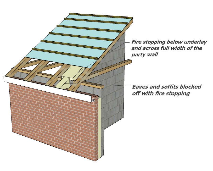
Junctions of Compartment Walls with Roof
There is always the possibility that a fire could penetrate into the roof void and spread externally to the adjacent compartment, to reduce this risk it is advisable that either side of the roof there is a zone of 1500mm wide on either side that has a covering designated AA, AB or AC on a substrate or deck of a material of limited combustibility.
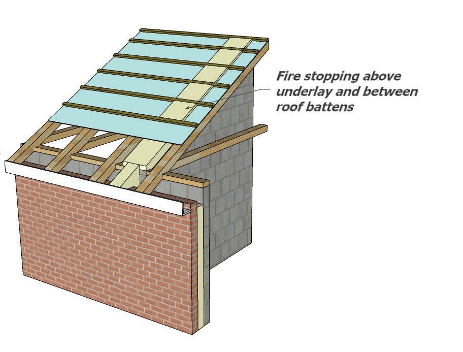
167
11.2
11.3
SPANDREL PANELS
A spandrel panel is a factory produced, prefabricated, structural panel. They are used as a separating wall or in place of a traditional external gable block wall enveloping a cold roof space used in conjunction with trussed rafter roofs. Manufacturing takes place off-site and can make savings in construction time. Spandrel panels can also help improve safety on site, as they are mechanically lifted in place and therefore require less time working at height.
Preformed, factory manufactured spandrel panels can be used to provide the necessary sound insulation and fire resistance for separating walls in roof spaces. They should be:
• Tested to ensure that the sound insulation and fire resistance provided is adequate. The test data should consider the other parts of the construction that the panel is to be used within
• Installed in accordance with the manufacturer’s instructions.
• Designed to ensure the integrity of sound insulation and fire resistance is maintained at junctions with other parts of the structure that they are installed within.
• The Structural Engineer is responsible for the overall stability of the building and must ensure that the interfaces between the various building components are properly considered and correctly detailed.
• When used in conjunction with timber frame, the person responsible for the design of the timber frame has the role for coordination and detailing of the trussed rafter roof and associated spandrel panels with the structural frame and any interaction with the cladding.
When used for external walls they provide:
• Provide structural support to the external cladding.
• Transfer wind loads acting on the gable to the roof assembly.
• Provide vertical support to roof battens at the gable ladder level.
• Provide continuity of the wall below to maintain the external cavity wall construction.
Any temporary weather protection should be removed once the roof is watertight; sufficient to allow the panel to breathe; identify stud positions for fixing restraints or wall ties; and checking for any damage during installation.
Breathable protective membrane may require removal for inspection if there are signs of trapped moisture or damage to the panel. Where membranes are retained, e.g. on external gable panels, the position of the studs should be marked on the membrane for fixing of cladding i.e. masonry wall ties.
Party wall spandrels provide a separating function but are non-load bearing. However, robust lateral connections to the roof trusses on either side of the panel are essential to maintain stability if the panel is subject to fire. This is particularly important if a fire weakens the support on one side of the panel. Therefore, it is essential that the bottom chord of the panel is fully supported throughout its length.
168
11.3
RESTRAINT
Head restraint may be achieved through timber bracing. Requirements for the spandrel panel head restraint are as follows:
• Lateral bracing at maximum two-metre centres
• Minimum bracing section 25 x 100mm, fixed using 2 x 3.35 x 65mm galvanised wire nails to top edge of the timber ledger.
• Minimum section 45 x 72mm and minimum length 900mm
• Timber ledger screw-fixed with minimum 100mm-long screws to at least two vertical studs within the panel.
• Lateral bracing to be fixed to a minimum of three trusses. (Note: 3.1mm machine nails may be used in lieu of 3.35mm standard wire nails).
Head restraint may also be achieved through metal restraint straps. Requirements for the spandrel panel head restraint are as follows:
• Lateral bracing to be fitted at apex and along rafters and ceiling joists maximum two-metre centres (centres may need to be reduced dependant on storey height and geographical location).
• Minimum 38mm x 63mm noggings fixed between at least three trusses
• Metal restraint strap fixed to noggings with eight 3.75mm x 30mm square twisted nails evenly spaced
• End of metal restraint strap to be screw-fixed to studwork within spandrel with minimum 65mm-long screws.
Requirements for the base of the spandrel panel are as follows:
• Blockwork must provide continuous support to the bottom edge of the panel, at a minimum of 300mm above ceiling
• This may extend higher to allow for fullheight courses, single-piece panels or to minimise thermal bridging
• A level finish, free of excess mortar is required
• Cavity sealed with a flexible fire stop
• Flexible sealant between board lining and blockwork
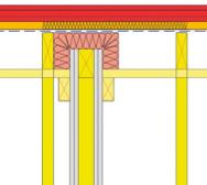
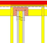
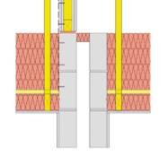
169
11.3
GABLE SPANDREL PANELS
Unlike the party wall or separating spandrel, the Gable spandrel panel is a structural panel to transfer loads from the external gable wind loads into the roof structure which in turn transfers these forces to the building shear walls.
It is not common for the gable panel to provide stability of the roof framing (typically trussed rafters), however, if this is needed the building designer must advise the timber frame engineer or manufacturing company of the requirement.
The gable spandrel panel will provide lateral restraint to masonry cladding for which the gable panel is engineered to take the lateral forces from the ceiling level to verge level.
The connection between the gable spandrel panel to the ladder truss, roof binders and ceiling level junction must be engineered to transfer loads/forces arising from either wind suction or pressure respectively.
Gable panels used in conjunction with timber frame should be engineered for the specific site conditions to allow the gable wind forces to be transferred into the building structure.
To provide stability to the gable spandrel panel and to transfer the imposed loads to other parts of the building, the masonry wall must be connected to the structural gable spandrel panel via wall ties. Wall ties not to be fixed to sheathing boards alone but into the studs and rails.
A single leaf of masonry at a nominal 100mm is acceptable up to 2 stories to the eaves (maximum 6m dpc to eaves and maximum 10m to ridge) under standard construction without the need for sliding wall ties. In addition, up to 9m of height the lateral restraint to the gable spandrel panel can be considered to be provided by standard wall tie connectivity. There is no additional restraint force needed to be resisted. Above these dimensions the building designer is to obtain engineering calculations for the stability of the masonry leaf and restraint forces to be taken by the wall ties, gable spandrel panel and bracing in the roof structure; additional bracing straps may be required for wall panels in excess of 10m from dpc to ridge height.
All wall ties and fixings to be certified for the application and cavity width and checked as suitable for the gable wind forces.
DPC TRAY AT JUNCTION OF MASONRY TO SPANDREL
Gable Spandrel supported on inner leaf masonry wall extended above ceiling level with cavity insulation
170
11.3
MASONRY WALL TIE POSITIONS
171
11.3
11.4 ROOF
COVERINGS
Weathertightness for Roofs¬¬¬
Weathertightness is a key concern with any roof surface. It refers to the resistance of the exterior fabric to natural weather elements such as rain and snow and its ability to prevent moisture from penetrating to the internal environment. Weathertight is not the same as watertight. Submerged under water, almost all buildings would fail. Weathertightness issues can be a significant concern as moisture penetration can cause permanent building damage and can be costly to repair.
The way water ingress manifests are dependent on numerous factors like the location of the building; the rainfall rate for that location; average wind speeds and other factors such as the ability of a system or product to resist the ingress of rain and snow. There are several ways that this may occur, which could include:
• Wind-driven snow.
• Unprecedented rain and snowfall.
• Capillary action and rainwater creep.
• Raindrop bounce and negative pressure rain suction.
• Driving rain, deluge rain and flooding.
Water ingress issues are unique in nature and often represent a combination of contributing factors. However, common causes that stem from installation include:
• Inappropriate specification.
• Incorrect installation of fixings and fasteners.
• Improper usage of sealants.
• Improper detailing of penetrations like abutments, chimneys, and for roofing equipment
• Improper transitions or roof surfaces with insufficient pitch.
• Defective workmanship
• Damage by other trades
The current guidance that covers tiled and pitched roof coverings in the UK is BS 5534: 2014+A2:2018 ‘slating and tiling for pitched roofs and vertical cladding-Code of practice (including shingles)’
This British Standard gives recommendations primarily intended for the design, performance and installation of new build pitched roofs, including vertical cladding, and for normal re-roofing work, including repairs, using slates, tiles, shingles and shakes and their associated components.
The British Standard should be read in conjunction with the following:
• BS 5250:2021 incorporating Corrigendum No 1 Management of moisture in buildings-Code of practice
• BS 9250:2007Code of practice for design of the airtightness of ceilings in pitched roofs
• BS 8612:2018 Dry fixed ridge, hip and verge systems for slating and tiling-Specification
• BS 8000-6:2013 Incorporating Corrigendum No.1 ‘Workmanship on building sites-Part 6 code of practice for slating and tiling of roofs and walls’ This gives recommendations on basic workmanship on building sites, both commercial and domestic, and covers those tasks which are frequently carried out in relation to the slating and tiling of roofs and walls of newly constructed buildings or buildings being refurbished and reroofed. It makes recommendations and gives guidance on basic workmanship for conventional types of building work.
The recommendations given in this British Standard apply to the laying and fixing of clay and concrete tiles, natural slates and fibre cement slates and their associated fittings and accessories. And where needed regulation 7 of the manual to the Building regulations may be used or applicable geographical standards outside of the UK.
172
11.4
Selection and installation for roof coverings
To ensure a roof covering is successful in maintaining a buildings integrity and therefore weathertightness, it is imperative that the materials employed are specified and installed correctly:
Cold Roofing Systems
Cold roof construction is where the insulation is laid between the ceiling joists. This then means that everything above the insulation, such as the rafters, is colder than the living space. Warm, moisture laden air can permeate up through the ceiling. When it reaches the unheated roof space such as the loft compartment the change in temperature creates condensation on the timbers, underlay etc. By ventilating the roof void the free flow of air will moderate the build-up of condensation forming.
Warm Roofing Systems
A warm roofing system is where the insulation is laid on top of the rafters, or in between the rafters and hence everything below the insulation is warm, similar to the living space. (Please note that if a warm roof is being installed it is critical that ventilation is provided within the batten space).
173
Roof System Design Team & Responsibility Confirmed Management of Residual Design Risks Level of RiskHigh, Variable or Low High Medium/Low Design Risk Assessment, including Structural Considerations, Specification & TestedSystems Roof System Design Specification Agreed Design Interfaces with other trades agreed Inspection & Test Plan Agreed No Yes Yes Confirmation that Guarantees are Insurance Backed (IBG) Yes Design Confirmed and Accepted Installation on Site by Approved Installer and QA from the System Provider where applicable Specification including manufacturers’ fixing schedule to be issued to site installers Handover documentation including Contractors and Manufacturers IBG Roof with other & Test are Backed Re-design System
11.4
Thermal Insulation
The design U-values and air permeability limits to be achieved are given in the relevant parts of the Building Regulations of the UK or geographical location outside of the UK based on one of the following:
• The buildings SAP calculation
• Compliance with the National Calculation Methodology (NCM)Simplified Building Envelope Model (SBEM
The insulant utilised to achieve the U-value required may be in several forms or a mixture of several types for example:
• Mineral Wool (either in role form or as a slab)
• Rigid polyisocyanurate (PIR Board)
• Rigid polyisocyanurate (PIR or Phenolic boards)
• Rigid polystyrene (EPS/XPS) slabs.
Thermal insulation must be installed to meet current Building Regulations to an acceptable level of workmanship avoiding cold bridges. At all times the insulation should be installed in accordance with the manufacturers’ recommendations.
To reduce thermal bridges in line with the ‘Fabric First’ approach, junctions within the building fabric and any penetrations through the insulation should be preplanned at design stage and prior to works commencing to ensure robust detaining at these points to minimise any heat loss.
Roof Underlays
In July 2018 the British Standard was revised and BS 5534:2014+A2:2018, came into force. The revision included requirements for a new test to analyse an underlay’s ability to withstand wind uplift.
The UK has five wind zones that indicate the strength of the wind in each given area. Always check with the manufacturer to make sure the underlay can be used in a particular zone. Wind zone suitability applies to underlays where:
• There is a continuous ceiling
• The ridge height is not greater than 15m
• The roof pitch is between 12.5° and 70°
• The site altitude is not greater than 100m
• The site is not more than halfway up a hill or escarpment / cliff with more than 5% gradient
When specifying or using an underlay additional care needs to be taken to ensure that not only is the underlay acceptable for use in accordance with the requirements of the Zonal method but also in accordance with the wind uplift figures stipulated within BS5534 as the wind uplift resistance at the relevant batten gauge needs to equal or exceed the calculated design wind pressure on the underlay for the specific site application.
There are two different categories of underlay in accordance with BS5534:
LR Underlays – Low Water Vapour Resistance (<0.25 MNs/g). These underlays are referred to as ‘vapour permeable’ underlays (VPU) or ‘vapour open’ and provide an extra mechanism of vapour transfer that can be utilised in conjunction with designed ventilation in both cold and warm pitched roofs. They can also be used in non-ventilated cold and warm pitched roofs subject to the air permeability of the roof covering, the ceiling and associated roof /wall junctions being sealed against internal vapour transfer in accordance with the requirements of BS 5250 and BS 9250, or in conjunction with the requirements of a UKAS Accredited Third Party Certificate.
HR Underlays – High Water Vapour Resistance (>0.25 MNs/g). These underlays are often referred to as ‘nonbreather’ underlays that effectively prevent the transfer of water vapour and include many modern membranes and also the traditional bituminous felt (formally known as IF felt). They will always require ventilation of the loft space in the case of cold roofs or between the insulation and the underlay in the case of warm pitched roofs to prevent the risk of damaging condensation.
Note: When installing fibre cement slates LR underlay should only be used if a counter batten is installed giving a free air gap of 50mm between the top of the underlay and the underside of the slate.
To prevent site issues where lightweight underlays have not been installed correctly, in particular the degree of drape when laid unsupported over and between rafters. The following guidance should be followed to avoid such issues:
174
11.4
• Underlays may be laid draped over rafters or counterbattens at recommended spacings suited to their tensile strength. The drape should be sufficient to allow drainage of water away from the batten fixing holes directly above the rafters or supports and beneath the battens (e.g. via a water test if necessary). At its slackest, the drape should be no more than 15mm in order to conform to BS 5534 and BS 8000-6; and minimise the risk of ballooning and contact with the underside of the roof covering.
• Over-exposure to UV light could lead to premature failure of underlays and as such should not be left exposed for any long period of time, and in conditions of heavy rainfall combined with severe freeze/thaw conditions, for more than a few days, prior to the laying of the roof covering. If this is impracticable, temporary protection in the form of a tarpaulin or similar protective sheeting should be used until the roof covering can be installed.
All underlay laps must be secured in some way by a batten or proprietary means whether the roof underlay is fully supported or unsupported. Where the laps are to be secured by battens, there are two methods of complying with the requirements of BS 5534 and BS 8000-6.
The first is to increase the horizontal laps where necessary, to ensure they coincide with a regular batten course. Using this method, more underlay may be used, but no additional battens are required, and trip hazards are avoided.
The second is to maintain consistent underlay laps and, if necessary, to install additional battens over them. It should be noted that if additional battens are used, they should be of the same size and quality as those used for the roof covering.
Laps can also be secured using tapes provided by the manufacturer, or with glue strips integrated into the edge of the underlay.
Where a roof has counterbattens fixed below the underlay, it is important to ensure that the drape of the underlay does not reduce the minimum air gaps required by BS 5250.
NFRC’s website contains a mobile-friendly and easyto-use wind uplift calculator (https://www.nfrc.co.uk/
nfrc-members/technical). It is accredited by BRE for accuracy and provides the wind uplift resistance figure required by BS 5534 to ensure that the underlay specified is fit-for-purpose. It means that contractors can select the underlay with the confidence that the underlay will perform all its functions as designed, throughout the life of the system.
For areas outside of the UK then consult the applicable geographical requirements and associated codes.
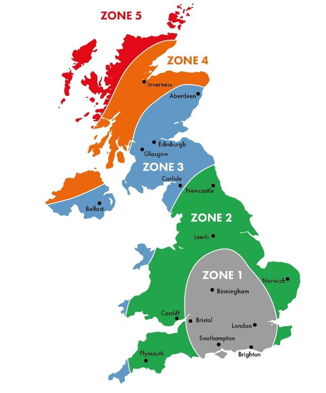
The roof underlay to a pitched roof should be fixed in accordance with the underlay or tile manufacturer’s recommendations, with care taken to ensure that water will run off into the gutter, e.g. by use of a tilting fillet where required.
Roofing felt should be fixed with non-corrodible clout nails or in accordance with manufacturer’s recommendations. Horizontal laps should be not less than 150mm for roof pitches below 35°, and 100mm for pitches greater than 35°. Vertical laps should not be less than 100mm and occur only over rafters, to which they should be securely fixed. The underlay should extend into the gutter and the bottom row of tiles should overhang to the centre of the gutter.
175
11.4
Fixing
Due to the continued changes in weather patterns for the UK and Europe has resulted in changes in the way wind loads are calculate. This in turn has changed and increased the mechanical fixing requirements of slates, roof tiles, ridge and hip tiles and roof systems.
For example:
• All single lapped tiles on a roof now need to be mechanically fixed
• Tiles at the perimeter must now have a minimum of two fixings.
Roof tiles and roof coverings should be fixed in accordance with the manufacturer’s instructions, and their fixing specification for the project/plot with due account being taken of the site exposure. Non-ferrous or stainless-steel fixing nails should be used. Tile clipping should be used as recommended by the manufacturer. Hook fixing of slates is recommended to prevent slipping.
All fixings must meet the requirements found in BS5534 and BS EN 1991-14:2005+A1 ‘Euro -Code 1.
Non-corrosive nails should be used for fixing slates and tiles e.g. stainless steel, aluminium, copper or bronze. Nb. galvanised nails do not have sufficient durability. It is common practice to fix roofing battens with ordinarywire nails. However, in coastal areas or other regions having an aggressive atmosphere, corrosion resistant nails should be used (e.g. galvanised wire nails).
Experience shows that tiles are often not fixed on site as they should be. Builders and designers should determine the required tile fixing specifications necessary for their area e.g. by contacting the tile or roof covering manufacturer who often provides an advisory service. Fixings may consist of either nailing, clipping or both and proprietary dry verge and ridge fixing systems.
The use of mortar to bed roofing tiles is no longer accepted by ICW for warranty purposes. Each ridge and hip tile must be mechanically fixed to prevent uplift from wind loading. Dry verge and ridge systems should be fixed in accordance with the manufacturer’s recommendations.
There is now no longer a need to grade battens on site as all battens that conform to BS 5534 will be delivered to site pre-graded, which can be physically checked prior to use as each, and every batten will be stamped with the following information:
a. Supplier Details
b. Size
c. Origin (imported or British grown, and/ or species code)
d. Graded BS 5534
e. Independent third-party accreditation (Please note that this is not a requirement of BS5534 but is industry good practice to ensure compliance)
Roof battens correctly fixed form a structural and load-bearing element of the roof as they support the dead load of the roof coverings and also the imposed loads caused by wind uplift. Battens should be fixed with 3.35 mm diameter nails which are typically 65 mm long. However, it is important to ensure that a fixing calculation is undertaken prior to works commencing as the type and size of the nail used may need to change depending on the wind loading requirements at the location of the project.
Cut ends at verges should be treated with preservative where they are likely to come into contact with bedded mortar or ideally, the batten turned to ensure a treated non-cut end is exposed to bedded mortar.
For roofs with truss rafters where the batten gauge is more than 200 mm, there should be no more than one batten joint on the same support in any four consecutive courses. Where the batten gauge is less than 200 mm, do not have more than three batten joints together on the same support in any twelve consecutive courses.
Where possible, no section of batten should be less than 1.2 m in length and be fixed in at least three points to the rafters. In some areas, battens will need to be smaller than 1.2 m, and there may be only two fixing points (such as at the top of hips, the bottom of valleys, between dormers). Where this situation occurs, it is advisable to double-check the section of batten to ensure it is knot-free mid-span, securely fixed, and there is no splitting to the ends when nailing.
176
11.4
Recommended Batten Size from BS:5534
Non-compliant battens should not be installed. Ungraded battens may prove weak and vulnerable to failure should the roofer inadvertently walk in these areas whilst covering the roof. The HSE only approve BS5534 graded battens as a secure foothold when installing a tiled or slated roof.
Ventilation
Ventilation is required to reduce the risk of interstitial condensation forming on the underside of the impermeable felt membrane and settling on the timber rafters. When designing ventilation for roofs in the UK the guidance found in Approved Document F should be followed as a minimum as well as additional guidance found in clause 12.5 of BS 5250:2021 and BS EN ISO 13788.
Avoid build up of condensation in roof voids
Excessive condensation in roof spaces can cause decay of damp susceptible materials such as timber, plaster, etc and reduce the efficiency of thermal insulation.
• Cold bridges should be avoided at roof/wall junctions by ensuring continuity of thermal insulation.
• All extraction fans should terminate to the outside of the building and not within the roof void. When making termination joints to atmosphere roofing underlays should be cut neatly around the termination point.
• Extraction ducts in cold roof spaces should be insulated.
• Ensure that roof spaces to pitched roofs are vented on two opposite faces by a 10mm continuous ventilation gap (25mm if roof pitch is less than 15 degrees). A proprietary tray should also be provided to ensure that the ventilation is maintained where the roof insulation abuts the eaves.
• Where the ceiling follows the pitched roof line:
- Provide a 25mm continuous ventilation gap along two opposite eaves and provide additional proprietary ridge or tile vents along ridge line to provide additional ventilation of 5000mm2 per metre run.
- Ensure continuity of the ventilation by preventing the insulation blocking the air flow and maintaining a 50mm air gap between the insulation and the felt.
• For mono-pitched or duo-pitched roofs of greater than 360 degree pitches and 10m spans, provide a 25mm continuous ventilation gap along two opposite eaves and provide additional proprietary ridge or tile vents along ridge line to provide additional ventilation of 5000mm2 per metre run.
177
Minimum Size of Batten Application Up to 450mm Span Up to 600mm Span Slates Double Lap Width mm Depth mm Width mm Depth mm Natural: Sized or Random 50 25 50 25 Fibre-Cement or Concrete 38 25 50 25 Clay and Concrete Tiles Width mm Depth mm Width mm Depth mm Double Lap 38 25 38 25 Single Lap 38 25 50 25
11.4
• For warm pitched roofs even with the use of vapour impermeable insulant it is necessary to provide means to allow vapour to exit the system. The use of a thirdparty accredited vapour permeable membrane, when used in accordance with the manufacturers’ guidance, negates the need to ventilate above the insulation, which may be difficult in roofs with hips, valleys, roof lights and other roofline interruptions.
• It is good design and building practice to carry out a dew point or interstitial condensation analysis to ensure correct detailing is followed to reduce condensation in roof spaces.
Additional guidance for the use of vapour permeable membranes
Alternatively, condensation in warm and cold pitched roofs may be controlled by the use of a Third Party accredited vapour permeable membrane as the underlay in a non-ventilated system. In addition to improving energy efficiency, breather membrane solutions offer long-lasting protection against several threats to building integrity, including condensation and infiltration by water and air. This approach allows for the escape of water vapour through the membrane and exit freely to atmosphere, via laps in the tiles/slates. This method does not require ventilation at eaves, ridges or mid-slope when used in accordance with the manufacturer’s guidance.
Flat Roofs
The revised edition of BS 6229 describes best current practice in the design, construction, care and maintenance of roofs with a flat or curved surface, at a pitch not greater than 10 degrees to the horizontal, with a continuously supported flexible waterproof covering. The supporting structure is either dense and heavy (such as a concrete slab), or consists of framing members supporting a lightweight deck of metal or of timber-based material.
The British Standard should be read in conjunction with the following:
• BS 5250:2021 incorporating Corrigendum No 1 Management of moisture in buildings-Code of practice
• BS 8000-4:1989 ‘Workmanship on building sitesPart 4 code of practice waterproofing This Part of BS 8000 gives recommendations on basic workmanship on building sites and covers those tasks which are frequently carried out in relation to waterproofing.
Flat roofs should be designed as either as:
• Cold roof system
• Warm roof system
• Inverted roof system
• Uninsulated roof system
178
11.4
179
TYPICAL COLD DECK ROOF
11.4
TYPICAL INVERTED FLAT ROOF
TYPICAL WARM DECK FLAT ROOF
BS6229 recommends that all flat roof surfaces (including gutter beds) should be designed with a fall of 1:40 to ensure finished drainage falls of 1:80 are achieved. This should take account of construction tolerances, permitted deviations and deflection under load, and unless justified by more detailed structural analysis to account for deflections/settlement. Where two falls intersect, a minimum finished fall of 1:80 along the mitre should be recommended.
Certain third party certified waterproofing and insulating systems are approved for use with zero falls but back falls are not acceptable. In order to ensure a finished surface with a zero fall, a design fall of 1:80 should be used.
Flat roofs in general should be provided with installers guarantee which encompasses both material and installation supported by an Insurance Backed Guarantee (IBG). Reference should be made to ICW individual policy requirements.
Cold Roof System
Where a cold roof system is used, a fully waterproof breather membrane should be installed in all cold roof systems on the cold side of the thermal insulation to provide both an external air-leakage barrier and as additional protection to the insulation layer against detrimental environmental factors. The membrane should be air-tight (i.e. air-impermeable) but highly vapour open, e.g. less than 0.25 MNs/g (i.e. vapour permeable) and should be taped and sealed to manufacturer’s instructions.
A continuous air and vapour control layer (AVCL) should be provided on the warm side of the thermal insulation and careful execution is required to ensure it is both continuous and fully sealed. The use of battens to support the ceiling boards provides a void which can contain any service cables and pipes thereby avoiding the need to penetrate and reducing the risk
180
11.4
of damage to the AVCL. The whole of the underside of the deck should be exposed to free movement of air. On small roofs this may be achieved by supporting the deck on firrings not less than 50 mm deep nailed to the joists and the provision of vents at the perimeter of the roof.
This type of roof is not now recommended. This is because of the difficulty of forming and maintaining an effective AVCL below the insulation and of providing sufficient cross ventilation above the insulation (see BS 5250). Where this type of construction cannot be avoided the cross-ventilated width between openings greater than 5 m is not recommended.
The vapour control layer when fitted in conjunction with cold deck systems should be carefully fitted with lapped joints and no perforations. The formation of a service void is recommended to avoid perforations.
Glass fibre Reinforced Plastic (GRP) roof systems are acceptable where designed and installed to the manufacturer’s recommendations.
Warm Roof System
A warm roof is installed with the AVCL positioned on the slab/deck on the warm side of the insulation, where it can control the air and moisture movement from within the building. If the AVCL is fully bonded to the slab/deck and sealed to all perimeters and penetrations, this can reduce the wind load on the waterproof covering if the slab/ decking is air permeable.
The insulation must be structurally suitable for any intended loading of the roof, and tightly butted when installed to prevent thermal bridging. An interlocking rebated joint insulation scheme is the most secure way of achieving this. If the insulation is to be mechanically fastened, using thermally broken tubular washers this will help prevent thermal bridging.
Inverted Roof System
An inverted roof has the insulation placed above the waterproofing layer. This type of flat roof is widely used for roofs that are subjected to heavy traffic such as roof gardens, patios and car parks. The insulation should have a high resistance to water absorption and be strong enough
to be able to support the loads that will be imposed on it. Insulation used in inverted roofs should always have rebated or interlocking joints to minimise the risk of thermal bridging.
To regulate the movement of water and to protect against dirt and grit penetrating the joints of the insulation boards, a water flow reducing layer (WFRL) should be placed on top of the installation. The WFRL can be easily damaged or displaced during the installation, so it is essential to take great care on site to ensure the long-term effectiveness of the WFRL.
Because of the difficulty ensuring the long-term effectiveness and integrity of the WRFL on site where it can get damaged, the thermal insulation in inverted roofs is regularly saturated. Therefore, the roof system might remain permanently damp and not achieve the expected thermal performance unless an allowance is made to the insulation thickness.
Flat roof construction should comply with the following:
• All roof timbers (with the exception of inverted warm deck roof timbers) to be preservative treated with all site cut ends treated
• Weatherproof covering to be hot bonded and consist of 3 layers of high performance felt holding appropriate independent third party certificates acceptable to ICW.
• Single layer weatherproofing systems are acceptable with current independent third party certificates acceptable to ICW.
• Chipboard should not be used as a decking material (exterior quality WBP plywood is recommended).
• Flat roofing systems should not be laid during wet weather or when the roof deck has not fully dried out.
181
11.4
182
183
TIMBER FRAME
12.0
12.0 INTRODUCTION
Timber frame is a common term for building structures constructed using timber wall panels comprising woodbased studs, rails and sheathing materials that in turn support joisted floors and roof framing. Timber frame is not the same as mass timber or structural insulated timber structures. Timber frame is most commonly constructed in what is called platform frame techniques. The platform frame method of building timber frame structures is suited to both low-rise and medium-rise buildings. The term ‘platform frame’ derives from the method of construction where floor structures bear onto loadbearing wall panels, thereby creating a ‘platform’ for construction of the next level of wall panels, as indicated in Figure 1.
STRUCTURAL CONCEPT OF PLATFORM TIMBER FRAME CONSTRUCTION
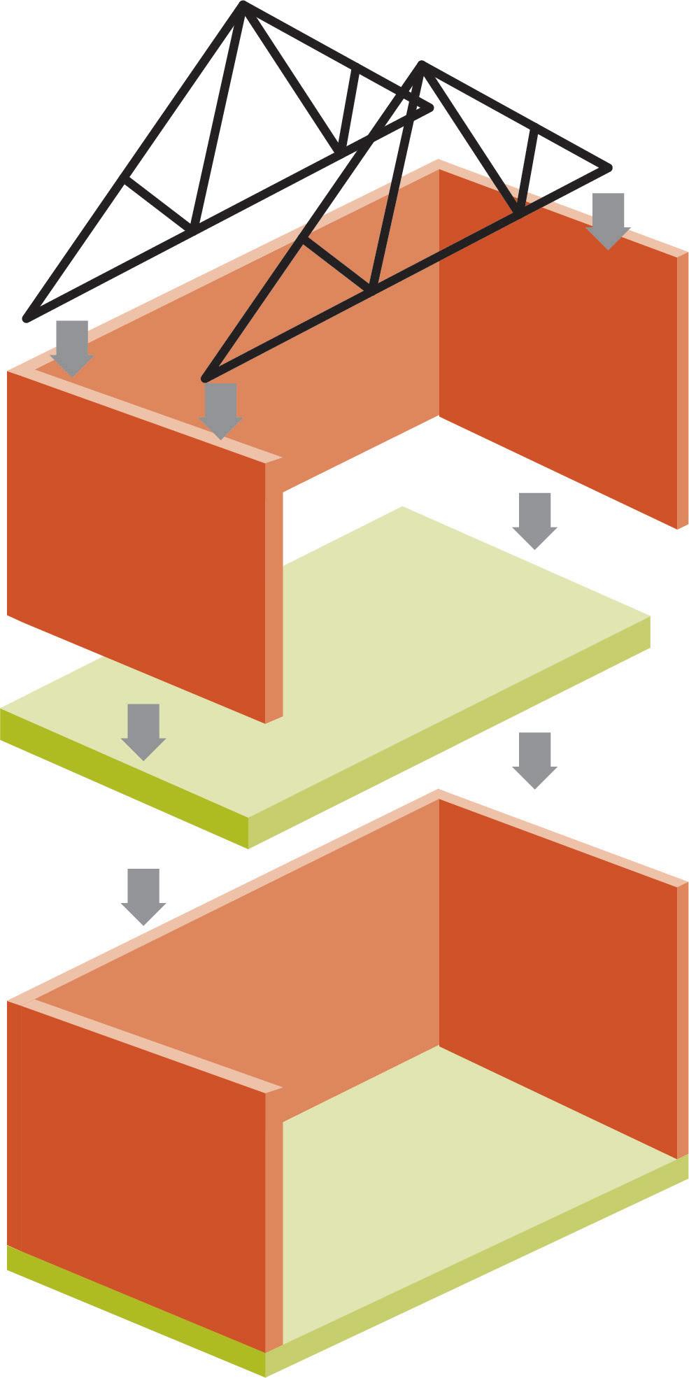
184
FIGURE 1
12.0
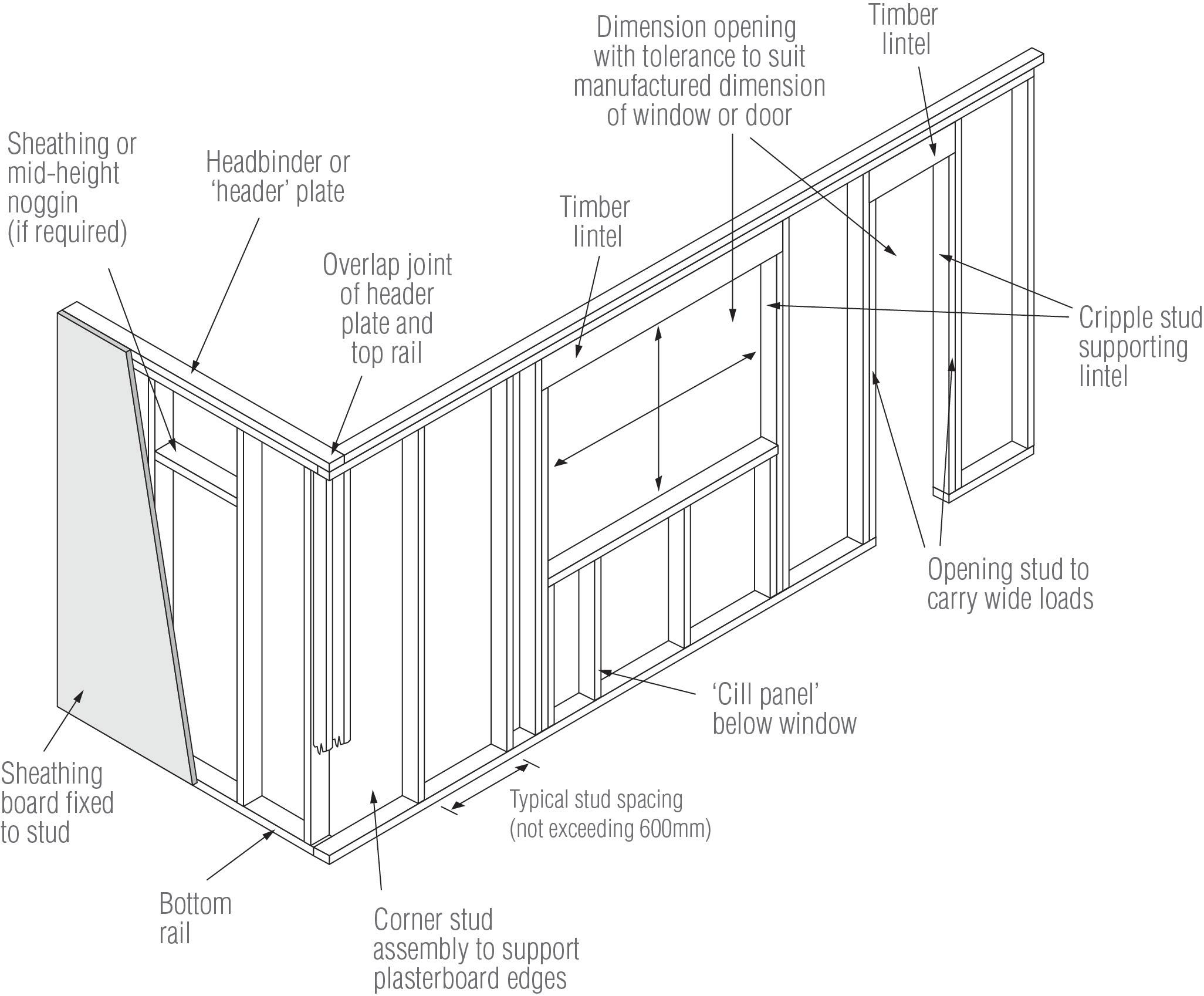
185
12.0
TYPICAL TIMBER FRAME WALL PANELS SHOWING COMPONENT NOTATION
TABLE 1: TYPICAL PLATFORM FRAME MATERIALS
Slates Double Lap
38x89, 114, 140, 184 Canadian lumber size
47 (T1) 97,145,195 (T2) (BS EN 3362)
C16, C24 (BS EN 3381)
Sheathing Boards
9mm, 11mm OSB
9mm plywood
OSB3, OSB4 (BS EN 3003)
Plywood (BS EN 6364)
9mm Magnesium Oxide (MgO) boards Non-combustible board to BS EN ISO 11825
Euroclass A1 and tested to BS EN 5946 and STA product paper 37
15mm OSB
Structural subdeck
OSB3, OSB4 (BS EN 300)
18mm Plywood Plywood (BS EN 636)
22mm Particleboard P5 particleboard (BS EN 3128)
The timber frame assembly is mostly factory built as panels for fast assembly on site. Wall panels can be small or large panel format. The wall panels can include factory fitted insulation between the stud work and an internal boarding may be applied to form what is called a closed panel. Coordinating the interface between onsite elements such as the ground floor slabs and factory produced elements is crucial to the successful delivery of projects. This is particularly relevant in managing the various tolerances expected on on-site elements, that need to be matched to the precision of manufactured off-site components.
The difference in a masonry house and a timber frame is typically the walls. The floor joists and roof frame is similar for timber frame as it is for masonry. Loads are carried by the walls by engineering the capacity of the stud walling. The support of the roof and floors is similar to masonry in that internal load bearing walls may be
present to subdivide the horizontal floor structural spans. Stiffness in a timber frame building to resist wind forces are provided by sheathing fastened to the stud work and the frames are secured to the foundations in accordance with the specific design solution. The finished wall assembly for a house comprises insulation between the studs, a vapour control layer membrane and a dry lining material such as plasterboard over the studs either with a service batten to allow services to be installed before the drylining or direct fix to the studs where services are fitted between the stud work. The external walls have a breather membrane over the sheathing which faces the cavity over which the building façade is completed by either self-supporting masonry laterally tied to the frame or a cladding system attached and supported of the frame.
The timber frame wall can be considered to be a breathable wall where the vapour control layer limits
186
Elements Common
Common Materials
Sizes
12.0
the passage of water vapour from the occupants of the house and the breather membrane allows the internal water vapour to pass through it more quickly than it enters through the vapour control layer; there by the vapour control layer is more resistant to water vapour than the breather membrane. The breather membrane provides a secondary function to stop construction moisture falling on the timber frame and provides a second line of defence against breaching of the façade by rain water.
Cavities to external walls are vented to allow moisture to dissipate.
Prefabricated floors or roof joisted panels are called cassettes and are factory made to suit the design and support conditions specific to the project.
The roofs can be truss rafters as in masonry construction.
TIMBER FRAME PANELS
Fire resistance in timber frame is based on prescriptive approach of initially protecting the timber with a fire rated dry lining such as plasterboard. It is the complete wall assembly, or through the wall assembly, that provides the fire resistance as the insulation, sheathing and stress on the stud in combination with the drylining that provides the fire resistance. Timber Frame is not exposed timber structures although there designs that can be detailed with exposed beams and columns but this is typically in self build bespoke homes.
There are variations in stud types and stud sizes but most commonly studs are graded softwood timber using sizes of 38mm or 45 mm wide and 140mm or 145 mm deep.
STRUCTURAL INSULATED PANELS
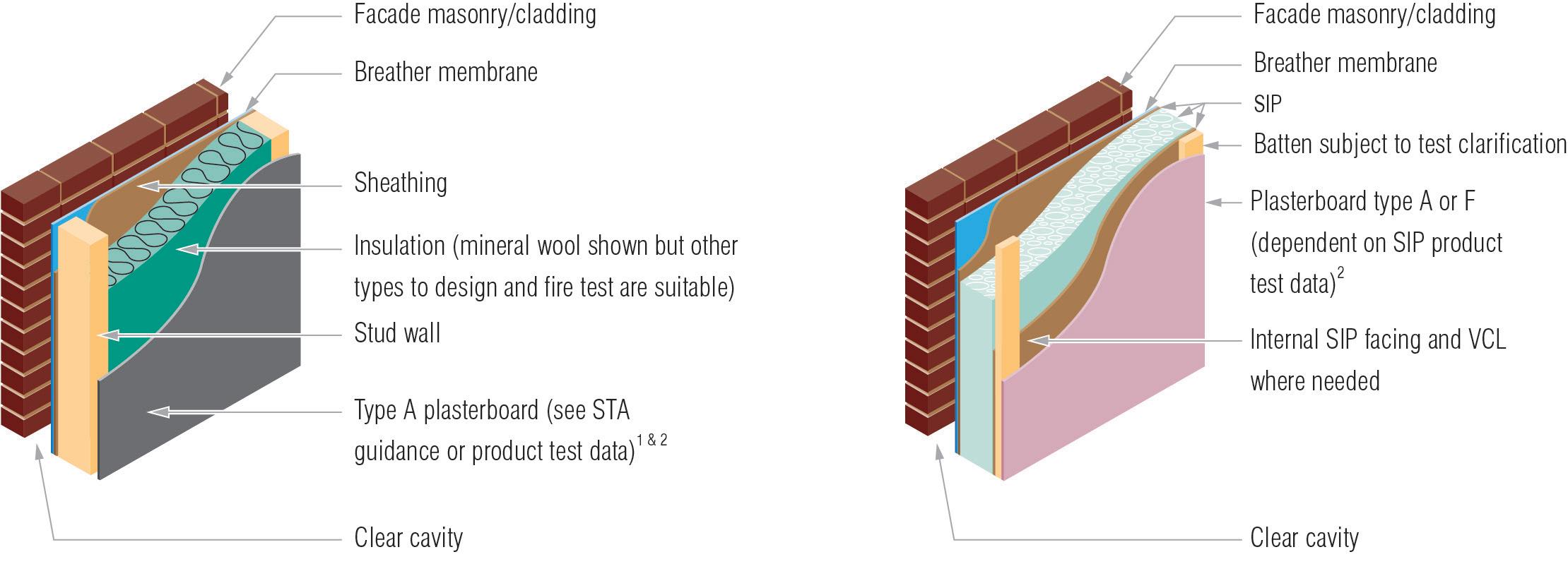
187
12.0
Structural Insulated Panels (SIPS)
Sometimes incorrectly referred to as timber frame, SIPS external walls do not have regular stud centers but are a stress skin factory made product that combines two structural wood based outer boards that sandwich a rigid insulation material creating a stiff composite panel.
SIPs are manufactured off-site under factory-controlled conditions. This panelised form of construction allows SIPs to be assembled to form airtight, building envelopes. The principle is to have as minimal about of studs in the wall to reduce the thermal bridging. Sip buildings adopt timber frame wall techniques for internal walls. There are a number of timber studs necessary at window and door openings.
SIPs panels can be used in walls and panel roofs. Floors are the same as timber frame and alternative roofs such as trussed rafters can be used. As these are manufactured off-site building components the coordination with foundations is critical.
Structural Insulated Panels (SIPS)
With every timber framed system, the structure should be able to withstand wind, snow, imposed due to usage and dead loads and transmit these safely to the ground. All timber frame structures shall be designed in accordance with BS EN 1995 (Eurocode 5).
The whole timber frame system should be structurally designed by a suitably qualified person experienced in timber frame construction.
EXAMPLES OF BUILDING LAYOUTS AND THEIR INFLUENCE ON OVERALL STABILITY
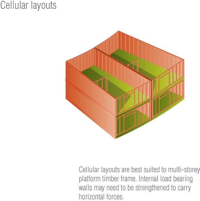
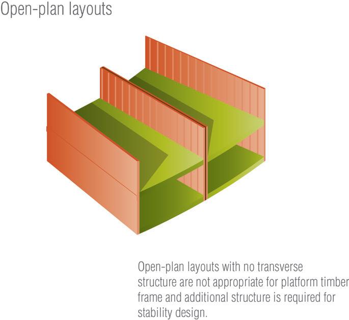
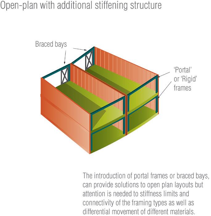
188
12.0
EXAMPLES OF BUILDING LAYOUTS AND THEIR INFLUENCE ON OVERALL STABILITY
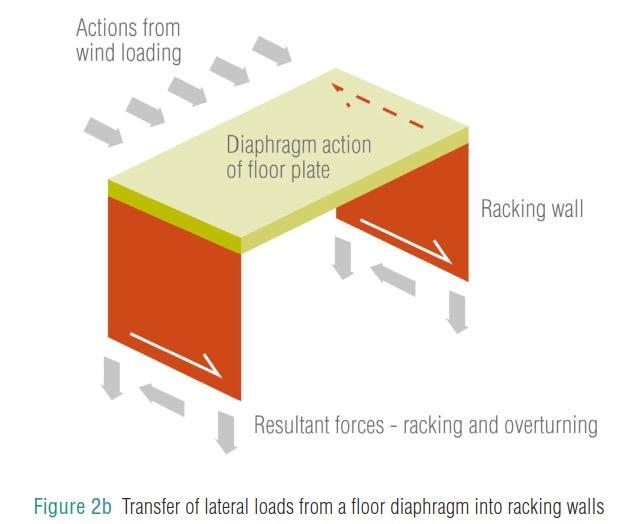
DETAILS OF EFFECTIVE ANCHORAGE OF FLOORS TO TIMBER FRAME WALLS
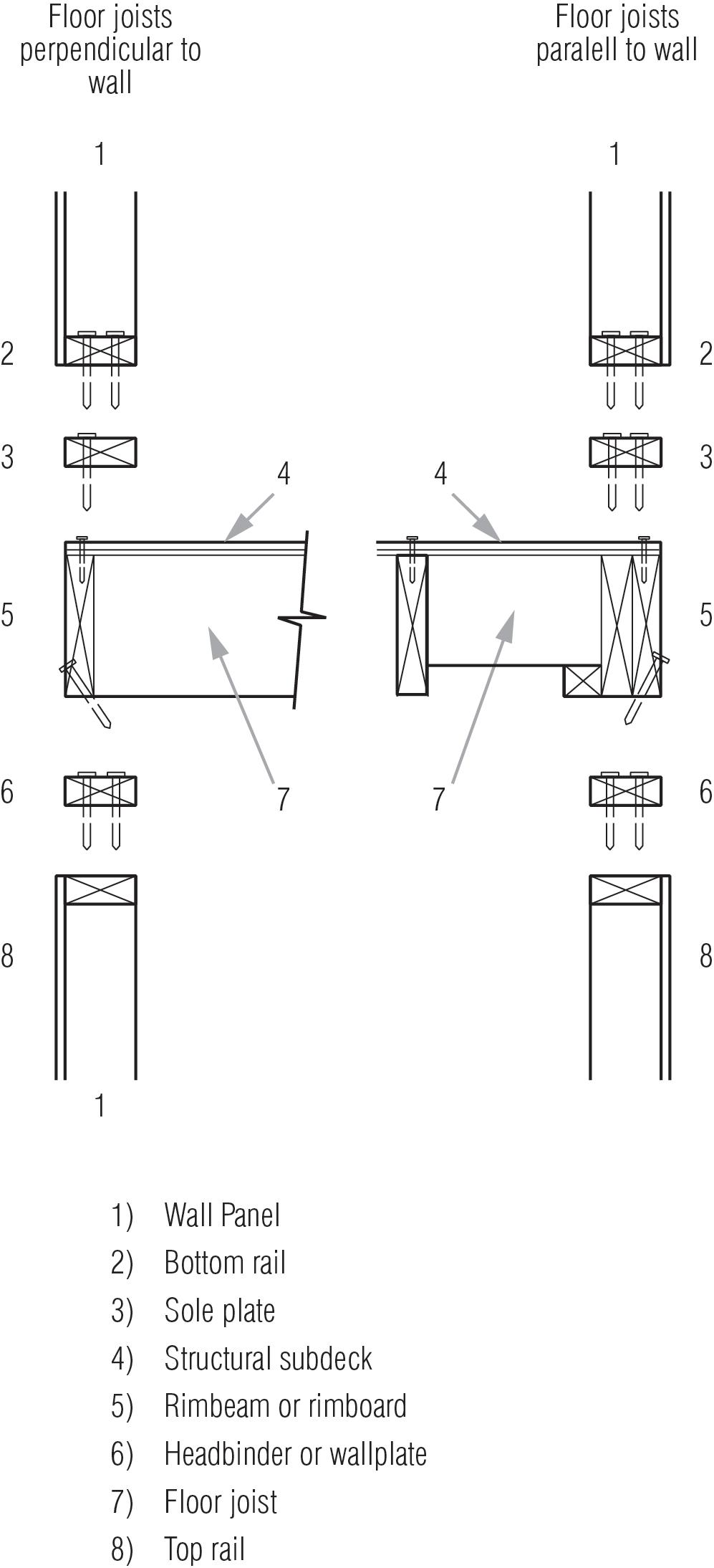
189
12.0
To achieve its stability, platform timber frame construction relies on the diaphragm action of floor structures to transfer horizontal forces to a distributed arrangement of loadbearing walls. The load bearing walls provide both vertical support and horizontal racking and shear resistance.
Due to the presence of open-plan or asymmetric layouts or the occurrence of large openings in loadbearing walls, it may be necessary to provide other means of providing stability to the building, for example by the use of ‘portalised’ or ‘rigid’ frames or discrete braced bays.
Ensure the system is:
• Designed by a suitably qualified person(s).
• Supplied with clear precise instructions for erection.
• Supported with structural calculations. Available for inspection by ICW.
There are a number of different conditions that need to be satisfied by the structural engineer during the engineering of a multi-storey timber frame building, including:
• The adequacy of vertical load paths
• The strength and stiff ness of the individual framing members
• Overall building stability and stability of the individual elements
• Robustness of the framing and connections
• Disproportionate collapse design for which houses are class 1 and low rise up to 11m upper floor level class 2A
Sip panels requiring notching and other perforations through the panel should be designed by a suitably qualified person and approved by the systems supplier.
All timber elements should be fixed with correctly designed, durable fixings and restrained in a manner capable of resisting excessive movement caused by drying shrinkage or applied loads.
Once timber frames have been erected, it is essential that the cladding and roof covering is installed as soon as possible to provide protection to the external fabric of the building. In no circumstances should the timber frame be left exposed for a period greater than specified by the manufacturers of either the frame or the breather membrane.
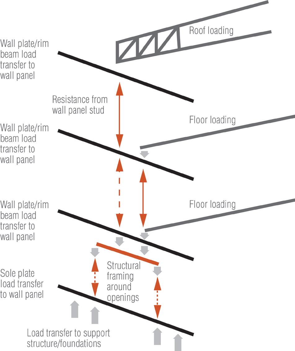
190
12.0
Quality Assurance
Timber Frame manufacturers and installers should possess correct and current certification from one of the ICW approved quality assurance schemes, such as:
• Structural Timber Association’s “STA Assure”. The STA have quality standards for designers, bronze, silver and gold where the increased recognised skill levels and auditing of the company is recognised the higher the level. The STA Assure process requires an certificate from the STA designer which is covered in STA Technical note 19.
• BM Trada’s “Q Mark”
• ISO 9001 audited quality assurance programme for company procedures.
• CE or UKCA Marking for components where relevant. It is understood however that CE or UKCA marking is not available for whole building systems. Timber frame building kits can be manufactured according to a European Approval Document and the relevant European Technical Approval obtained by working with a notified body. CE or UKCA marking is available for most components, either through a harmonised standard or a European Technical Approval.
Materials
All materials used shall:
• Be adequately protected and stored correctly. Avoid water ingress into timber frame panels by keeping them away from standing water.
• Comply with relevant British Standards or equivalent European Technical Specifications, with the certification and documentation available for inspection by ICW.
• Be installed as per Manufacturers details.
• The design will highlight what components shall be preservative treated. Commonly external wall panels and all sole plates are preservative treated in accordance with BS EN 335
Structural Timber:
• All structural timber shall be graded in accordance with BS EN 14081 .
• All load-bearing solid timber studs, rails, binders and sole plates should be regularised, bear a stress graded stamp of a minimum dry graded C16, although the use of C24, being of higher grade, is readily available.
• The moisture content of structural timber should not exceed 20% at the time of stress grading and at the time of erection.
• All structural timber for use within the building fabric should be stress graded and marked ‘KD’ (Kiln Dry) or ‘DRY’.
• Use of Oak:
• Green, air dried or seasoned oak is not acceptable by ICW for warranty proposes for use in external or internal walls or roof constructions.
• Certified Kiln dried Oak with a moisture content of 12% or less may be acceptable for parts of the structure where the Oak is not part of the waterproof envelop.
• All structural sheathing products used shall comply with BS EN 13986 .
• All plasterboards used shall comply with BS EN 520.
Panel Products:
• All structural sheathing products used shall comply with BS EN 13986 .
• All plasterboards used shall comply with BS EN 520
Engineered Timber Products:
• Any structural Glued Laminated (Glulam) products used shall comply with BS EN 14080 .
• Any trussed rafters shall be fabricated to comply with BS EN 14250 .
• Any Laminated Veneer Lumber (LVL) products shall comply with BS EN 14279 and BS EN 14374 .
191
12.0
Workmanship
All off-site fabrications shall be carried out by competent practitioners. STA Assure provides guidance on quality systems; and BBA, BM Trada OR Kiwa building systems may also be seen as a quality mark.
During the on-site construction phase:
• Timber frame systems shall be erected by competent installers.
• All workmanship shall be completed to a standard that fulfils the design and meets the relevant standards or best practice guidelines.
• Timber frame system shall be protected against unnecessary damage, particularly due to water ingress and mechanical damage.
Check Edges
The edge must be within +/- 10mm of the straight measurement line
• All design and Installation specifications shall be followed.
• All products and materials shall be inspected for suitability for their purpose.
Substructure
It is essential that the accuracy of setting out of the foundations is checked well in advance of delivery of materials to site. Any design changes noticed/required at this stage shall be approved by the manufacture/ designer of the timber frame.
The substructure should be checked for dimensional accuracy against the requirements of the timber frame design. However, in general term the following sketches.
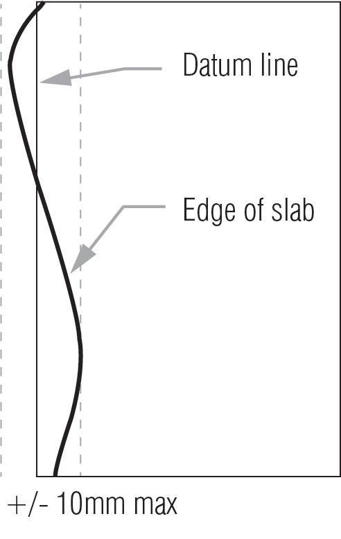
192
12.0
Check substructure level
Concrete slabs must not be more than +/- 5mm from datum. Over the whole slab, the level must not be out by more than 10mm.
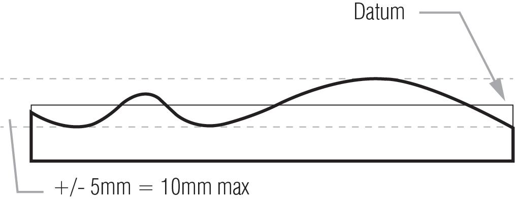
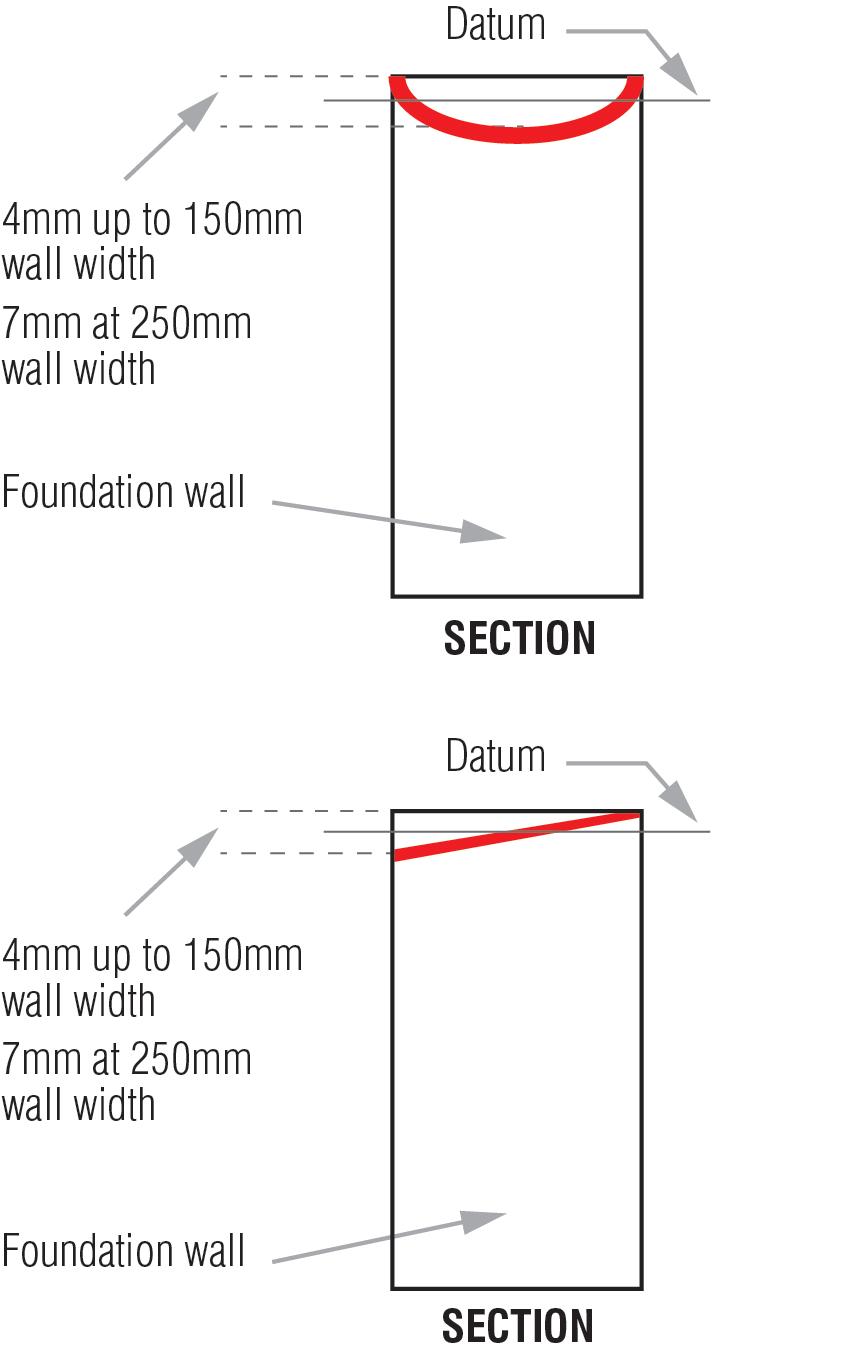
193
12.0
Check level of foundation walls
12.1 SOLE PLATES
Sole plates
Ensure sole plates are properly located and fixed to the substructure.
The sole plates or the lowermost timber plate should be set level, accurately set out, and fixed as specified in the design.
• Deviation in level should not be greater than 10 mm per 5m run.
• Sole plates should not overhang the substructure by more than 10 mm, nor be set back from the edge of the substructure forming a ledge where mortar and debris could collect. Should a ledge be unavoidable then install a damp-proof tray.
Packings where necessary should:
• Not exceed 20 mm.
• Be non-compressible.
• Be located below vertical stud positions.
• Be durable and corrosion resistant.
• Be as wide as the timber frame.
ACCURACY OF SETTING OUT
The structural frame engineer is to be consulted if the sole plate extends or is set back by more than 10mm
• Bedding under frames to accommodate variations in level should be made with a durable noncompressible material of full frame width. The maximum depth of the bedding should not exceed 20mm.
Sole plates with a Damp Proof Course (DPC) underneath should be shot fired or mechanically fixed as per manufacturer’s design to the substructure masonry. It is preferable to use straps or shoes, but where specified care should be taken with shot fixings as to not damage the supporting masonry or split timber members.
Holding down anchors, straps or shoes to be of either stainless steel, phosphor bronze, silicon bronze or galvanized mild steel (940 g/m2) at suitable centres.
Mechanical fixing points are to be as specified in the design. Typically, these are provided at each side of every opening, at corners and at a maximum 2.4m centres. All in accordance with manufacturers’ fixing schedule.
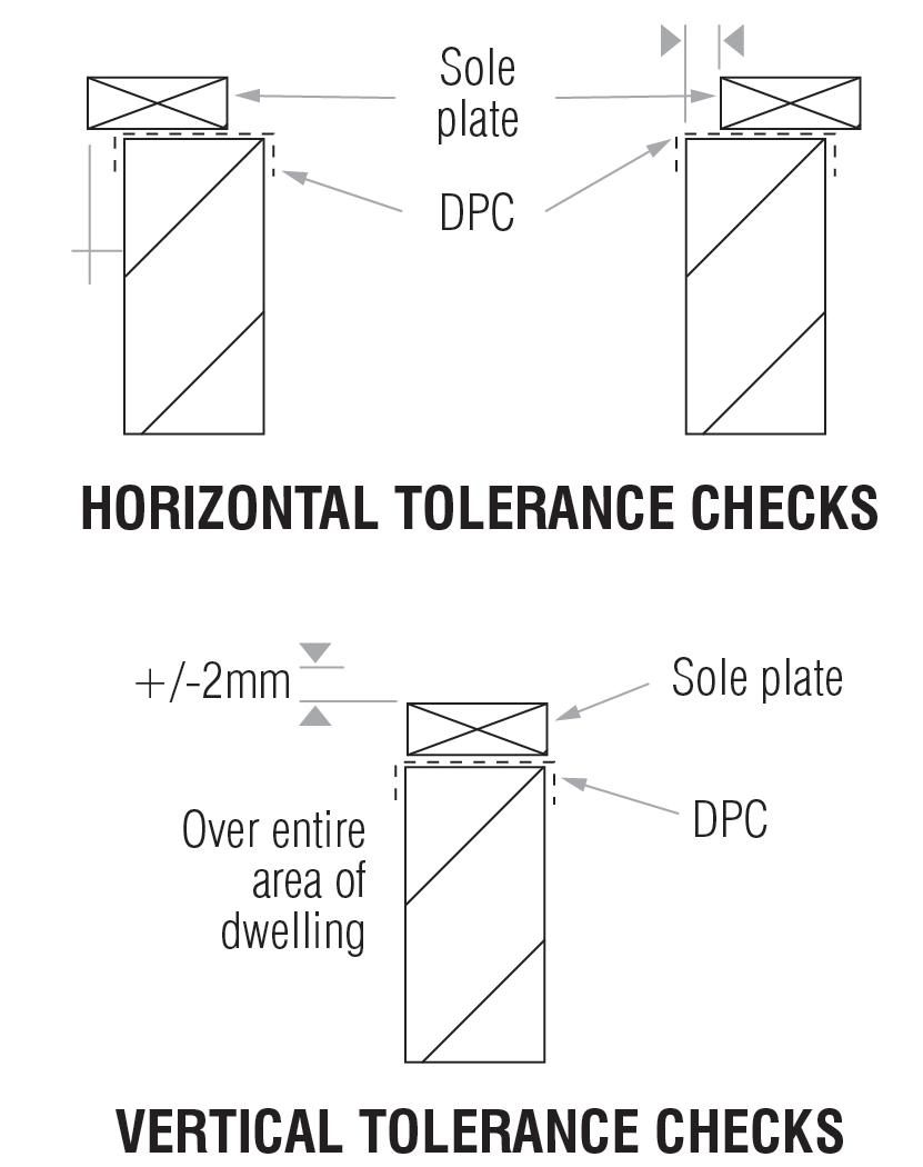
194
12.1
PERMANENT STRUCTURAL PACKING UNDER SOLE PLATE
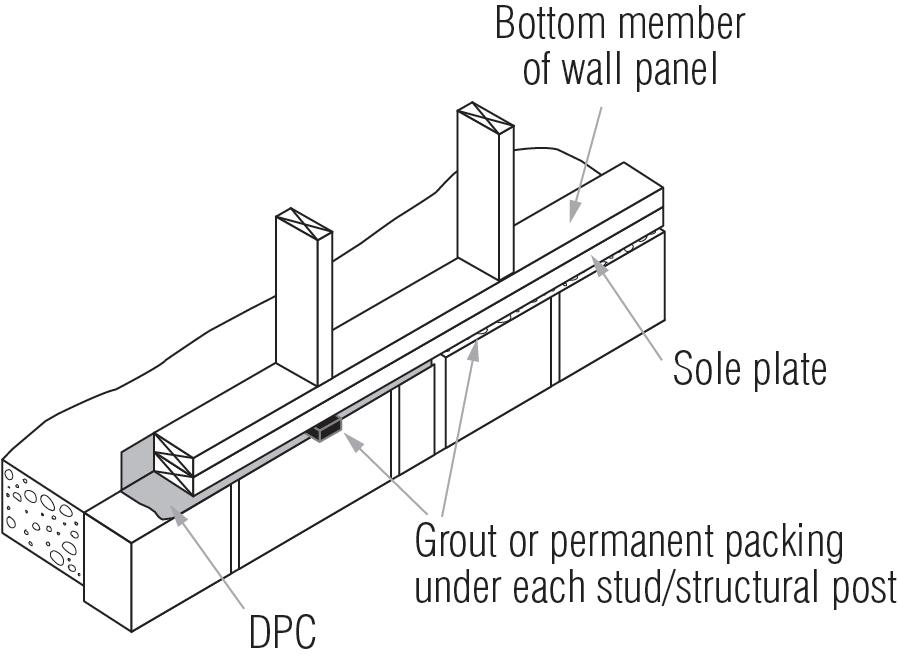
The Sole plate is levelled on temporary spacers (no greater than 0.9m centres). After the ground floor wall panels and floor over or roof structure have been erected, then permanent packing is placed under the sole plates. This packing can be:
• Free flowing non shrinkable grout along the full length and width of the sole plate.
• Individual durable robust packers placed under the full area of each load point.
195
12.1
BEDDING OF SOLE PLATE
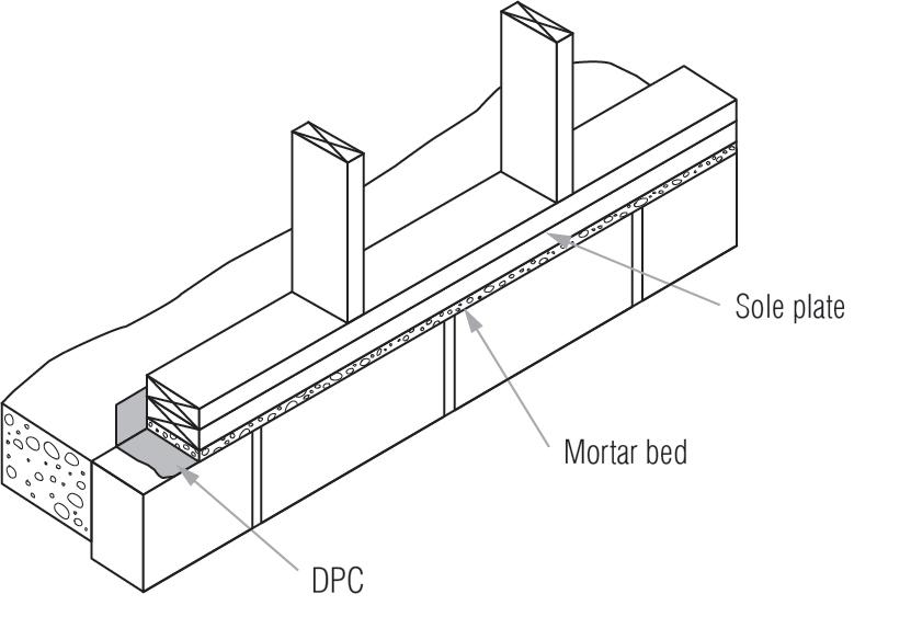
The sole plate is laid on a continuous level bed pr mortar, prior to wall panel erection. The mortar should extend the full length and width of the sole plate.
The sole plate is checked for line and level and spacers may be used to do this.
196
12.1
DOUBLE SOLE PLATE ‘SANDWICH’
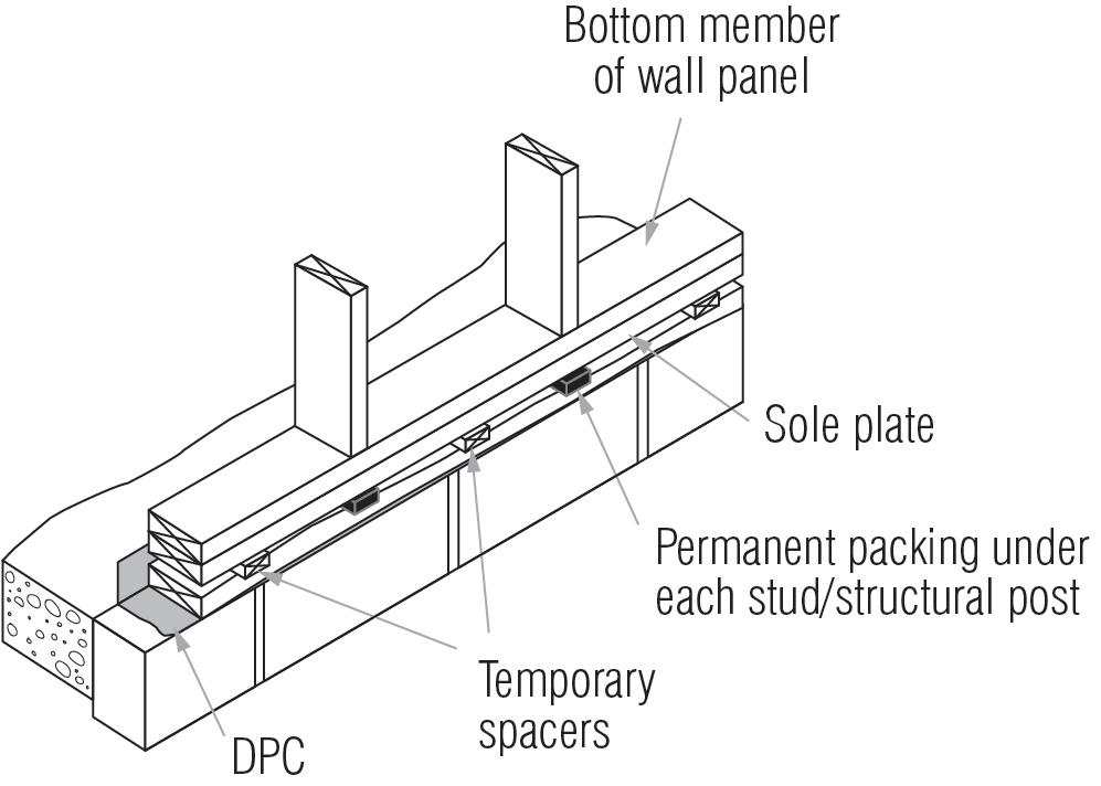
The lower sole plate is fixed along the contours of the supporting structure. The upper sole plate is fixed on top and levelled with temporary spacers inserted between the sole plates.
Once the first lift construction has been erected, permanent timber or robust packing is inserted under each load point for the full area.
197
12.1
Sole plates should not be fixed to infill blocks of proprietary masonry flooring systems i.e. block and beam floors. In such cases suitable anchoring straps must be fixed to the substructure masonry to provide adequate fixings. These are typically ‘L’-shaped with the top part nailed to the timber frame and the bottom built into the outer leaf of masonry.
With masonry, special density ‘nailable’ blockwork is required. With concrete the fixings should not be closer than 75mm from the edge of the slab.
Protect sole plates from damp:
• Sole plates must be preservative treated and laid on a DPC which is lapped onto the slab DPM.
• Wall panels should be skew-nailed to sole plates without perforating the dpc.
• Breather membrane should extend over the sole plate.
• It is recommended that the inner leaf dpc is turned up approximately 30mm above screed to protect sole plate and bottom rails from construction moisture and spillage.
• Cavity fill concrete should terminate no closer than 150mm (225mm recommended) below the dpc.
• Drain and ventilate cavities below dpc level at 1.35m centres. e.g. open perpend mortar joints. Centres may vary dependant on geographical requirements. For example, in Scotland these should be provided at 1.2m centres.
NOTE: the use of holding down straps is not common and can cause more problems than solve.
198
TIMBER FRAME, TYPICAL GROUND FLOOR DETAIL
12.1
Timber Frame Stud Walls
Where elements were originally designed as stressed skin panels, any notching, drilling and other perforations through the stressed skin comprising of sheathing as well as studs forming the stressed skin panel, should be designed by a suitably qualified person and approved by the systems supplier.
All timber elements should be fixed with correctly designed, durable fixings and restrained in a manner capable of resisting excessive movement caused by drying shrinkage or applied loads.
DIAGRAM: HOLES IN STUDS OR POSTS
Framed walls should be accurately aligned, plumbed levelled without twist and securely fixed to adjacent elements using durable fixings suited to the location of the element.
Unless designed by an suitably qualified person, holes for electrical services may only be drilled on the centre line of timber studs between 0.25 and 0.40 of height.
Maximum hole size is 0.25 of stud depth. Timber studs should not be notched.
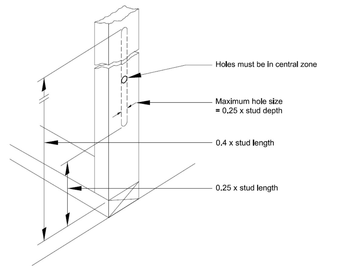
199
12.1
12.2 FIXING
Avoid the following defects:
• Gaps between panels.
• nails missing at panel-to-panel connection.
• Bottom rails not securely fixed to sole plates.
• Plates, rails and studs cut away for services and holes drilled for electrical services near edge of stud.
• Use of damaged wall panels, i.e., splits, cracks within timbers or where vertical studs have been subject to impact there is visible deflection.
• Upper-deck wall panels nailed to floor decking only and not to joists.
• Inadequate packing under upper storey panels.
• Studs out of plumb.
• Studs missing or overloaded.
• Missing head binders.
• Split timbers caused by nailing too close to edge of timber.
• Lack of continuity of vapour control layers and breather membranes at intermediate floors and gables etc.
TIMBER FRAME, FIRST FLOOR DETAIL
200
12.2
Sheathing
Sheathing is usually provided for timber framed walls to provide increased bracing, strength and stiffness to the structure, or simply to protect the building from the elements prior to fixing the external cladding. Sheathing boards must comply with BS EN 13986.
The following boards are acceptable:
• Orientated Strand Board (OSB) and should be grade 3 or 4 in accordance with BS EN 300.
• Plywood should be Class 3 Structural in accordance with BS EN 636.
• Impregnated soft boards should be Type SB.HLS in accordance with BS EN 622-4 .
• Medium board should be type MBH.HLS1 or MBH. HLS2 in accordance with BS EN 622-3 .
• Tempered hardboards should be Type HB. HLA1 or HB.HLA2 in accordance with BS EN 622-2 .
• Other board material with suitable third-party certification acceptable to ICW for primary racking resistance.
Where sheathing provides racking resistance to wind and other lateral loads, the edge distance and spacing of the fixings are critical and should be to the relevant standards or to the best practice guidance from the STA or the Institution of Structural Engineers (IStructE).
When fixed on site, sheathing should be nailed to stud members with galvanised, sherardised, stainless steel, phosphor or silicon bronze nails at centres to the approved design. Nails must not be overdriven.
Sheathings for dwellings that are subject to extreme exposure conditions on sites located in areas defined as ‘very severely exposed’ should be designed using either improved protection of standard durability or alternatively, an enhanced level of sheathing durability. Such dwellings would not be sheltered by local features, including surrounding buildings and trees, and therefore would not qualify for the reductions of exposure category permitted.
Breather Membranes
Breather membranes are normally provided to the face of sheathing as an additional waterproof barrier in cases where rainwater entering the cavity can come in contact with the timber frame construction. Breather membranes are usually pre-fixed in the factory to timber frame wall cassettes.
Where no breather membrane is required as specified by manufacturer (e.g., where bitumen impregnated fibreboard is used) the joints between sheets should be taped.
Impervious roofing felts are not suitable as breather membranes.
If applied on site, breather membranes should be lapped by 100mm horizontal and 150mm vertical and the sole plate by 25mm.
Identification marks on the breather membrane should point the location of the timber studs to help with the cladding trades.
Breather membranes with the following characteristics should be specified by the design:
• A type 1 membrane in accordance with BS EN 13859-2 . (Superseded BS 4016 may also be referenced)
• Non-contributor to fire.
• Securely fixed to protect the outside face of the timber frame structure with austenitic stainlesssteel staples.
• Lapped and where required taped in accordance with Manufacturers’ requirements.
It should be noted that in areas designated as ‘very severe’, only ‘high performance’ breather membranes can be used.
201
12.2
Avoid the following defects:
• Breather membrane torn at service entrance points.
• Laps are too small.
• Breather membrane damaged by site work, wind or over exposure to sunlight (UV degradation).
• Laps in breather membrane in wrong direction allowing ingress of water.
• Breather membrane not extended to protect sole Plate.
• Marker tapes, or identification marks for stud locations are inaccurate or absent.
• Breather membrane not lapped over lintels.
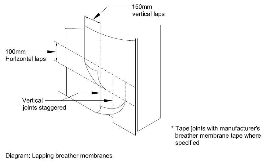
202
12.2
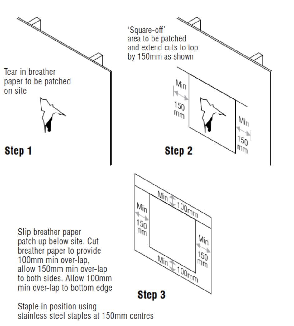
203 12.2
12.3 THERMAL INSULATION
Thermal insulation
The use of insulation materials will be dependent on the buildings SAP calculation, and it is advised that the manufacturer’s details are followed when installing.
Fixing of thermal insulation
Generally:
• Flexible quilts should be mechanically fixed between studs to avoid sagging (eg, by stapling).
• Particular attention is required to avoid cold bridges at internal/external wall junctions where it is difficult to fix insulation between closely spaced studs.
• Wall insulation should extend down to floor insulation (or provide perimeter insulation to slab edge).
• Where rigid insulation is used then a minimum 25mm service void should be created by battening out. This is to avoid service runs being cut into the insulation board.
Avoid the following defects:
• Thermal insulation missing.
• Gaps between thermal insulation and studs.
• Thermal insulation not continuous above lintels and at junctions with other walls.
• Quilt type insulation:
• Paper backing on thermal insulation not stapled to studs.
• Sagging thermal insulation (cold bridges).
• Thermal insulation squashed (reduced efficiency).
Vapour Control Layer (VCL)
The purpose of the Vapor Control Layer or VCL is to mitigate the risk of interstitial condensation and to prevent the passage of moisture through the structure of the wall. There are various VCL available and it is recommended that the installer follows the technical guidance produced by the manufacturer.
Suitable vapour control layers include:
• 500gauge (125μm) sheet polythene (manufactured from virgin polymer) or metalised polyester backed plasterboard (not foil backed plasterboard).
• Sheet polythene is preferred to plasterboard due to the problem of sealing board joints.
• Where metalised polyester backed plasterboard is used as a vapour control layer, it should be fixed in strict accordance with the manufacturer’s instructions, in particular ensuring that joints occur at studs and noggings, and are filled and taped.
Fixing of vapour control layers
Condensation can cause timber decay and reduced efficiency of thermal insulation.
In general terms in the Northern Hemisphere VCLs should be provided to timber frame external walls on the warm side of the principal layer of insulation.
“Warm wall” constructions (thermal insulation located outside sheathing) normally do not require a vapour control layer. Such systems need to be approved by an independent assessment authority and is also dependent on air-leakage test requirements.
Avoid the following defects:
• Vapour control layer with gaps at joints
• Holes in vapour check plasterboard and tears in polythene vapour control layer
204
12.3
TYPICAL CAVITY BARRIERS, VENTILATION AND CAVITY DRAINAGE
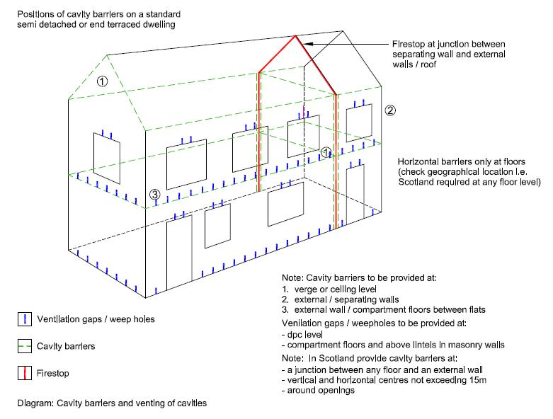
Note that the party wall fire stop is a name provided for the edge sealing of the party wall to provide EI 60 between the two dwellings; this may be formed in a number of ways.
The STA Vol 2 – cavity barriers and fire stopping guidance provides guidance on design , installation and checking of cavity barriers and fire stops.
205
12.3
12.4 VAPOUR CONTROL
It is considered unnecessary to provide weepholes to the base and head of a timber-framed building, provided an equilibrium of moisture and air within the cavity behind the external masonry cladding can be achieved. However, where this is obstructed by, amongst others, horizontal cavity barriers and associated trays then they need to be introduced to maintain ventilation to the timber frame.
Weepholes are therefore only required at the foot of the wall, usually at ground level, therefore eliminating the need to vent the cavity.
The exception to the provision of one set of weepholes is where the cavity is bridged by lintels or stepped dpc etc. in the normal way or where a fire barrier is provided at a floor level at separating floor, in which case weepholes are required directly above the fire break to allow any moisture entering the cavity to be readily drained away.
The use of a vent/weephole ventilator incorporating an insect resistant grille is recommended.
Cavity widths should be:
• Masonry, 50mm this in particular to allow cleaning of walls ties.
• Render, 25mm when the mesh or metal lathing is backed by a breather membrane
• Render, 50mm when the mesh or metal lathing is unbacked
• Other claddings, 19mm
It should be noted that ICW will accept ‘no cavity’ for proprietary render systems. The design will be assessed on individual merit with also the following criteria to be met:
• Accompanied by a third party accreditation of the render system, appropriate for timber frame and acceptable to ICW.
• Accompanied by an Interstitial condensation assessment.
• Breather membrane to not only be lapped but taped in accordance with the breather membrane manufacturer’s tape.
• A suitable EDPM to be installed around all external frames and penetrations through the external timber frame envelop.
• The base of the substructure at ground level to be drained with weep holes at 1.35m centres.
Air Tightness
At all times the technical details, manufacturer’s installation techniques and information designed within the SAP calculation should be adhered to ensure air tightness of the building in accordance with relevant guidelines.
206
12.4
Wall ties
Fixing of wall ties:
• Wall ties should be fixed to studs with stainless steel, phosphor bronze or silicon bronze nails at the correct centres to the design specification.
• Wall ties should be flexible stainless steel or equally durable.
• Ties should be fixed to studs, not sheathing, at centres not greater than 600mm horizontally and 450mm vertically (300mm to reveals and either side of expansion joints)
• Wall ties should be embedded in mortar joints to a minimum depth of 50mm with a slight fall towards the external masonry. Ties should be fitted to the centre line of the studs.
Tie should not have collected mortar droppings.
Avoid the following defects:
• Wall ties nailed to sheathing only, instead of the studs.
• Wall ties not sufficiently embedded in external masonry.
• Prefixed wall ties not coinciding with masonry mortar joints.
• Mortar droppings on cavity wall ties.
• Wall ties sloping backwards to the timber frame.
• Rigid wall ties used instead of flexible ties.
• Do not straighten pre-bent ties.
TYPICAL STAINLESS STEEL TIMBER FRAME WALL TIE
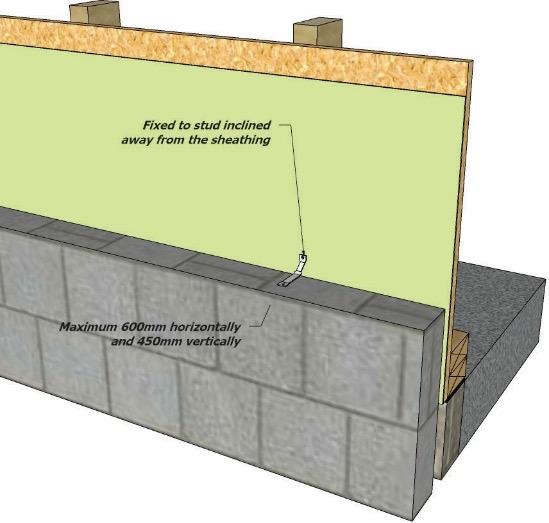
207
12.4
12.5 MOVEMENT CONTROL
Movement Control
Masonry
Ensure that differential movement between timber frame and independently supported claddings such as masonry can take place, particularly at:
• Eaves and verges
• Window and door sills
• Make allowance for vertical sliding of masonry against side of openings by providing a flexible mastic joint between reveals and frames.
• Where cladding horizontally abuts masonry, provide a movement joint to allow for differential movement.
• Where cladding vertically abuts masonry, provide a movement joint with drainage channel discharging onto a cavity tray DPC.
Timber cladding
Where timber cladding spans across a floor zone, provide a movement joint to accommodate timber shrinkage.
Cement render
• Where cement render on lath fixed to the frame spans across an intermediate floor zone in timber frame construction, allow for differential movement due to timber shrinkage by incorporating a weathertight movement joint using a proprietary render stop.
• Vertical movement joints should also be provided at maximum 5m horizontal centres to render panels.
• A movement gap must be maintained below any horizontal render stop bead on masonry below timber frame.
• Note – follow manufacturer’s guidance on movement for proprietary render systems.
Avoid the following defects:
• Ensure the roof is loaded prior to commencement of masonry outer leaf or cladding. This is to avoid inward sloping wall ties once ‘dead’ loads are in place.
• Insufficient allowance for shrinkage of timber frame relative to masonry at eaves, verges, windows and door sills.
• Cracking of cladding due to absence of a movement joint between different types of cladding.
• Absence of movement joint where timber or render cladding bridges intermediate floor zones.
• Failure of weather-tight joint at window jambs due to shear from movement.
208
12.5
TYPICAL MOVEMENT CONTROL
209 12.5
12.6
12.6 CLADDING
Timber
The timber framed structure should be fitted with an appropriate cladding system which may take the form of brickwork, rendered blockwork or lightweight rain screen system. Whichever system is used adequate provision for drainage and ventilation should be provided according to the design drawings.
Where proprietary systems are used, third-party accreditation acceptable to ICW is to be provided. Manufacturer’s guidance is to be followed.
Masonry cladding should be planned to accommodate clearance between window sills, soffits, balcony structures etc., for differential movement. The gaps should be filled with a compressible filler.
Preload the timber frame within structural limits with roof tiles and internal sheeting prior to the installation of masonry cladding.
Claddings fixed directly to frame:
• Boarding to be preservative treated, minimum 16mm thick and sufficient tongues or overlaps provided to permit shrinkage and expansion of the timber.
• Timber boarding should be battened off the sheathing to provide a minimum 19mm cavity for draining and venting.
• Battens should be a minimum 38mm wide, preservative treated and at maximum 600mm centres.
• Battens should be fixed to each stud (and not to sheathing) with annular ring shank nails of length at least twice the batten thickness plus the sheathing thickness or plain nails of length at least 2.5 times the batten thickness plus the sheathing thickness.
• Counter battens to be used for vertical cladding.
• All nails to be fixed at 600mm centres.
• Timber cladding boards should be fixed to battens by face or secret nailed with annular ring shank nails at least twice the board thickness or plain shank nails at least 2.5 times the board thickness.
• Butt joints at board ends should occur at and be supported by battens.
• Nails should be either hot dipped galvanised, stainless steel or equally durable.
• Galvanised nails should not be used with Western Red Cedar.
• Corners and reveals should be formed to provide a weather-tight construction.
• Plywood sheets used as cladding should be pressure preservative treated, a minimum 12mm thick and bonded with WBP or equal quality exterior adhesive and marked accordingly. Battens should be vertical and treated. Joints between sheets should be made resistant to excessive water penetration by fixing cover battens or flashings.
210
TYPICAL MOVEMENT JOINT BETWEEN DIFFERENT CLADDINGS AT FIRST FLOOR LEVEL
211
12.6
Render
• Battens should be either 25 x 38mm or 50 x 50mm, preservative treated.
• Battens should be fixed to each stud with annular ring nails of length at least twice the batten thickness plus the sheathing thickness or plain nails of length at least 2.5 times the batten thickness plus the sheathing thickness.
• Horizontal battens must be drilled or notched to maintain ventilation requirements.
• Nails should be hot dipped galvanised, stainless steel or equally durable.
• Mesh or metal lathing should be stainless steel or assessed by an independent authority and fixed to vertical battens at maximum 600mm centres with stainless steel staples.
• Laps in the lathing should be wired together at 150mm centres.
• A damp-proof course should be provided between unbacked rendered lath and timber battens.
• Render should not bridge the DPC and should be finished onto a durable render stop or bell bead.
• Three coat work is essentialand should be applied:
• at least 16mm thick.
• First and second coats should be 1:1/2:4 (cement : lime: sand) or 1:3 (cement : sand with plasticiser) or 1:3 (masonry cement : sand).
• Final coat should be 1:1:6 (cement : lime : sand) or 1:6 (cement : sand with plasticiser) or 1:41/2 (masonry cement : sand).
It should be noted that ICW will accept ‘no cavity’ for proprietary render systems. The design will be assessed on individual merit with also the following criteria to be met:
• Third party accreditation of the render system, appropriate for timber frame and acceptable to ICW.
• Interstitial condensation assessment.
• Breather membrane to not only be lapped but taped in accordance with the breather membrane manufacturer’s tape.
• A suitable EDPM to be installed around all external frames and penetrations through the external timber frame envelop.
• The base of the substructure at ground level to be drained with weep holes at 1.35m centres.
Tile and slate cladding
Tile or slate cladding should be fixed in accordance withthe manufacturer’s recommendations.
• Battens should be a minimum 38 x 25mm for stud centres up to 600mm and should be preservative treated.
• Additionally, 38 x19mm counter battens should be provided on severely exposed sites.
• Battens should be level and fixed to each stud (not to sheathing) with annular ring nails of length at least twice the batten thickness plus sheathing thickness or plain nails of length at least 2.5 times the batten thickness plus the sheathing thickness.
• Battens should not normally be less than 1200mm in length and span across at least 3 supports.
• Nails should be either hot dipped galvanised, stainless steel or equally durable.
• A breather membrane (not a roof underlay) should normally be fixed to the sheathing behind the battens.
• Edge of hanging tiles should be cloaked at the jambs of all openings with purpose made corner tiles or by butting against a timber reveal with drainage channel behind.
212
12.0
Other Cladding
Other cladding should only be used if they, either:
• Conform with a British Standard or European standards applicable to the geographical location and, where appropriate, are detailed for use with timber frame construction by the cladding manufacturer.
• Approved as being suitable by an independent assessment authority and provided with third-party accreditation acceptable to ICW.
Avoid the following defects:
• Insufficient overhang of roof at verges to protect render.
• Battens fixed directly to sheathing.
• Mesh for render inadequately fixed to timber frame.
• Mesh for render damaged or deformed
• Movement or slipping of timber cladding
Installation of services
Cables running in, or covered by, thermal insulation should be derated to reduce the risk of overheating. The current carrying capacity should be reduced by 50% when the cable is fully surrounded or by 25% when the insulation is on one side.
Provide noggings to support heavy fixtures and fittings. Holes in vapour control layers for services should be cut close and neat and sealed (taped) around the pipe or cable to the required specification.
Provide fire protection around flue pipes (e.g. metal sleeve extending through the wall thickness and a 25mm air gap between the pipe and sleeve). Ensure fire stops meeting the regulations are installed at locations where service penetrations occur at party walls and floors. Service penetrations in external walls should meet the specification for fire stopping and the cavity barrier requirements.
Services in separating walls are to be protected so as not to affect the acoustic or fire performance of these walls. Avoid services in separating walls if possible.
Plumbing runs should not be located in external walls to avoid inaccessibility and the risk of condensation occurring on the pipes.
Protect services from nail penetrations with conduits. Test services in wall before the dry lining goes on.
Holes in studs for services should be correctly sized and positioned:
HOLES IN STUDS OR POSTS
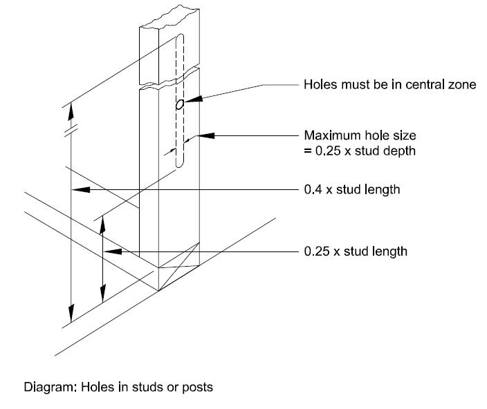
Refer to manufacturer’s recommendations for service holes in engineered wood joists.
Avoid the following defects:
• Insecurely fixed socket outlets, switches, cooker point boxes, etc.
• Electric power cables not derated where they run in or besides thermal insulation.
• Loadbearing studs cut away to accommodate meter boxes, flues, etc.
• Holes in vapour barriers around service pipes not sealed.
• Timber damaged by plumber’s blow torch.
• Metal sleeves not provided to flues.
• External and internal load bearing studs drilled or notched excessively.
213
12.0
214
215
INSULATED CONCRETE FORMWORK
13.0
13.0
INSULATED CONCRETE FORMWORK
Insulated Concrete Formwork (ICF) is an insulated solid wall, a relatively simple construction system that uses hollow block components. The components can be in the form of blocks, planks, panels or composites with planks or panels with tie devices to connect the inner and outer components. These components or blocks are typically of polystyrene (EPS) or ‘Woodcrete’ and are dry stacked together to provide a formwork system which is then filled with concrete and where necessary reinforced concrete to provide a solid, structural wall to transfer loads to the foundations. After the concrete has cured the formwork blocks remain in place to provide permanent, integrated, thermal insulation to both sides of the concrete core.
It should be noted, this guidance on ICF is for above ground superstructure works and not basements.
Expanded Polystyrene insulation (EPS) is manufactured using beads of polystyrene within a mould, steam is then applied directly to the beads which causes them to expand and fuse together, this process produces a closed cell structure, EPS moulds are lightweight will not sustain mould growth, and has no nutrient value to insects or vermin. EPS is non-hygroscopic and does not readily absorb moisture from the atmosphere. Its closed-cell structure reduces the absorption and/or migration of moisture into the insulation material.
Woodcrete forms are environmentally safe; do not contain or emit any toxic elements; and are fully recyclable; are vermin, termite, and insect proof and will not support fungus growth.
Accreditations
The system must have third party accreditation acceptable to ICW with its use and installation in accordance with the system’s certification. The design shall be by a suitably qualified structural engineer experienced in the use of ICF. A comprehensive structural design package will be provided to ICW along with the appropriate third-party accreditation.
The ICF system shall be supplied by a reputable supplier who is a member of the Insulating Concrete Formwork Association (ICFA).
The accredited installation company shall review and check all certificates and registrations, alongside thermal information of the ICF product.
The ICFA ensures all its members have suitable accreditation certificates and they have competent installers who have been fully trained in the installation of the ICF system.
216
13.0
ICF is a ‘shuttering or formwork system’ for concrete which is cast onsite. Whilst ICF blocks look like blocks, they are simply an insulated formwork (permanent - leave in situ shuttering with the added benefit of insulating properties).
The principle of various ICF systems is basically the same. However, they all have their own idiosyncrasies which must be taken into account. Therefore, it is essential that those involved in detailed design and construction must have attended a training course provided by an ICFA member to become fully conversant with the product.
217
Choose EPS or Woodcrete Engage with ICFA Member Choose ICFA Member www.icfa.org.uk Appoint an Architect Ground Engineer Attend and pass a Training Course Fully understand the system Gain ICW Approval Project Manager SAP Assessor Structural Engineer ICFA Member to oversee the first pour Commence Site 13.0
ICF
Key Elements of ICF
Structural design is the methodical appraisal of the stability, strength, rigidity and long-term integrity of structures. The basic objective in structural analysis and design is to produce a structure capable of resisting all applied loads and remain serviceable, without failure during its intended life.
The Structural design of an ICF structure should be conducted by a suitably qualified Structural Engineer / Engineering Consultancy, experienced in the use of ICF. Structural consultants should necessarily provide overall design, detailing and specification covering all structural aspects associated with the proposed ICF system and onsite safe construction, including vital areas such as, concrete strength (mix design), any steel reinforcement incorporation and lintel provision / reinforcement above openings.
An inspection should take place once the ICF formwork is in place – with the steel reinforcement exposed in-situ, prior to concrete pour. The qualified and competent person or company responsible for the overall installation and checking of the ICF aspect of the build, should always refer to the structural design, reinforcement schedules and layout documentation, in order to fully inspect and confirm correct and complete incorporation of vital components such as reinforcement bar types (e.g. T10 T12 T16 T20 T25 ) and position. Steel bar T12 for example is “H grade” high tensile steel reinforcement to BS4449/2005.
Shear Links to resist shear forces may be incorporated in vital structural elements such as concrete ring beams.
Lintels are commonly formed in-situ on ICF schemes, eliminating the need for RSJ’s (reinforced steel joists) that have a variety of names and styles – lintels, I/H/T beams, channel beams
Importantly the structural design should specify the type of concrete required to achieve the necessary strengths as per the engineer’s calculations. Mix design of concrete can be defined as the method of calculating a suitable quantity of constituent materials of concrete and finding out the required proportions with the object of producing concrete of certain minimum strength and durability as economically as possible. On-site concrete cube making and subsequent testing, may be required and should be clearly specified by the structural consultants at design stage.
It should be common practice for the installation company to require a copy of the concrete delivery batch ticket as part of the building sign off, as any future issues these can be relied upon and also prevents any ‘hand mixing of concrete’. A slump test should be carried out prior to the pour to ensure the correct consistency. A consignment ticket is a document that accompanies a batch of products as it moves through the manufacturing process. It typically contains information such as the product’s constituents, lot number, and date of manufacture.
Key elements are concrete strength, date, and delivery address are all recorded on the concrete batch ticket.
Continuity of insulation for the external perimeter must be checked by the installer to ensure no thermal ‘cold Bridging’ arises to elevations and other associated areas of the build. Structural fixity and cold bridge are two vital areas requiring thorough appraisal in such areas as balcony connections.
Manufacturer’s quality control procedures during installation and subsequent concrete pours and curing procedures should be rigorously followed. The installer should ensure adequate temporary propping of the ICF components during concrete pouring and curing. ICF products once installed and prior to and during concrete pours to be checked for dimension, level, alignment and square. Particular attention should be made to the accurate setting out of the first course, ensuring that the ICF wall is set out plumb & level across all planes.
Ongoing checks to be made on sealing of joints/gaps and bracing, especially to openings.
Concrete placement and associated compaction and vibration expels air and increases the density of concrete. It is of paramount importance that this is carried out successfully with ICF as any other form of concrete placement to avoid honeycombing within the concrete core.
When designing and constructing an ICF build, particular attention needs to be paid to the following areas and must be designed and detailed correctly to ensure compliance with ICW requirements.
218
13.0
TYPICAL EAVES/ WALL JUNCTION DETAIL


TYPICAL ROOF ABUTMENT/ PARAPET DETAIL


219 Insulated Concrete Form Internal plasterboard 150 x 150 mm air shield membrane ICF ceiling technology Damp proof membrane Thermal loft insulation Sealant or frame seal bead ICF render system with basecoat, reinforcing mesh, primer & top coat Standard Detail Drawing Oct 2022 NTS K. Millward EUD-20-I Roof Trusses Isometric Detail Flashing with 40 mm minimum overhang ICF lintel closer Insulated Concrete Form Compriband sealing tape ICF render system with basecoat, reinforcing mesh, primer & top coat Self adhesive non-woven fleece membrane Bellcast bead with mesh 150 mm above roof Plasterboard Hollow core pre-cast slab Flat roof covering to Wall panel anchor Standard Detail Drawing Oct 2022 NTS K. Millward EUD-22-I Hollow Core Precast Roof Isometric Detail
13.0
TYPICAL SERVICE PENETRATION DETAIL
Additional reinforcing mesh to overlap the stone wool lamella by 65 mm min. Insulated Concrete Form
ICF render system with basecoat, reinforcing mesh, primer & top coat
TYPICAL WINDOW REVEAL DETAIL


ICF render system with basecoat, reinforcing mesh, primer & top coat
Render corner bead


ICF EPS removed around the penetration and replaced with stone wool lamella adhesively fixed directly to the concrete core


Fire rated caulking Service penetration pipe with weathertight collar sealed to render basecoat with sealant
Intumescent firestop sealant


Insulated Concrete Form


Render stop bead with sealant


ICF end cap
Compriband sealing tape
Render basecoat


Plasterboard


220
Standard Detail Drawing Oct 2022 NTS K. Millward EUD-25-I Firewall Service Penetration Isometric Detail
Standard Detail Drawing
NTS K. Millward EUD-28B-I Window Reveal Detail Isometric Detail
Oct 2022
13.0
TYPICAL HORIZONTAL FIRE BREAK/ CAVITY BARRIER DETAIL”


ICF render system with basecoat, reinforcing mesh, primer & top coat


Additional layer of reinforcing mesh lapping 65 mm min. each side of the stone wool lamella
ICF render system with basecoat, reinforcing mesh, primer & top coat


Vertical fire barrier - stone wool lamella insulation classification A1, minimum 100 mm wide adhesively bonded to concrete using render base coat fully buttered to the back of the lamella stone wool


Additional layer of reinforcing mesh lapping 65 mm min, each side of the stone wool lamella


TYPICAL VERTICAL FIRE BREAK/ CAVITY BARRIER DETAIL


Timber floor joists with ICF hanger system
Horizontal fire barrier - stone wool lamella insulation classification A1, minimum 100 mm wide adhesively bonded to concrete using render base coat fully buttered to the back of the lamella stone wool


Intermediate
construction
floor
Insulated Concrete Form
Standard Detail Drawing Oct 2022 NTS K. Millward EUD-31B-I Horizontal Fire Break Isometric Detail
Concrete Form Plasterboard
Insulated
Standard Detail Drawing Oct 2022 NTS K. Millward EUD-31A-I Vertical Fire Break Isometric Detail
13.0
TYPICAL ILLUSTRATIONS OF WOODCRETE
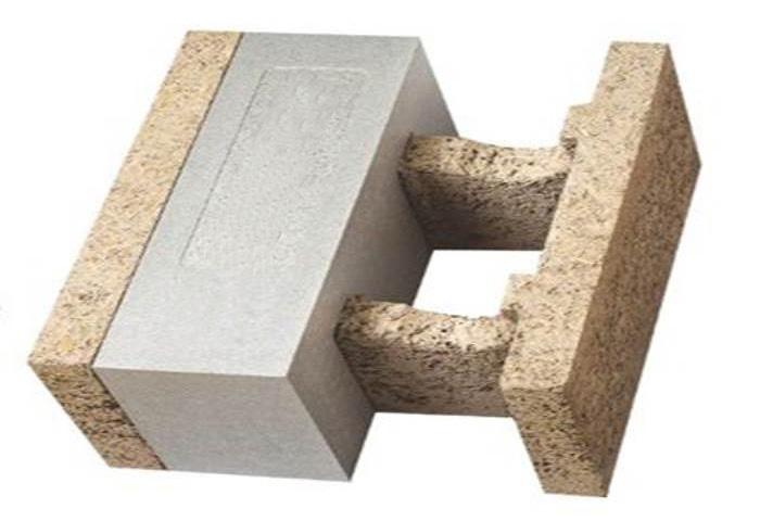
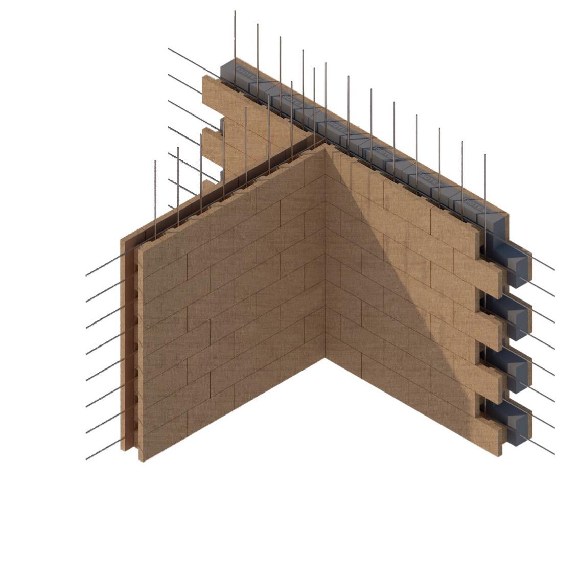
The ICF system should contribute to maintaining continuity of thermal insulation at junctions with other elements and minimise thermal bridges and air infiltration. Detailed guidance can be found in the documents supporting the applicable Building Regulations. Accredited u-values for a number of common junction types are available from the members of the ICFA.
Walls formed from the system can achieve adequate resistance to unwanted air infiltration provided there is effective sealing around junctions and penetrations. Completed buildings are subject to pre-completion testing for airtightness in accordance with the requirements of the Building Regulations.
222
13.0
Weathertightness
Resistance to weather is provided by the external finishes. Care should be taken to ensure the design and construction comply with the good practice described in the relevant building regulations and the ICF suppliers’ installation procedures.
The use of materials to form the weatherproof envelope should have the relevant third-party accreditation and be acceptable to ICW.
Stone or brickwork/blockwork should have a minimum of 50mm cavity to allow removal of debris. Ties should be of suitable length to allow fixing into the concrete core of the ICF.
Timber cladding is to be adequately ventilated and drained via a 20mm cavity. Further protection of the ICF may be required for open timber boarding. Again fixings into the concrete core of the ICF system is required.
External wall insulation and render systems must have third party accreditation acceptable to ICW to be suitable for the particular exposure and for the use with ICF.
All penetrations through the weatherproof skin should be sealed with a suitable fit-for-purpose sealing system. Particular attention is also required for the detailing of weatherproofing around external door and window openings. The reliance on mastic alone is not acceptable. Adequate detailing and the use of approved gaskets, DPCs and proprietary closers is required.
The ICF system components will not transmit moisture by capillary action. The concrete wall formed with the system should be constructed using the specified concrete recommended by the ICF supplier. The provision of horizontal DPCs must be appropriate to both the ICF system and weatherproof envelope. Where required, the damp proofing of the wall constructed from the system must be continuous with the damp proof membrane provided in the floor and must achieve continuity with any membrane or DPC provided in the external finish of the wall.
Particular attention is required to areas where abutments take place amongst others with lean-to flat roofs and parapets. Details to be provided on how these junctions have been designed to prevent the water penetration into the building.
Fire Protection
The EPS component of the system has a reaction to fire classification of E in accordance with BS EN 13501-1: 2018; therefore, the system is limited for use in buildings subject to height restrictions dependent on location within the UK or Europe.
The risk of fire spread over the wall surfaces will depend on the finishes and weathering envelope used. The relevant requirements of the Building Regulations must be observed.
Care must be taken to ensure that all detailing at junctions, including internal wall/floor junctions, adequately maintains the required periods of fire resistance. Any cavities formed in the completed walls or service entry points are appropriately fire stopped and detailing around any openings provide sufficient protection particularly at the junctions of separating compartment walls and floors. The EPS on the interior face should be discontinuous across separating wall / floor junctions. Fire barriers must completely seal any cavity and when EPS systems are used, to be chased into the outer EPS formwork to the outer face of the ICF concrete core.
223
13.0
224
225
14.0 MODERN METHODS OF CONSTRUCTION ICW Endorsed
14.0
14.0 ICW ENDORSED
ICW Endorsed –
Our modular & off-site system approval scheme
Our bespoke ICW Endorsed accreditation scheme will assist you in gaining pre-approval of your Modern Methods of Construction (MMC) system for use on your ICW Structural Warranty projects.
The scheme will ensure your MMC system meets our Structural Warranty requirements in line with our technical manual.
Why is accreditation required?
Specific MMC properties will require accreditation to our ICW Endorsed scheme before we are able to register them for cover under our Structural Warranty policy scheme.
Once endorsed, your MMC system (subject to terms and conditions) is now pre-approved for use across multiple projects.
ICW Endorsed registration is not recognised as a third-party accreditation and is used exclusively for systems that meet the requirements for ICW Structural Warranty purposes.
What we accredit
In general terms, there are two categories of MMC which are required to undergo our accreditation process:
• Modular System
Fully completed individual units with connection to foundations and services
• Modular Closed Panel System
Completed units/sections/panels with localised weathering not yet completed at junctions & still requiring service connections & localised making good internally
Other forms of MMC products as defined in the MHCLG Joint Industry Working Group The MMC Definition Framework 2019 will not require assessment under this scheme as these products may have third-party certification already and only form part of the overall build e.g. ICF, concrete flooring planks, SIPs.
Only certain products within the following three Framework categories will be required to undergo assessment under ICW Endorsed. This will be identified during the initial Desk Top Study stage of our application process.
226
The applicable categories in The MMC Definition Framework – March 2019 are;
Off-site and near site pre-manufacturing:
Category 1 Pre-manufacturing (3D primary structural systems)
“A systemised approach based on volumetric construction involving the production of three-dimensional units in controlled factory conditions prior to final installation. Volumetric units can be brought to final site in a variety of forms ranging from a basic structure only to one with all internal and external finishes and services installed, all ready for installation.
The system includes structural performance. Full volumetric units in apartment buildings can include apartment space and common area space. Mini volumetric structural units can include bathroom pods and the like which are structurally stacked and loaded.”
Category 2 Pre-manufacturing (2D primary structural systems)
“A systemised approach using flat panel units used for basic floor, wall and roof structures of varying materials which are produced in a factory environment and assembled at the final workface to produce a final threedimensional structure….
More complex panels – typically referred to as closed panels – involve more factory-based fabrication and include lining materials and insulation. These may also include services, windows, doors, internal wall finishes and external claddings. The system includes structural performance for primary walls and all floors (note – this excludes unitized or composite external walling systems that are not load bearing included in Category 5).”
Category 5 Pre-manufacturing (non structural assemblies & sub-assemblies)
“A series of different pre-manufacturing approaches that includes unitised non-structural walling systems, roofing finish cassettes or assemblies (where not part of a wider structural building system), non-load bearing mini-volumetric units (sometimes referred to as ‘pods’) used for the highly serviced and more repeatable areas such as kitchens and bathrooms, utility cupboards, risers, plant rooms as well as pre-formed wiring looms, mechanical engineering composites, would fall into this category.
Conventional masonry site constructed schemes utilising conventional building products such as windows and door-sets – which might otherwise be part of the fabrication process in the other premanufacturing categories – should not be included as sub-assemblies or components in this category unless there is a further level of consolidation from traditional configurations. Also excludes any structural base elements that composite assemblies are fixed to and which are to be included in Cats 1-4. Any structure in this category is purely to support the subassembly in transit / install phase.”
227
14.0
The accreditation process;
We will need to carry out a technical assessment of your MMC system to ensure conformity with our technical standards. This will include a Desk Top Study review followed by an initial inspection audit at each of your manufacturing facilities and storage locations.
This will involve us undertaking a review of your system design information, material & system certifications and production processes. We will also look at how your system will be installed on-site and performs when in-use.
If we are satisfied that your MMC system meets our requirements, we will then endorse it for use on ICW Structural Warranty projects. ICW Endorsed registration will be subject to terms and conditions which includes a framework of ongoing inspection audits.
The flow chart overleaf shows you the various process stages, from your initial application through to our decision to approve, or unfortunately on some occasions declinature.
Below, we have set out how we can help each other to streamline the assessment process.
What are we looking for?
In order to understand your project, we need to know as much as possible about it as soon as possible.
In particular, we need to see your:
• Project specification – plans and specifications.
• Structural adequacy of elements and confirm life expectancy of building – plans, specifications, calculations & any reports.
• Experts reports – these will be in addition to the structural engineer’s design and should include specialist reports on damp proofing/tanking systems.
• Where the structural elements of a MMC are designed by more than one expert, then one expert should be nominated to be responsible for certifying the overall stability of the structure.
• Independent assessment of components or system from BBA, BRE, WIMLAS or conformity to International, European or British Standards.
• Guidance from industry bodies, TRADA, CIBSE, CIRIA etc.
• Fire resistance and any third-party forms of certification.
• Past performance of proposed system and maintenance requirements.
• Test evidence.
• Third-party Manufacturer’s Warranties.
By providing us with all the relevant information at the point of your application, we will be able to complete our Desk Top Study without delay and, subject to Concept Endorsement In Principle, arrange for an initial inspection audit(s) of your manufacturing facilities and storage locations by our ICW Surveyor.
What we expect
• All external walls must prevent moisture penetration to the inside and be insulated to building regulation requirements. This can be achieved with a suitable system, which will both insulate the fabric of the structure and externally applied render/ insulation system.
• Any habitable areas either below or partially below ground level must be provided with a minimum Grade 3 waterproofing system with ventilation, dehumidification or air conditioning necessary, appropriate for the intended use. Designers of such below ground waterproofing systems shall be experienced in waterproofing systems and hold an appropriate qualification i.e., CSSW.
• All repairs and treatments identified in the expert’s and engineer’s reports.
• In addition to the contractor’s guarantee, a minimum 10 no. year insurance backed guarantee is required for chemical DPCs, specialist and flat roofing systems and proprietary externally applied weather proofing/insulation systems.
• Windows, doors and internal services should be to modern standards.
• Life of building to be at least 60 no. years in accordance with UK Finance requirements. The market acceptance benchmark for structural lifespan is 60 no. years when used as part of the structure. However, it is also accepted that materials that are not of the structure will require maintenance and or replacement within this period.
228
14.0
229
ICW ENDORSED
How to apply
Fill in our ICW Endorsed System Review Application Form online, we will then contact you and provide you with further information.
Please contact ICW should you have any questions regarding our ICW Endorsed modular & off-site system approval scheme.
FLOW
CHART ICW ENDORSED
01
Application for ICW Endorsed
MMC Application submitted to ICW
05
Initial Inspection Audit(s)
Initial inspection audit(s) of manufacturing facilities & storage locations carried out by ICW Surveyor
Outcome - No action required OR action required
02
Desk Top Study Review
Desk Top Study Review undertaken by ICW Technical Services Team (TST)
Any additional information requested by TST provided by applicant
Completion of Desk Top appraisal 06
Decision in Full
No action required OR action resolved > ICW Endorsed
Action unresolved > ICW Endorsed
230
14.0
03
Initial Decision in Principle
MMC Concept Endorsed in Principle by TST (or declined)
Quotation & Terms and Conditions issued
Payment & signed Terms and Conditions received 07
Ongoing Inspection Audits
Further facility & storage inspection audits carried out by ICW Surveyor
Outcome - No action required OR action required
No action required OR action resolved > ICW Endorsed maintained
Action unresolved > ICW Endorsed withdrawn
04
Application for ICW Structural Warranty
MMC Concept Endorsed in Principle recognised as part of our Structural Warranty scheme
Structural Warranty Application submitted to ICW
Quotation & Terms and Conditions issued to Developer/Builder
Payment & signed Terms and Conditions received
Structural Warranty process to be followed
08
Annual Renewal
Renewal Questionnaire issued to registered accreditee
Returned Questionnaire reviewed by TST
Any additional information requested by TST to be provided
ICW Endorsed renewal confirmed (or ICW Endorsed withdrawn)
Quotation & Terms and Conditions issued
231
14.0
232
233
SERVICES
15.0 INTERNAL
15.0
15.0 INTERNAL SERVICES
Statutory Requirements
Building Regulation Requirements
The requirements of the Approved Documents of the Building Regulations should always be followed, and all the relevant approvals sought from the Building Control Body.
If any calculations are required to support the proposed design, then these should be provided by a suitably competent and qualified person. The calculations will need to be designed so as they safely distribute loads and forces to the foundations.
Workmanship
During the construction phase:
• All workmanship must be completed in a competent workmanship like manner.
• Protected against unnecessary damage.
• Design and Installation specifications are followed.
• Products and materials are inspected for suitability for their purpose.
Materials
All materials used shall:
• Be adequately protected and stored in a correct manner.
• Comply with relevant British Standards or equivalent European Technical Specification with the certification available for inspection by ICW.
• Be installed as per Manufacturers details.
• Have a life span of 60 years when used as part of the structure, however it is accepted that materials that are not an integral part of the structure may require maintenance and or replacement within this period.
Design
Where a specialist design is requested or required, they shall:
• Be designed by a suitably qualified person.
• Be supplied with clear precise instructions.
• Be supported with structural calculation when outside the guidance of the Approved Documents.
• Be available for inspection by ICW.
Water Services and Supply
Service supplies and installations should be designed by an expert, considering the required pressures and flow rates from the incoming mains, detailed drawings should be available for inspection.
Protection from Freezing
Where water services are located within unheated spaces it is important to reduce the risk of freezing, insulation should be installed it is accepted that minimum insulation thickness of 24mm will be adequate for the prevention of freezing to domestic installations.
234
Hot Water Services
Hot water supply may be provided from an instantaneous source such as a combi boiler or the provision of a storage system, where a cylinder is installed it must have the access to all relevant parts as specified in the installation manual for maintenance, any pipe work installed in uninsulated spaces must be insulated to prevent freezing. Hot water services are to be designed with the following min flow rates:
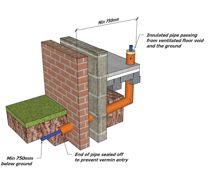
235 15.0
Location Min Flow Rate (l/s) Temperature°C Bath Tap 0.3 50 Wash Hand Basin 0.15 50 Shower 0.1 40 Sink 0.2 60
Unvented Hot Water Systems
Where an unvented system is installed it must be accompanied with a third-party accreditation and the installation completed by a competent person. To minimize the danger from excessive pressure, the systems should include a min of two independent safety devices, this is in addition to any thermostat provided to control the desired temperature of the stored water, the design of the safety devices should also take into consideration the location and configuration of the devices.
Unvented systems should be indelibly marked with the:
• Manufacturers details.
• Model reference.
• Rated storage capacity.
• Operating pressure of the system and expansion valve.
• Relevant operating data on each safety devices fitted.
• The max primary circuit pressure and flow temp of indirect hot water storage system units or packages.
In addition, a warning sign should be indelibly marked on the hot water storage system unit or package so that it is visible after installation.
Examples of acceptable discharge arrangements are:
• To a trapped gully with the end of the pipe below fixed grating and above water seal.
• Downward discharge at low level, up to 100mm above external surfaces such as car parks, hard standings etc, are accepted providing that a wire cage or similar guard is positioned to prevent contact whilst maintaining visibility.
• Discharge at high level into a metal hopper and metal downpipe with the end of the discharge pipe clearly visible or onto a roof capable of withstanding high temperatures and 3m from any plastic guttering system that would collect such discharges.
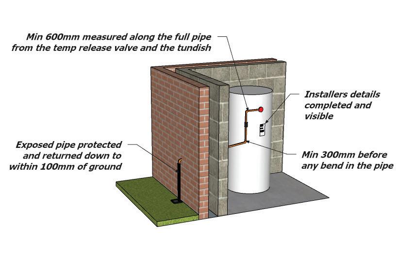
236
15.0
Electrical
Electrical installations should be in-line and comply with the IEE Wiring Regulations and BS7671, Installations should be registered with a recognised body such as NICEIC and a certificate should be issued on completion.
There is a requirement to supply outlets to rooms as identified below:
For structural stability avoid back to back chasing, and chasings should be fully filled with mortar prior to covering.
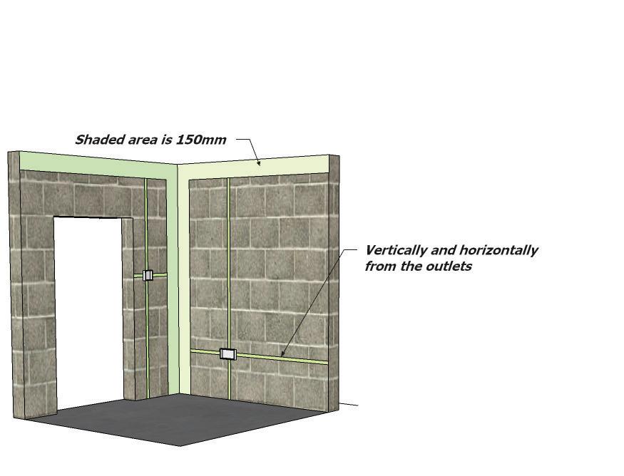
Cables that are not protected by a conduit should be located horizontally or vertically from the outlets within the green area of the diagram and a minimum of 50mm from the surface of the wall.
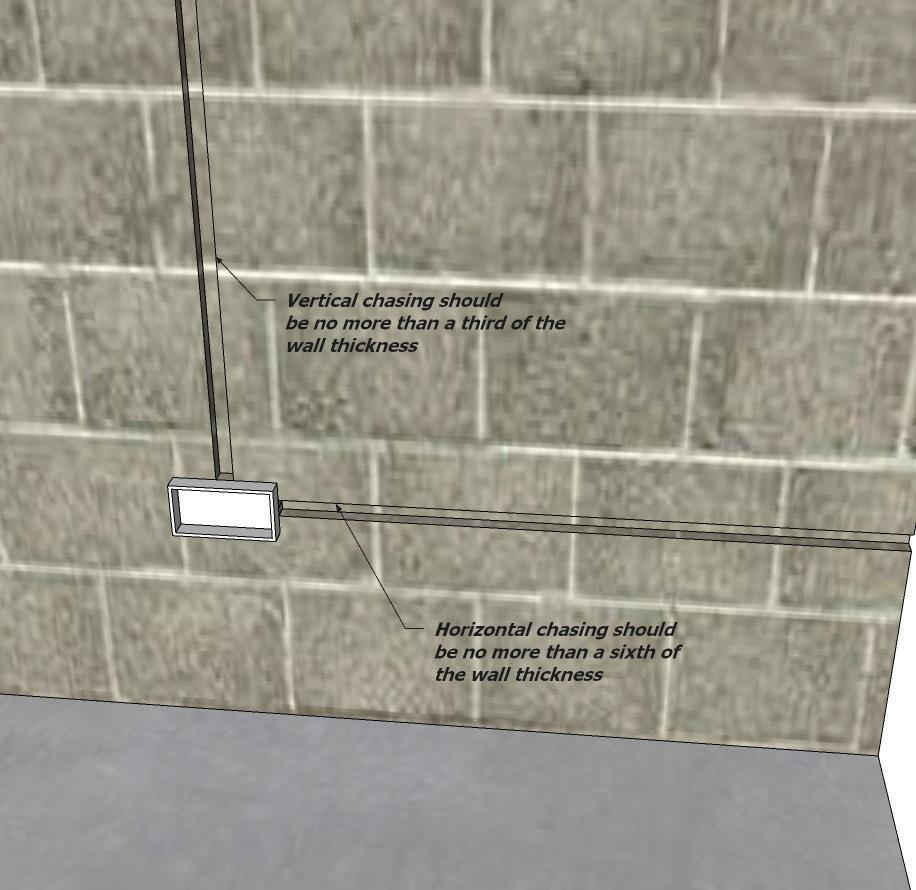
237
Room Outlets Living Room 8 Dining Room 3 Kitchen 8 Utility 2 Double Bedroom 6 Single Bedroom 4 Hall/Landing 2 Loft 1
15.0
15.1 SPACE HEATING
Space heating systems should comply with the appropriate following British standards and codes of practice:
BS5410 Code of practice for oil firing
BS5449 Specification for forced circulation hot water central heating systems for domestic premises
BS5482-1 Code of practice for domestic butane- and propane-gas-burning installations
BS5864 Installation and maintenance of gas-fired ducted air heaters
BS5871-1
BS6700
Specification for the installation and maintenance of gas fires, convector heaters, fire/back boilers and decorative fuel effect gas appliances
Design, installation, testing and maintenance of services supplying water for domestic use within buildings and their curtilages
BS8303 Installation of domestic heating and cooking appliances burning solid mineral fuels
Whole home heating systems should be designed to provide internal temperatures as shown below with an assumed external air temperature of -3 degrees:
238
Code of Practice
Code
Location Temperature in Degrees Air changes Living Room 21 1.5 per hour Dining Room 21 1.5 per hour Kitchen 18 2 per hour Bedrooms 18 1 per hour Bathroom 22 2 per hour Separate WC 18 2 per hour Hall and Landing 18 2 per hour
15.1
15.2 WINDOWS AND DOORS
Windows and Doors
All external timber should be a species classified as suitable in BS EN 942 and meet the requirement found in TRADA Wood Information Sheets 3.10 and 4.16. Products which are not constructed of timber i.e. Aluminium, Glass and UPVC should meet the requirements of the following:
• BS 4873 Aluminium windows.
• BS 5286 Specification for aluminium framed sliding.
• BS 6510 Steel windows and doors; • BS 7412 PVC-U windows; • BS EN 514 PVC-U windows. All doors should meet the requirements of the buildings SAP calculation and should also ensure that adequate means of escape and ventilation are available.
239
15.2
15.3 ESCAPE WINDOWS
Means of Escape
Approved Document B requires that escape is required from every habitable room and this will be achieved by installing windows with a clear openable area of 0.33m2. This can be achieved by ensuring at least one dimension has a minimum of 450mm wide. The access to this window cannot be higher than 1100mm from the floor level.
Protection from Falling
Guidance found in Approved Document K2 specifies a minimum guard height of 800mm to window openings in the external wall. It is advisable that where possible windows are installed higher to prevent guarding. However, in the situation where guarding is required, and the openable area of the window is less than 800mm the window will require permanent guarding to BS 6180.
Installation and Workmanship
As soon as possible windows and doors should be installed to ensure the water tightness of the building. All the windows and doors should be to the correct sizes, dimensions, specifications and should be installed as per manufacturer’s details. There should be no gap greater than 10mm around the opening, and for gaps less than 5mm the sealant should cover the frame and the masonry by 6mm to ensure weather tightness.
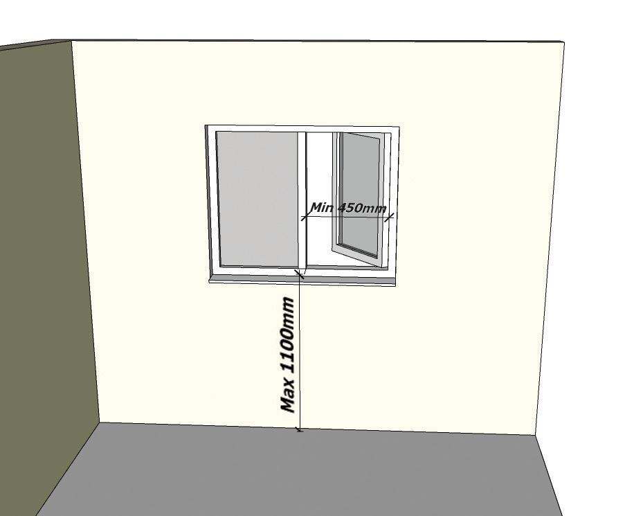
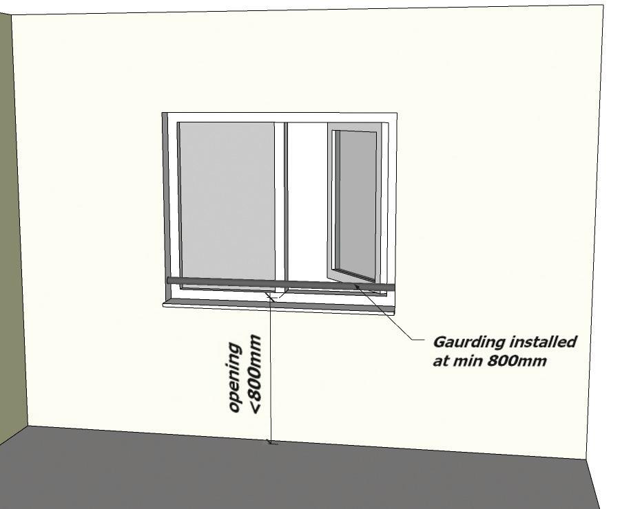
240 15.3
15.4 SAFETY GLAZING
Safety Glazing for Critical Locations
In all cases the minimum requirement of Approved Document K (4) of the Building Regulations 2013 Protection against impact with glazing must be followed.
K4.—Glazing, with which people are likely to come into contact whilst moving in or about the building shall:
• If broken on impact, break in a way which is unlikely to cause injury; or
• Resist impact without breaking; or
• Be shielded or protected from impact.
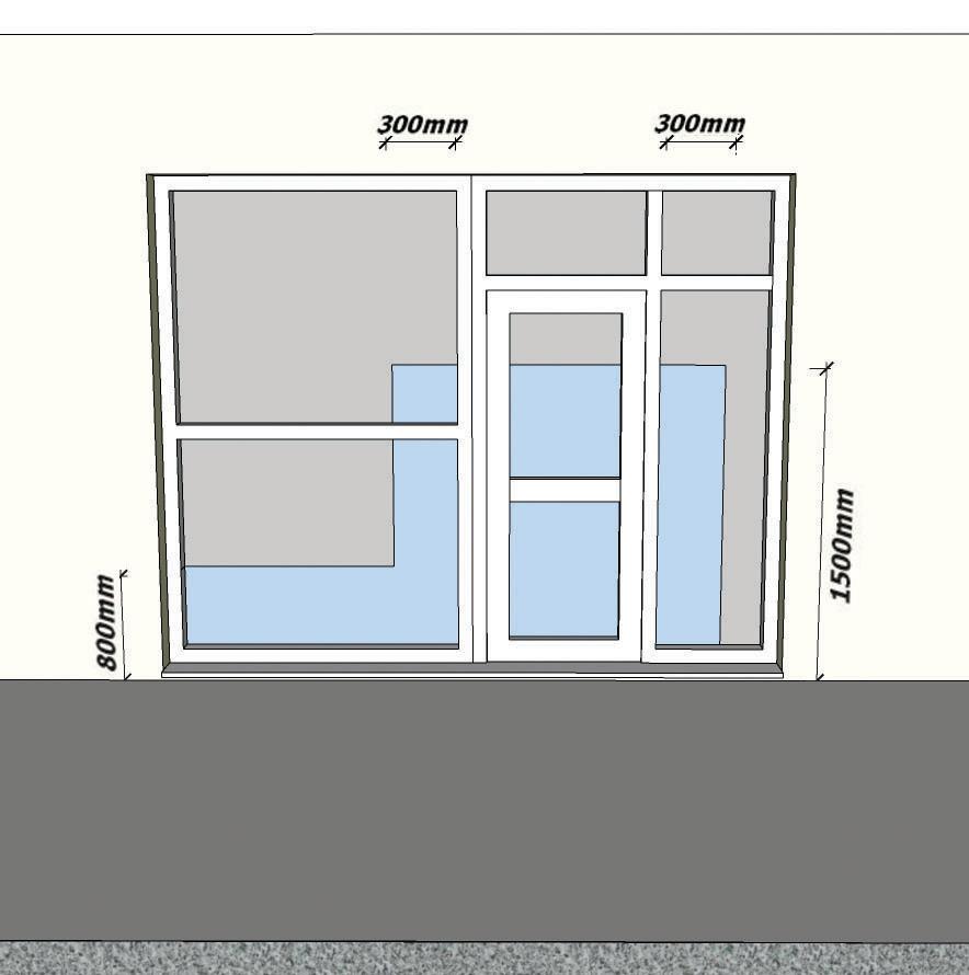
241 15.4
242
243
16.0 CONVERSION
16.0 INSPECTION PROCESS
ICW will carry out targeted inspections on all converted and refurbished properties. The main purpose of carrying out inspections is to reduce the risk of latent defects through a tightly targeted programme of risk management. Each development being assessed on its merits including; the complexity of the site, site environment, method of construction and the experience of the developer / builder.
When registering your site with us, you will receive contact details of your allocated ICW surveyor or appointed approved inspector, with who you can arrange your first site visit. In order for us to gather a full understanding of your development and what you wish to achieve, your appointed surveyor will arrange a pre-planning meeting with your site manager with the purpose of discussing the development as a whole, including programme of works and the method of construction. Following this meeting your appointed surveyor will discuss your risk management programme, targeting site inspections to suit the agreed stages of the development.
Our Inspection programme of risk management cannot eliminate all risks but together with the following stage inspection memoirs will endeavour to: -
• Reduce any uncertainties.
• Minimise the risk of defects going undetected.
• Increase satisfaction of the new building user.
• Reduce the likelihood of claims e.g. For the Builder/ Developer during the two-year defect liability period and for the End Insurer of the Policy.
The number of inspections carried out on the construction of your development will vary depending on initial and on-going risk management assessments carried out by your appointed surveyor. These occur at three different stages throughout the course of the build in order to identify areas where assistance can be given to reduce the number of latent defects at each stage of construction. Your appointed surveyor will carry out at least three inspections throughout the build, however, the amount and frequency of inspections will vary depending on the complexity and speed of construction.
The programme of risk management inspections is planned to cover all significant structural and weather penetration elements. At each inspection, your appointed surveyor records all the data gathered and provides a site generated report for each plot where technical advice is given, or a defect is recorded. The following inspection overview will indicate the elements of construction that should be completed and will allow the site manager to check works during the build to completion and provide an indication into the aspects of construction your appointed surveyor will want to inspect.
The recorded information is held by ICW providing an on-going record of information for each plot. This provides an invaluable source of management data and, as a unique service to our clients; we can offer a regular reporting service.
Please note: Works that are not acceptable to ICW will require rectification before an Insurance certificate can be produced.
244 16.0
Conversion Construction Stage’s Site Overview Commencement of site/Site Overview Initial Inspection Foundations (If applicable) & Strip out of existing structure Intermediate Inspection Superstructure to Roof including pre-plaster Completion Inspection Final Inspection prior to Handover
16.1 SITE AND CONTSTRUCTION OVERVIEW
General – The ICW surveyor will check all details on-site are identical to those quoted and uploaded onto the Smartsurv Inspection Application i.e. Plot numbers, site address, contact details etc.
ICW surveyor to introduce themselves and to take note of site agents name and contact details.
Check that all proposed plots under the current phase have been registered and that the plot numbers on- site are as those described on the SmartSurv application.
ICW surveyor to explain the on-site paperwork and inspection recording system.
Site wide elements - the ICW surveyor will discuss the type of construction to be adopted together with general observations on the ground conditions, foundation type and site wide elements.
The ICW surveyor will discuss the principles of the development on the following issues:
Construction type
Traditional or non-traditional or Modern Methods of Construction.
Exposure conditions of the Site
Have they been considered in the design.
Are there any rooms to be constructed below ground? (habitable or non habitable and if so, are insurance backed guarantees going to be provided).
Ground conditions:
- type of subsoil
- water table level
- contaminants, gas etc
- shrinkability if clay and trees (present or removed)
- foundation design (standard / engineered)
- difficult site condition i.e. sloping site
- land drainage required
Sound insulation:
- are RSD’s to be used, unique numbers required
- pre completion testing is this by UKAS or ANC member
- from Approved Doc E pre completion testing required Is this by UKAS or ANC member
245
Item of construction to be quality checked Builder Check ICW Inspect
16.1
General – The ICW surveyor will check all details on-site are identical to those quoted and uploaded onto the Smartsurv inspection application i.e. plot numbers, site address, contact details etc.
Foundations discussed in detail to establish the type and design (only applicable if new foundations are part of the new works):
- strip - raft - piled
- underpinning
- other - existing ground obstructions
- sulphates in the ground (cement considerations)
Tanking:
- are there any walls to be tanked or require tanking
- are there any basement areas and what is proposed to prevent water ingress, attention to detailing of junctions
- structural design, wall, floor construction
- ventilation, fire resistance and means of escape in case of fire
- services passing through and land drainage around perimeter - is an Insurance backed Guarantee to be provided
Drainage:
- mains drainage, foul and surface water
- MH size and location, gradients and protection
- non-mains drainage
- septic tank / treatment plant / cesspool
- size and location - vehicular access required
- outfalls and porosity tests
- soakaways - size, location and ground conditions (porosity tests)
- land drainage
Ground floor type:
- ground bearing - beam and block or similar type
- cast insitu concrete - timber
246 Item of construction to be quality checked Builder Check ICW Inspect
16.1
General – The ICW surveyor will check all details on-site are identical to those quoted and uploaded onto the Smartsurv inspection application i.e. plot numbers, site address, contact details etc.
External wall type:
- masonry cavity / solid - timber frame - steel frame
- concrete frame / panel / other
External wall insulation:
- full fill
- Partial fill - clear - other
Movement joints: - location
- type/design - restraint
Internal walls:
- partition walls
- type, loadbearing / non loadbearing
- foundations - party walls - masonry - solid - cavity - dry lined or dense plaster - timber framed - metal framed - other
247 Item of construction to be quality checked Builder Check ICW Inspect
16.1
General – The ICW surveyor will check all details on-site are identical to those quoted and uploaded onto the Smartsurv inspection application i.e. plot numbers, site address, contact details etc.
Upper floors:
- floor type - timber, concrete, other - spans
- fire resistance
- insulation
Party floor:
- floor type - timber, concrete
- sound performance
- density or isolation
Roof - pitched, flat, mansard, other:
- timber, steel, other
- trusses or cut
- fixing details
Roof covering:
- slates, tiles, thatch, high performance felts, lead, other
- fixing specification - nailing / clipping, manufacturers details
- roof penetrations
- chimneys - stability and trays / flashings
- parapets / copings - stability and trays / flashings
- vents -flashings
- roof lights
- consider design, trimming and weathering
248 Item of construction to be quality checked Builder Check ICW Inspect
16.1
16.2 FOUNDATION TO GROUND FLOOR CHECKLIST
General – items checked during this inspection will cover the quality of build and structural stability / future weather integrity of the structure from foundation to ground floor level.
Foundations in place and constructed to comply with the Building Regulations and/or the relevant British Standards, checks made:
- strip - raft
- piled - underpinning
- existing ground obstructions
- sulphates in the ground (cement considerations)
Load bearing walls from foundation to dpc:
- bricks and blocks below dpc
- selection of bricks and resistance to ingress of moisture
Basements:
- ensure that all tanking is correctly installed and linked to the dpc and dpm above of the above ground structure
Floors - all floor substructures in place and constructed to comply with the Building Regulations and or the relevant British Standards, checks made for:
Timber:
- size, centres, spans and grading of joists
- fixings and bearings
- multiple and trimming members
- adequate ventilation
- restraint straps and noggins
- concrete
- size and bearing of units
- damaged units
- no cavity obstructions and trimming of openings
- adequate support to internal partitions and service entries filled
- all dpcs linked to suitable dpm’s
249
16.2 Item of construction to be quality checked Builder Check ICW Inspect
General – items checked during this inspection will cover the quality of build and structural stability / future weather integrity of the structure from foundation to ground floor level.
Walls - all walls to be plumb and structurally stable, checks made for:
Masonry:
- dpcs lapped and bedded on a smooth joint
- dpcs in place around all openings
- wall ties correctly specified and placed
- joints filled and consistent in width and height
- cavities free of debris
- insulation correctly located, secured and clean
- lintel bearings and beam supports correct
Timber / steel frame system:
- sole plate preparation and fixing adequate
- plumb
- correct specification used in make up
- cavity barriers correctly located
- damage, notching and drilling of members
- wall ties and lintels suitable for purpose
- breather membrane intact
Internal walls:
- built off adequate support
- masonry joints filled
- bonding adequate
Lintels and bearings
250 Item of construction to be quality checked Builder Check ICW Inspect
16.2
16.3 STRIP OUT & ASSESSMENT OF ORIGINAL STRUCTURE CHECKLIST
General – items checked during this inspection will cover the quality of build and structural stability / future weather integrity of the structure from foundation to ground floor level.
Walls - all walls to be plumb and structurally stable, checks made for:
Masonry:
- dpcs lapped and bedded on a smooth joint / proprietary damp proof measures
- dpcs in place around all openings / proprietary damp proof measures
- lintel bearings and beam supports correct
Timber / steel frame system:
- sole plate preparation and fixing adequate
- plumb
- decayed timber / replacement
- cavity barriers correctly located
- damage, notching and drilling of members
- breather membrane intact
Internal walls:
- built off adequate support
- masonry joints filled and bonding adequate
Lintels and bearings
Floors - all floor substructures in place and structurally stable, checks made for:
Timber:
- size, centres, spans and grading of joists
- decayed timber / replacement
- adequate ventilation
- restraint straps and noggins
Concrete:
- size and bearing of units
- damaged units
- no cavity obstructions and trimming of openings
Adequate support to internal partitions
251 16.3
Item of construction to be quality checked Builder Check ICW Inspect
General – items checked during this inspection will cover the quality of build and structural stability / future weather integrity of the structure from foundation to ground floor level.
Roofs (internally) - all roofs to be weathertight and structurally stable, checks made for:
- centres and sizes of joist, binders, purlins, struts and or trusses
- decayed timber / replacement
- fixings of timbers / members
- trimming to openings
- proximity of timbers to chimneys/ flues
- damage and or notching / drilling
- restraint straps and noggins in place
- bracing - size, location and fixing
- valley, hip and dormer roof details
- penetrations and weathering
- party and gable wall cut to profile and fire stopped (where applicable)
- flue and vent connections
- felt condition and laps
- cross ventilation / warm roof detail
Roofs (externally):
- ensure that the batten sizes, spacing and fixings are compatible with the covering and each other
- all finishes (tiles, slates, lead or felt) should be free from damage, laid to falls where appropriate and finished to a basic visual standard
- all coverings should be nailed, fixed, clipped to the correct specification in accordance with the relevant British/European Standards or the manufacturers
- original materials to be retained/altered or replaced
Miscellaneous:
- Staircases - ensure that the staircase has a minimum suitable width, the correct headroom, pitch, riser and going, together with a correctly located and fixed handrail and balustrading
- fireplaces, hearths and chimneys properly constructed
- windows – to be retained/altered or replace
252 Item of construction to be quality checked Builder Check ICW Inspect
16.3
16.4 SUPERSTRUCTURE TO UPPER FLOOR
General - items checked during this inspection will cover the quality of build and structural stability / future weather integrity of the structure from dpc to upper floor level.
Walls - all walls to be plumb and structurally stable, checks made for:
Masonry:
- restraint straps and noggins in place
- dpcs suitably lapped and bedded on a smooth joint
- dpcs in place to all openings
- insulation correctly situated, secured and clean
- wall ties correctly specified and placed
- joints filled and consistent in width and height
- lintel bearings correct and beam supports checked
- cavities free of debris
Timber / steel frame system:
- sole plate preparation and fixing adequate
- plumb
- correct specification used in make up
- cavity barriers correctly located
- damage, notching and drilling of members
- wall ties and lintels suitable for purpose
- breather membrane intact
253 16.4 Item of construction to be quality checked Builder Check ICW Inspect
General - always refer to the ‘Superstructure to Upper Floors (02) check list’ in addition to this list. Items checked during this inspection will cover the quality of build and structural stability / future weather tightness of the structure from upper floor level to, but excluding, roof construction.
Floors - all floor substructures in place and constructed to comply with the Building Regulations and or the relevant British Standards, checks made for:
Timber:
- size, centres, spans and grading of joists
- damaged units
- fixings and bearings
- multiple and trimming members
- restraint straps and noggins
Concrete:
- size and bearing of units
- no cavity obstructions
- trimming of openings
Party floors:
- joints filled
- correct density
- floating layer - junctions detailed
Adequate support to internal partitions
Service entries filled
254 Item of construction to be quality checked Builder Check ICW Inspect
16.4
General - always refer to the ‘Superstructure to Upper floors (02) check list’ in addition to this list. Items checked during this inspection will cover the quality of build and structural stability / future weather tightness of the structure from upper floor level to, but excluding, roof construction.
Walls - all walls to be plumb and structurally stable, checks made for:
Masonry:
- restraint straps and noggins in place
- dpcs suitably lapped and bedded on a smooth joint
- dpcs in place to all openings
- insulation correctly situated, secured and clean
- wall ties correctly specified and placed
- joints filled and consistent in width and height
- lintel bearings correct and beam supports checked
- cavities free of debris
Timber / steel frame system:
- sole plate preparation and fixing adequate
- plumb
- correct specification used in make up
- cavity barriers correctly located
- damage, notching and drilling of members
- wall ties and lintels suitable for purpose
- breather membrane intact
Walls, general:
- movement control
- appearance
- cladding
- thermal insulation and cold bridging
- cavity closed at eaves level
- wallplate bedded and fixed (where applicable)
- mortar correct specification
255 Item of construction to be quality checked Builder Check ICW Inspect
16.4
General - always refer to the ‘Superstructure to Upper floors (02) check list’ in addition to this list. Items checked during this inspection will cover the quality of build and structural stability / future weather tightness of the structure from upper floor level to, but excluding, roof construction.
Party walls:
- density / isolation adequate and maintained
- joints filled
- junctions detailed
- party wall sock to external cavity
- no mix and match of materials
- penetrations
- wall ties to correct specification
Chimneys and parapets - ensure that:
- all cavity trays and flashings are correctly situated (two number proprietary lead trays dressed up around flue)
- check liners correctly placed and joints sealed
- the chimney is correctly sized for stability and located the correct height above pitch line
- the masonry and the flaunching is correctly pointed
- copings correctly restrained / securely fixed
- cavity trays (stepped) correctly located and lapped into soakers and flashings
- mortar mix is suitable
256 Item of construction to be quality checked Builder Check ICW Inspect
16.4
16.5 UPPER FLOORS TO PRE PLASTER INCLUDING ROOF STRUCTURE
General - always refer to the ‘Upper floors to Pre-Plaster including Roof Structure (Intermediate Inspection) check list’ in addition to this list. Items checked during this inspection will cover the quality of build and structural stability / future weather tightness of the structure up to pre-plaster and including, roof construction. The structure may not yet be fully weather tight.
Floors - all floors (including party floors) in place and constructed to comply with the Building Regulations and or the relevant British Standard
Walls - all walls to be plumb and structurally stable, cavities free of debris
Roofs - all roofs to be constructed and structurally stable, checks made for:
- centres and sizes of joist, binders, purlins, struts and or trusses
- fixings of timbers / members
- trimming to openings
- proximity of timbers to chimneys/ flues
- damage and or notching / drilling
- restraint straps and noggins in place
- bracing - size, location and fixing
- valley, hip and dormer roof details
- penetrations and weathering
- party and gable wall cut to profile
- external wall insulation in place to prevent cold bridging and cavity closed at eaves level
- ensure that the batten sizes, spacing and fixings are compatible with the covering and each other
- cavity barriers provided where appropriate
Chimneys and parapets - ensure that:
- all cavity trays and flashings are correctly situated
- the chimney is correctly sized for stability and located the correct height above pitch line
- the masonry and the flaunching is correctly pointed
257
Item of construction to be quality checked Builder Check ICW Inspect
16.5
General - all structural items should be in place and completed, namely floors, walls, roof structure, staircases etc. In addition, all services, ‘first fix’, should be undertaken or almost complete.
Floors - all floors in place and constructed to comply with the Building Regulations and or the relevant European Standards, checks made for:
- holes within floors - fire stopping
- notching / drilling of joists
- damaged floor units
- fixing of boards / floating floors preparation
- vapour barriers
- party floors
- joints filled
- correct density
- floating layer
- junctions detailed
- adequate support to internal partitions
- plasterboard / plain edge board supports
- correct centres and sizes of joists
Walls - all walls to be plumb and structurally stable, checks made for:
- dpcs in place at all openings and linked to dpm at floor
- restraint straps and noggins in place
- chasing to walls for sockets and fittings
- party walls
- joints filled
- junctions detailed
- no mix and match of materials
- bearings to joist, lintels and beams
258 Item of construction to be quality checked Builder Check ICW Inspect
16.5
General - all structural items should be in place and completed, namely floors, walls, roof structure, staircases etc. In addition, all services, ‘first fix’, should be undertaken or almost complete.
Roofs (internally) - all roofs to be weathertight and structurally stable, checks made for:
- centres and sizes of joist, binders, purlins, struts and or trusses
- fixings of timbers / members
- trimming to openings
- proximity of timbers to chimneys/ flues
- damage and or notching / drilling
- restraint straps and noggins in place
- bracing - size, location and fixing
- valley, hip and dormer roof details
- penetrations and weathering
- party and gable wall cut to profile and fire stopped (where applicable)
- flue and vent connections
- felt condition and laps
- insulation (if fitted at time) - continuity with external wall insulation
- cross ventilation / warm roof detail
259 Item of construction to be quality checked Builder Check ICW Inspect
16.5
Services - generally all services and service paths should be fitted in accordance with the appropriate British Standard and/or governing bodies guidance.
Electrical - ensure that all works have been installed in accordance with the IEE Regulations. Checks made for:
- location of cable runs within floor and wall constructions - vertical and horizontal from sockets / switches
- need for earthed protection
- socket and switch heights
Gas / solid fuel - ensure that all works have been installed by a Corgi registered fitter. Checks made for:
- location and protection
- serviceability / access - ventilation
Plumbing - ensure all pipes are correctly clipped / fixed and protected.Check made for:
- location and sizing of pipes
- protection passing through walls / floors
- damage - backfalls - connections
260 Item of construction to be quality checked Builder Check ICW Inspect
16.5
Services - generally all services and service paths should be fitted in accordance with the appropriate British Standard and/or governing bodies guidance.
Miscellaneous:
- staircases - ensure that the staircase has a minimum suitable width,
the correct headroom, pitch, riser and going, together with a correctly located and fixed handrail and balustrading
- first fix carpentry in place, plumb and square - fireplaces, hearths and chimneys properly constructed - windows - frames appropriately fixed and glazing installed correctly
Conservatories - ensure that they are constructed to the same standard as the remainder of the home and form a weather tight and stable addition to the house. In addition, ensure that cavity trays are installed as per any other abutment.
Integral garage - ensure that it is finished internally to a reasonable, basic level of decoration appropriate for its intended use. It is weathertight (not necessarily watertight, 100mm brick wall) and where abutting the house incorporates a suitable cavity tray and flashing. Ensure firestopping is complete.
Basements - ensure that all tanking is correctly installed and linked into the cavity tray, dpc and dpm of the above ground structure.
261 Item of construction to be quality checked Builder Check ICW Inspect
16.5
Structure - ensure that brickwork / rendering and roof covering is of a consistent nature in quality of finish and workmanship. All window and door frames must be reasonably sealed where abutting the external envelope to prevent weather penetration.
External walls:
- rendering - should be durable to resist the weather and impact
- should not bridge the dpc
Masonry
- should be matched in colour and texture providing reasonable aesthetics
- joints should be filled / pointed and consistent
- mortar should be durable and consistent in colouring
- corbelling and or plinths should not be excessive, thus enabling water to collect
General
- movement joints should be suitably located and filled
- weepholes should be evident at all locations of cavity projections and at dpc level within timber frame construction
- ensure that surfaces are reasonably plumb and level
- lead flashings should be correctly located and fixed
- dpc should not be bridged and located a min. 150mm above finished external ground level
Level thresholds
Should be suitably constructed to prevent damp ingress and allow adequate entry to the dwelling via a wheelchair
262 Item of construction to be quality checked Builder Check ICW Inspect
16.5
Structure - ensure that brickwork / rendering and roof covering is of a consistent nature in quality of finish and workmanship. All window and door frames must be reasonably sealed where abutting the external envelope to prevent weather penetration.
Windows and doors:
- ensure that all windows and doors are
- suitably decorated to a reasonable visual standard and to provide weather protection to the home
- designed in such a way to shed water from the external envelope
- provided with a suitable deterrent against a forced entry
- ensure that brickwork and stone cills and heads shed water and are not damaged / cracked
Roofs (externally):
- ensure that the batten sizes, spacing and fixings are compatible with the covering and each other
- all finishes (tiles, slates, lead or felt) should be free from damage, laid to falls where appropriate and finished to a basic visual standard
- all coverings should be nailed, fixed, clipped to the correct specification in accordance with the relevant British/European Standards or the manufacturers’ details
- coverings and gauge are suitable for pitch
- all flashings and trays are correctly specified and positioned
Chimneys and parapets - ensure that:
- all cavity trays and flashings are correctly situated
- the chimney is correctly sized for stability and located the correct height above pitch line
- the cowling is correctly fitted (where applicable)
- the masonry and the flaunching is correctly pointed
263 Item of construction to be quality checked Builder Check ICW Inspect
16.5
16.6 COMPLETION
Roof space - the roof space should be accessible, with all insulation in place and, where fitted (in a cold roof) the loft hatch must be insulated and secured with a catch. Access must be provided to and around the water storage tanks within the loft space.
Roof void, ensure that:
- all flues terminate at the outside air via a proprietary terminal outlet - all tanks and pipes are adequately supported and insulated
- all SVP and ventilation outlets are discharged adequately
- restraint straps are correctly positioned and supported / blocked - bracing (where applicable) to the structure is adequately sized, fixed and positioned
- insulation is adequate and correctly positioned (continuous)
- All ducting in loft is adequately insulated - underfelt is continuous and not damaged
- ‘warm roof’ - the roof void is completely sealed
- ‘cold roof’ - adequate cross ventilation is maintained and unobstructed
- check size, centres and damage to structural members forming the roof structure
Miscellaneous
Provide evidence of warranty backed insurance guarantees where applicable. The whole house should be clean, free from builder’s materials /rubble and be complete prior to handover / conveyance
Staircases
Ensure that the staircase has a minimum suitable width, the correct headroom, pitch, riser and going, together with a correctly located and fixed handrail and balustrading
Flooring
All flooring to be laid reasonably level and smooth to accept the intended finish. All boarding to be fixed securely to avoid squeaking, with floating floors to be adequately supported at door openings
264 16.6
Item of construction to be quality checked Builder Check ICW Inspect
Roof space - the roof space should be accessible, with all insulation in place and, where fitted (in a cold roof) the loft hatch must be insulated and secured with a catch. Access must be provided to and around the water storage tanks within the loft space.
Conservatories
Ensure that they were constructed to the same standard as the remainder of the home and form a weathertight and stable addition to the house
Integral garage
Ensure that it is finished internally to a reasonable basic level of decoration, appropriate for its intended use. It is weathertight (not necessarily watertight, 100mm brick wall) and where abutting the house incorporates, a suitable cavity tray and flashing. Ensure firestopping is complete.
Sound insulation
- are RSDs compliance certificates available
- pre completion testing reports available from a UKAS or ANC member
The following guarantees should be provided ‘where applicable’:
- basement tanking, materials and workmanship insurance-backed 10-year guarantee
- flat roof (including balconies and terraces), materials and workmanship insurance-backed 10-year guarantee
- foundation underpinning insurance-backed 10-year guarantee
- timber treatment, materials and workmanship insurance-backed 10-year guarantee
- chemical injection damp-proofing, materials and workmanship insurancebacked 10-year guarantee
- remedial wall tie replacement, materials and workmanship insurancebacked 10-year guarantee
265 16.6 Item of construction to be quality checked Builder Check ICW Inspect
Ground works and drainage - generally all external decorations should be complete, boundary walls built, drainage connected and tested, paths and drives complete / serviceable and the plot free from any builder’s debris.
Drainage
All foul and surface water drainage should be connected, tested and fully operational. Where non-mains drainage is incorporated, it should be sited to allow suitable maintenance and emptying (as should filling any form of storage tank, i.e. oil). Ensure land drainage is present where necessary, i.e. waterlogging likely within 4m of the dwelling. Display robust notice plates indicating maintenance and operating requirements for non-mains drainage and oil fuel storage systems.
Boundary, retaining or garden walls - to be complete and structurally stable.
Paths, drives and patios - to be laid to reasonable, self-draining falls and suitable to take their intended loading, i.e. the weight of a tanker if storage or septic tanks are located too far from the highway. No path, patio or drive should be within 150mm of the dpc to the external wall of the house or garage.
Level thresholds - should be suitably constructed to prevent damp ingress and allow adequate entry to the dwelling via a wheelchair
Planting - ensure that any planting scheme introduced has been designed to suit the foundations already constructed
Superstructure
Ensure that all finishes are to a reasonable basic visual standard, the brickwork / rendering and roof covering is of a consistent nature in quality of finish and workmanship. All windows and door frames must be reasonably sealed where abutting the external envelope to prevent weather penetration.
All rainwater goods must be in place and connected to the drainage system and all timber products are suitably treated / decorated to give a reasonable finish and protection against the elements.
266 Item of construction to be quality checked Builder Check ICW Inspect
16.6
Ground works and drainage - generally all external decorations should be complete, boundary walls built, drainage connected and tested, paths and drives complete / serviceable and the plot free from any builder’s debris.
External Walls:
- rendering - should be durable and decorated to resist the weather and impact
- should not bridge the dpc
Masonry
- should be matched in colour and texture providing reasonable aesthetics
- joints should be filled / pointed and consistent
- mortar should be durable and consistent in colouring
- corbelling and / or plinths should not be excessive, thus enabling water to collect
General
- movement joints should be suitably located and filled
- weepholes should be evident at all locations of cavity projections and at dpc level within timber frame construction
- ensure that surfaces are reasonably plumb and level
- lead flashings should be correctly located and fixed
- dpc should not be bridged and located a min. 150mm above finished external ground level
267 Item of construction to be quality checked Builder Check ICW Inspect
16.6
Superstructure - ensure that all finishes are to a reasonable basic visual standard, the brickwork / rendering and roof covering is of a consistent nature in quality of finish and workmanship. All window and door frames must be reasonably sealed where abutting the external envelope to prevent weather penetration. All rainwater goods must be in place and connected to the drainage system and all timber products are suitably treated / decorated to give a reasonable finish and protection against the elements.
Windows and Doors:
- ensure that all windows and doors are:
- suitably decorated to a reasonable visual standard and to provide weather protection to the home
- designed in such a way to shed water from the external envelope
- provided with a suitable deterrent against a forced entry
- ensure that brickwork and stone cills and heads shed water and are not damaged / cracked
Roofs:
- all finishes (tiles, slates, lead or felt) should be free from damage, laid to falls, where appropriate, and finished to a basic visual standard
- all rainwater goods should be in place laid to appropriate falls and connected to the drainage system
- all fascias and soffits should be decorated to a basic visual finish and to protect them from the elements
Chimneys and parapets - ensure that:
- all cavity trays and flashings are correctly situated
- the chimney is correctly sized for stability and located the correct height above pitch line
- the cowling is correctly fitted (where applicable)
- the masonry and the flaunching is correctly pointed
268 Item of construction to be quality checked Builder Check ICW Inspect
16.6
269 1.1
270
271
17.0
CONVERSION GUIDANCE
17.0
17.0 INTRODUCTION
Depending on the condition of the original building, an Expert survey is usually required for the elements below. If the Report concludes that any of these elements are unable to meet the life expectancy of 30 years for the structure and 10 years for non-structural elements, they should be systematically replaced or repaired. The main report may be made up of several individual reports, such as and Engineer’s report on foundations and a specialist company report on rising damp and/or timber treatment.
Additional Guidance on ICW Requirements:
• All conversions must be registered with ICW prior to any building works commencing on site.
• Your appointed surveyor is unable to inspect the development until we have received all the reports, plans specifications etc. and carried out a desktop appraisal.
• Testing of reclaimed materials such as bricks, timbers, tiles, slates etc. maybe subject to a thirdparty test to show suitability.
• All new structural timber must be stamped KD or DRY timber .
Retained Elements:
• Foundations and load-bearing structures, including floors, walls and roof.
• Damp-proof courses and membranes.
• Timber treatment against insect and fungal attack.
• Roof coverings.
• Weather resistance of walls including claddings, render, re-pointing etc.
• External doors and windows. Existing single glazed windows must be replaced with suitable doubleglazed units or an endorsement will be added to the policy to exclude them from cover.
• External and internal services.
• Drainage.
272
Guidance on Experts Reports for Retained Elements
A full structural report of the existing building as described in BRE Digest 366 including:
• Foundations.
• Any basement.
• Suspended timber floors, including joist ends, wall plates and ventilation.
• Ground bearing slabs.
• External and internal walls, including lintels and any built-in timber.
• Intermediate floors, including, for timber, the condition of any built-in joist ends, wall plates and floor coverings.
• Any structural concrete (incl. carbonation) / steel frame.
• Roof structures, including wall plates, joist ends, valley/parapet gutters.
• Chimney and parapets.
• Report on investigations regarding rising damp, insect infestation and fungal decay. The report should be complied by a suitably qualified expert (e.g. Certified Surveyors for Remedial Treatment).
• Weather resistance of walls including claddings, render, re-pointing, parapets and chimney etc.
• Report on any retained roof coverings, including adequacy of fixings from above and below.
• External doors and windows.
Retained Timber
• All retained elements must be free from any rot/ decay/ insect infestation. If advised as per the structural survey or specialists’ recommendation, all timber should be treated accordingly, and an insurance backed guarantee provided.
• They must be stress graded by an Expert prior to them being used.
• A structural engineer must provide calculations to justify their adequacy.
• Moisture content of the timbers must be provided to ensure they are adequate.
Green Timber/ Ungraded Timbers
• The use of green timber/ ungraded timbers are not permitted as structural members e.g. lintels, beams, joists, rafters, purling etc., nor where they are aesthetic elements but are “fixed” to the structure, as the extent of their shrinkage is unknown and can lead to structural damage of the property.
*In addition to the installer guarantee, the builder is required to provide a 10-year insurance backed guarantee:
• For chemical damp-proof course and basement tanking.
• Timber treatment against insect and fungal attack.
• Specialist roofing systems.
• Proprietary externally applied weatherproofing and/or insulation systems.
• The report should identify those parts of the building that have not been fully inspected at the time of the survey.
• Suitable experts, with relevant experience, normally include: Registered Architects; Chartered Civil and Structural Engineers; Charted Building Surveyors; Members of the Chartered Institute of Building or Members of the Association of Building Engineers; Certified surveyor in structural waterproofing. (For basements and below ground waterproofing)
273
17.0
17.1 ASSESSMENT PROCESS
Conversion / Refurbishment / Re-build Assessment
We will always need to carry out a technical assessment of your property before we can agree to register it for cover under our warranty policy scheme.
The assessment is not just a desktop overview of your proposal and specification of the project but will also be subject to our initial site visit. We understand that you need to make quick progress on site, in order to help you to do this we set out below how we can help each other to streamline the assessment process.
What are we looking for?
In order to understand your project, we need to know as much a possible about it as soon as possible. In particular, we need to see your:
• Project specification – existing drawings, proposed drawings, remedial proposals, plans and specifications (Scope of Works)
• Structural engineers report – to comment on structural adequacy of retained elements and confirm life expectance of at least 30 years
• Experts reports – these will be in addition to the structural engineers reports on rising damp, timber infestation and fungal attack (see guidance on reports later in this document).
• High value cases will also require additional information i.e. Site investigation reports, Geotechnical surveys and design & access statements
By providing us with the correct information when you notify us of the proposed development, we will be able to complete our desktop overview and arrange a site visit in a much quicker time period.
Ideally the inspections for all the experts/specialist reports should be carried out when all the relevant parts of the building are opened. Existing plaster and other redundant elements should have been removed e.g. at the “SOFT STRIP” stage. This will enable us to confirm our initial acceptance of the scheme.
However, on larger projects it may be more practical for reports to be received by us on later stages of the building as was work proceeds. If this is the case, please mention it when you first register the project. This will save unnecessary questions and delay later.
What Remedial Works We Expect
• Any roof covering that is not in sound condition should be replaced. If you propose to retain any roof coverings, we will need safe access so we can inspect both above any below the covering. This safe access will also be needed by your expert for their report.
• All external walls must prevent moisture penetration to the inside and be insulated to building regulation requirements. This can be achieved where walls are “drylined” with a suitable independent system, which will both insulate the fabric and prevent moisture ingress, or by the provisions of an externally applied render/ insulation system.
• Any habitable areas either below or partially below ground level must be provided with a minimum grade 3 waterproofing system or equivalent.
• All repairs and treatments identified in expert’s and engineer’s reports.
• In addition to the contractors guarantee, min 10-year insurance backed guarantees are required for chemical DPCs, underground waterproofing systems, timber treatments for insect and fungal attack, specialist roofing systems and proprietary externally applied weather proofing/insulation systems. Rising damp and timber treatments must be carried out by a ‘The Property Care Association’ member.
274
17.1
17.2 SUBSTRUCTURE
Foundations
An appraisal of the existing building and its foundation should be carried out by a Structural Engineer or similarly approved expert by ICW.
This appraisal should address such items as settlement, heave, foundation depth and type, soil type, radon and contamination, basement walls and floors and trees adjacent to buildings. When carrying out the appraisal the person should consider the proposed increased loading on the structure and foundations, alterations to existing load paths and any alterations to the existing stability of the building.
Where it is proposed to use the existing foundations, ICW should be consulted at the design stage. Providing the building shows no sign of movement and the proposals do not increase the loading on the foundations ICW will accept the existing footings. Trial holes should be dug to ascertain the extent of the foundation and make-up of the sub-soil.
Where the existing foundations are inadequate or the building has moved/cracked and/or the proposals are to increase the load on the footings, a qualified engineer should design a suitable solution. The proposed solution must be sent to ICW as part of the required information prior to quotation.
When it is necessary to underpin a building, this is covered under the Building Regulations and an application should be made to the Building Control Authority and work inspection by them.
Proposals for underpinning should be prepared by an Expert and be in accordance with BS 8004 or a proprietary underpinning system.
Underpinning involves extending the foundations downwards in order that the building bears on to move stable ground. There are several ways to achieving this and these include
• Traditional mass concrete
• Angle pile
• Pile and beam
• Pier and beam
• Proprietary underpinning methods
The decision as to which system should be used depends on several factors, including the type of existing foundation, depth of suitable strata, and position of water table.
A structural engineer’s sign off will be required on completion of underpinning works.
Traditional Underpinning
Sequence of underpinning to be carried out in accordance with the approved plans (generally, alternate bay sequence). Refer to diagram below.
Where a bay is located at a wall intersection or return, at least 600mm of the intersecting wall or return should be underpinned at the same time.
Maximum bay length not to exceed 1.0 metre reduce to 0.7m if the brickwork is poor quality.
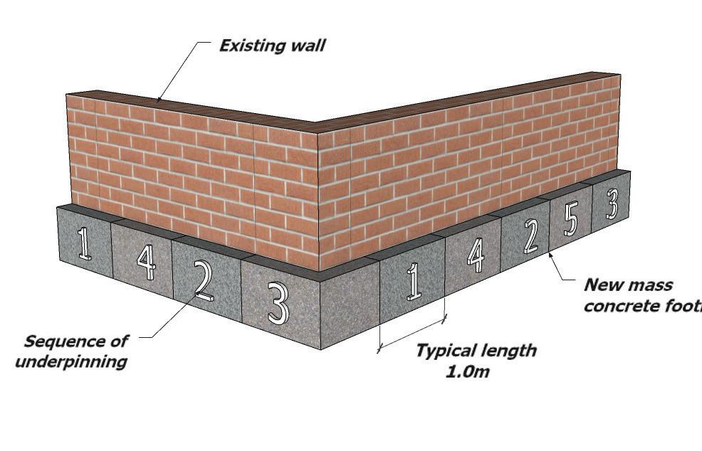
275
17.2
Angle Pile
The stabilization of an existing wall foundation using pairs of piles installed at an angle, through drilled holes in the existing foundation.
Pile and Beam
The stabilization of an existing wall foundation by the installation of Mini Piles in pairs, one as a tension pile, one as a compression pile, connected by a reinforced concrete or concrete encased steel needle beam supporting the wall.
Pier and Beam
The stabilization of an existing wall foundation by the installation of a series of Piers connected to the existing wall by reinforced concrete tee beam and connected with a longitudinal ground beam to provide lateral restraint.
Tanking – Basement Space
If the building has an existing basement or it is proposed to build a new basement it is important that ICW are consulted at the design stage to discuss and agree the proposals. The designer should identify the intended use of the basement as this has a bearing on its design and construction.
Reference should be made to the earlier chapter on Basements.
Damp-Proofing
An insurance backed guarantee to the satisfaction of ICW shall be provided for all injected chemical damp proof courses.
A suitable damp-proof course should be provided to existing walls and be placed at least 150mm above external ground level to ensure that ground moisture does not enter the inside of the building.
A damp proof course should be installed on an existing wall. If not, there are two options available to install a damp proof course retrospectively:
• Injected chemical damp proof courses.
• Physically cutting a new damp proof course.
Injected chemical damp proof courses shall be installed by a registered member of The Property Care Association (who will provide a 10-year underwritten guarantee) and be in accordance with BS 6576 Code of Practise for Installation of Chemical Damp-proof Courses or applicable standards dependant on geographical location.
Most types of wall are suitable for the treatment by a remedial damp-proof course system. There are exceptions to this and include:
• Walls of exceptional thickness i.e. greater that 600mm.
• Rubble filled walls.
• Random flint/granite walls or other similar impermeable materials.
• Mud walls (Cob), wattle and daub.
• Rat trap bond.
Location of Damp-Proof Courses and Membranes
It is essential that any new damp-proof courses are continuous with other damp-proof courses and membranes to provide an effective barrier against rising damp.
Damp-proofing courses should be located in a manner that damp susceptible materials such as suspended timber floors, joist ends, and wall plates are located within a dry zone of the wall construction.
Continuity of injected damp proof courses should be maintained at changes in floor levels, around chimneys and fireplaces, within recesses, alcoves, party walls, garden walls, etc.
Often in rehabilitation work it is not possible to lower ground levels adjacent to walls, as this will reduce the depth or cover to foundation and footings. In cases
276
17.2
where the ground level is higher than the adjacent floor level special attention is required to maintain continuity of the damp proofing system.
Further guidance on damp-proof is available:
• BRE Digest 245 Rising Damp in Walls.
• BRE Good repair Guide 5: Diagnosing the causes of damp.
• The Property Care Association
• Independent third-party certificates acceptable to ICW.
Treatments of Timbers- Rot/Insects
Any remedial treatments shall be carried out by registered members of the The Property Care Association in accordance with their Code of Practice of Remedial Treatment and associated technical leaflets. A 10-year insurance backed guarantee shall also be provided.
In order to obtain insurance, it is necessary to undertake a detailed investigation of all timber members to identify the presence of any insect or fungal decay and treat the affected areas as appropriate. It is essential that the type of fungal attack is correctly identified as treatment methods vary for dry rot and wet rot.
Fungal attack covers wet rot and dry rot. Wood rotting fungi can be divided into two categories according to their effects on the wood:
• Brown Rot- causes the wood to become darker in colour and crack along and across the grain when dry. Badly decayed wood will crumble to dust, and most wet rots and dry rot fall within this group.
• White rot – the wood becomes lighter in colour and the wood cracks along the grain. All white rots are wet rot.
• Insects attack included Common Furniture, Death Watch, House Longhorn and Powder Post Beetle. The root cause of fungal attack is dampness. For
example, dampness may be caused by the following:
• Rain penetration.
• Condensation.
• Hygroscopic salts.
• Defective rainwater goods and roofs.
• Bridging of existing dpcs, or no dpc.
• Defective renders.
• Direct penetration of rainwater through solid walls, particularly those facing prevailing winds.
• Leaking drains and internal plumbing.
• Incorrect external levels.
Fungal attack is controlled by two sets of measures, primary and secondary.
Areas which have not been inspected should be clearly identified to enable a subsequent inspection to be carried out when the structure has been fully exposed; this could include rafter feet and wall plates which are partially prone to rot.
Primary measures consist of locating and eliminating
277
17.2
sources of dampness and promoting the rapid drying out of the structure. Where the timber becomes wet and remains wet e.g. the moisture content exceeds 20%, then it is likely to decay, and by eliminating the source of dampness and drying of timbers below 20%, the fungus will normally stop growing and will eventually die.
Secondary measures consist of determining the full extent of the outbreak then either:
• Removing all decayed timbers.
• Treating of walls to contain fungi within the wall (only applicable to dry rot).
• Treating of sound timbers with preservative where required.
• Using preservative-treated replacement timbers (pre-treated).
• Introducing support measures such as isolating timbers from walls and provision of ventilation between timbers and the walls.
• Appoint a specialist company who can provide automatic building monitoring systems. Timber identified as being at risk of decay (such as lintels, joist ends, flat roof timbers, rafter feet, etc.), can be monitored and any changes in moisture content recorded by a central computer and the appropriate action taken before serious damage occurs.
Floors
Dry rot commonly occurs when timber is in contact with damp brickwork and where ventilation and heating are inadequate. Therefore, particular attention should be paid to cellars, basements and sub-floors and also behind panelling.
Existing Concrete Floors
Where there is an existing concrete ground floor and this is to remain, the following should be identified:
• The thickness and condition of the existing slab, a minimum of 100mm concrete is normally expected. Slabs less than 100mm are more likely to be vulnerable to rising damp, especially if the concrete is of poor quality.
• If there are proposals to increase the load on the existing slab, such as building a masonry wall, the new wall should be built on adequate calculations.
• Are there any gaps between the skirting and floor suggesting settlement of the slab; is the fill beneath the slab over 600mm?
• Are there any cracks in the floor due to settlement?
• If the slab has settled it may be practical to relevel the floor with a new screed or self-levelling compound. Before undertaking any works to a slab which has settled, it must be ascertained that the settlement has stopped.
• Has the slab heaved due to either sulphate attack or clay swelling? Concrete ground floor slabs are vulnerable to attack by water soluble sulphates present in the hardcore, e.g. colliery shale. Where the slab has lifted and is no longer in contact with the hardcore, sulphate attack is the most probable cause. When the slab lifts it causes the walls containing the slab to be pushed out.
Clay heave can be attributed to the swelling of the clay subsoil when there is a recovery of the desiccated zone following the removal of a tree. The amount of heave can be as much as 150mm. This swelling of the clay forces the ground floor slab upwards and can also push out the walls.
Where a slab has heaved, further investigation is necessary to determine the reason for this and appropriate measured taken to rectify the cause and damage. Guidance on this subject matter is available in BRE Good Building Guide 28 domestic floors.
278
17.2
Existing Suspended Timber Floors
Where it is proposed to keep the existing ground floor, the following guidance should be followed:
• The existing floorboards/finish should be lifted to ascertain the condition of the timber joists, wall plates and report carried out by a specialist relating to the insect infestation and fungal attack.
When deciding if an existing ground floor is adequate, there are several areas which should be addressed, these include:
• An adequate DPC to walls/sleeper walls.
• Are all timbers free from rot and insect infestation? Particular attention should be given to the ends of the joists and wall plates.
• Adequate ventilation to the subfloor, (1500mm2 of free opening in air bricks per metre run of wall, in older properties where there is no oversite (subfloor) this figure should be doubled).
• Adequate foundations supporting sleep walls.
• Joists are of sufficient size and span.
• Are any load-bearing internal walls build off floor joists.
• Have joists been weakened by excessive notching or drilling.
• Adequate trimming to hearth.
• Strutting of joists with spans in excess of 2.5m.
The surface of the oversite covering should be above the highest level of adjoining ground or laid to fall with a drainage outlet above the lowest level of the adjoining ground and the outlet screened against rodent entry.
All sub-floors voids should be cleared of all timber/ builder’s rubble as this can provide a ready source of food for dry rot and insects.
Timber joists which were previously built into walls and the joist ends have decayed can be isolated from the damp walls by cutting back the joist and supporting on joist hangers. If the decay extends
beyond the proposed cuts for the joist hangers, then the timber can be replaced. This repair method is should only be used where not more than three joists are affected per floor zone and the joist depth being not less than 140mm, unless designed by an Expert.
There are also proprietary methods of splicing new timbers to existing joists with galvanised plates; these systems are an acceptable method of repairing rotten or damaged joists.
Radon and Contamination
The aim is to improve the resistance to contaminants and moisture as much as possible, but it has been recognised that this is not always practical.
In arriving at an appropriate balance between historic building conservation and improving resistance to contaminations and moisture the advice of the local planning authority’s conservation officer should be sought at an early stage in the design process.
New Concrete Floors
Replacement ground floor slabs should:
• Be minimum 100mm thick and preferably located 150mm above the adjacent ground levels.
• Incorporate below the screed and lapped to form and integral barrier with the adjacent wall dpc.
• Be laid on a minimum 100mm consolidated and well graded non-organic hardcore. Hardcore which is used must be free from water-soluble sulphates and other deleterious materials. Outbreaks of dry rot have been recorded and attributed to hardcore containing pieces of wood infected with dry rot.
In cases where the finished slab level is substantially higher than the damp-proof course level in the wall, special attention is needed to ensure that damp does not bridge over the dpc.
279
17.2
17.3 SUPERSTRUCTURE
Drainage
Where it is intended to use the existing below ground foul drainage system a CCTV survey should be carried out to ascertain the condition of the drains and manholes. The survey should cover size, type of drain, falls and its adequacy to take the proposed discharge. An air or water test could also be carried out.
The use of existing surface water drainage may be acceptable providing that it can be shown to be carrying the water away from the building i.e. to a soakaway located 5m away, public sewer etc. A CCTV survey should be carried out.
Drainage and Ground Services
Excavations for new drains and below ground services should not extend below the spread load line of foundations unless special precautions are taken such as protecting the drains/service installations from damage by backfilling trenches with concrete whilst maintaining flexibility of the drainage system to accommodate movement.
Often with rehabilitation work it is necessary to extend the drainage system to connect to additional sanitary accommodation. Slab levels and drain inverts are fixed and consequently insufficient cover may be provided to the extended drain. The manufacturer’s recommendations for protection
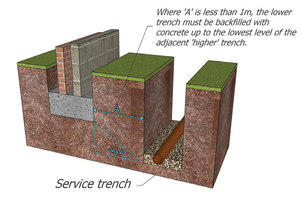
280
17.3
General
Prior to undertaking structural repairs, it is essential that the root cause of the structural defect has been remedied e.g. by underpinning, addition of adequate lateral restraint, buttressing, etc. strengthening works to the structure may also be necessary to accommodate increased or modified loads.
Masonry Walls
When damage has occurred to walls, the cause needs to be investigated.
Likely reasons for the damage include:
• Ground movement – foundation failure, settlement, subsidence, chemical attack..
• Thermal Movement – thermal expansion of wall due to temperature changes.
• Roof Spread – pitched roofs not properly tied, spreading at eaves.
• External and internal walls not bonded together.
• Wall tie corrosion.
• Lintels inadequate over openings.
• Sulphate attack – water soluble sulphates attack cement-based mortar, normally in a wet environment, i.e. below ground level and parapet walls.
• Frost attack.
• Bonding timbers present and subject to rot and shrinkage.
• Ineffective or no lateral support at floor and roof level.
• Moisture ingress.
Cracking in Masonry Walls
Minor cracking can be defined as cracking which occurs in the mortar joints and which does not extend through the masonry components. Providing that the crack is not wider than 4mm and there has been no lateral displacement of the wall, the wall can be repointed. Minor cracking does not usually affect the structural integrity of the wall and may be remedied by raking out mortar joints of the wall and may be remedied by raking out mortar joints to a minimum depth of 15mm and repoint with a mix 1:2:9 Cement : Lime : Sand. If the existing mortar is very weak use a 1:3:12 mix.
Major cracking affects the structural integrity of the wall and investigation should be undertaken to find the cause of the problem. If it is necessary, cut out the brickwork either side of the crack (minimum 225mm) and replace, ensuring that adequate bonding is maintained between new and existing brickwork. It is recommended that brickwork reinforcement is used within the new mortar joints.
Avoid strong mortar mixes and use well graded sand to minimise shrinkage. The use of gun-applied mortar pointing system should be considered, as they are able to match strength and colour of the existing wall.
Where repointing a wall or building a new wall, jointing should be ‘bucket handle’ or ‘weathered’ in preference to flush jointing. Recessed pointing is not acceptable (See diagram overleaf).
281
17.3

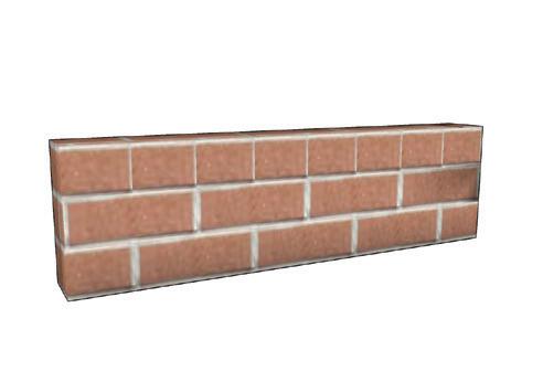
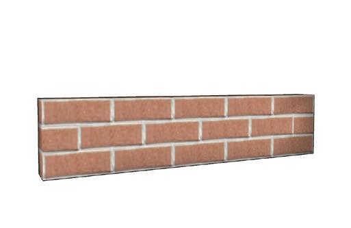
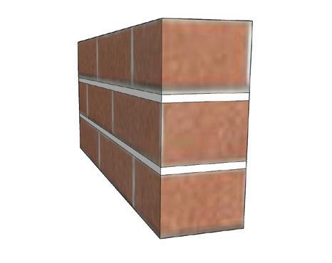
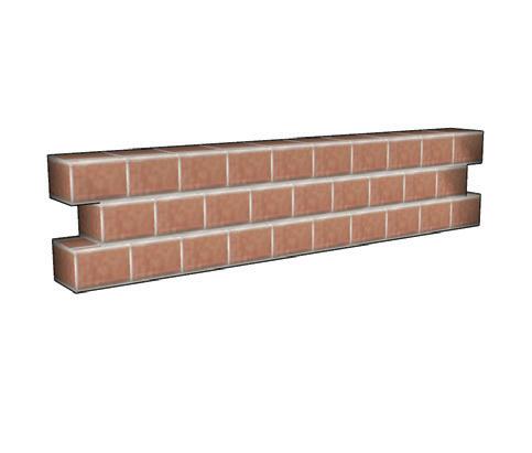
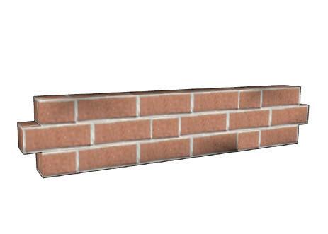
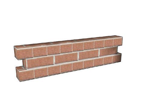
282
Handle (Preferred) Weathered (Preferred) Flush Pointed
cavity walls
sheltered sites) Flush Pointed Header
Bucket
Recessed (on for
on
Bond
Flemish Bond
Flemish Garden Wall Bond English Bond
17.3
English Garden Wall Bond
Walls Out of Plumb/Bulging
Where walls are more than 25mm out of plumb or bulge more than 10mm within a storey height a structural engineer should comment on the stability. The wall may need to be rebuilt or strengthening works undertaken. Where it is intended to provide buttressing walls to support off plumb and/or bulging walls, they should be designed by an engineer. In raised tie roofs (where no ceiling ties are provided at eaves level) lateral spread of the brickwork just below eaves level may have occurred because the roof has deflected. In such cases it is necessary to prop the roof and to rebuild the affected part of the wall.
Lateral Support at Floor and Roof Level
Buildings may show signs of insufficient lateral support through bulging of walls. Many older houses are built with the floors spanning between the front and back walls with a load bearing spine wall and there is no lateral support to the flank walls floor or roof level.
To overcome this, metal rods running through the building at floor and roof level, pulling together with end restraint nuts, can be fitted. This method is still acceptable, but due to the disruption involved as the tie will have to pass through every joist, it is more practical to apply the following system.
Other methods of achieving the acquired lateral supports are available and these include self-tapping tie bars, this system is suitable for tying the walls to floor joists only.
Lateral Restraint at Roof Level
The solution is to use retro-straps system, fitting solid noggins between the first three rafters and mechanically or resin bonding the strap to the wall and screwing it to the noggins. Further guidance is available within the BRE Good Building Guide 29: connecting walls to floors.
Bonding Timbers
These are common on Georgian buildings and were laid in the internal skin of the wall to reinforce it and to provide fixings for panelling, etc. With the low compressive strength of lime mortar and general timber decay, the bond timber compresses under load. As the timber is on the inner skin, the compression causes bulging outwards. This may be apparent on the external face. Normally bond timbers should be exposed during the conversion and removed in short lengths and replaced with bonded masonry.
External and Internal Walls Not Bonded Together
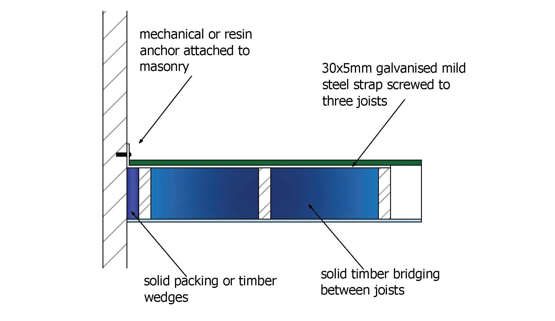
A common defect in properties up to the 1920s is the lack of bonding/tie of party walls to the external wall.
283
17.3
Arches and Lintels
Where existing timber lintels support structural walls and it can be shown that the lintel is adequate for its purpose, i.e. there is no sign of any structural movement, loads will not be increased and the timbers are free from rot and insect infestation, this lintel can be retained. In order to ensure that a lintel is free from rot, a percentage of all lintels should be exposed at both ends and on the outer face for openings in external walls. ICW should be consulted to determine a suitable percentage of lintels to be exposed. Where movement has occurred and the timber lintel is inadequate, the lintel should be replaced with either a concrete or steel lintel and have the appropriate bearing. Consideration may be given to replacing timber with timber and calculations should be provided to justify this.
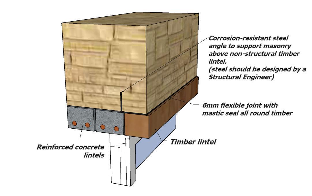
One solution to this, is where new timber lintels are provided over openings, additional structural support can be provided by a concealed steel angle so that the timber lintels acts as a non- structural element.
Where cracking has occurred in masonry arches (openings not supported by a lintel), then it will be necessary to prop the wall and rebuild the arched construction. In cases where failure has occurred due to the low pitch of the arch, it may be necessary to incorporate a lintel.
Wall Tie Corrosion
Cavity walls have been constructed since 1850, but it was not until 1920 that this form of construction was widely adopted. It is important when undertaking a conversion to confirm the construction of the external wall. Care should be taken, where headers are incorporated into the bond of the external brickwork, you should investigate the construction, as many properties in the Victorian period were built with either a 215mm outer leaf and cavity behind, or a 215mm inner leaf, cavity and half brick outer leaf with snapped headers.
Where the wall is of cavity form, a survey of the wall ties on a percentage of the development should be carried out. An initial survey can involve cutting out bricks to inspect the condition and predicted (remaining) life span of the ties. During opening up works the ties can be inspected for their suitability and acceptance by ICW.
Initial evidence of cavity wall failure can include cracking of bed joints in mortar. This is due to the expansion of the wall tie as it corrodes. Bulging of the external leaf could indicate that the ties have failed.
Where there is wall tie corrosion or inadequate ties, a specialist company should be employed to provide a report which includes measures to overcome these defects.
Where wall ties have corroded to an extent that it is serious enough to threaten the stability of the wall or building, a structural engineer should be appointed to determine the necessary remedial works.
New Masonry
Masonry walls should be built off a suitable foundation, incorporate a dpc and be in accordance with Approved Document A (E&W) and Regulation 11 (Scotland), or aplicable standard dependant on geographical location up to three storeys. When a wall is outside the scope of these documents, a qualified Structural Engineer should design the element.
284
17.3
Existing Masonry
Where a wall is adequately founded or supported on a beam which shows no signs of distress, it can remain providing there is no increase in load onto the wall. Any increase in load should be justified by calculation.
However, masonry supported on timber beams should be avoided.
In older properties it is possible that Flitch beams and Bressumers may support masonry walls and these should be examined by an appropriate Expert to ascertain its capabilities to carry the load onto the wall. Any increase in load should be justified by calculation.
Existing solid brick or stone walls may be acceptable as a weather resisting wall subject to the exposure category of the building (see exposure to wind driven rain map page 119 and the porosity of the masonry. It is anticipated that all buildings located in severe or very severe locations will require a specialist’s report to identify the extent of any necessary remedial treatment.
The specialist report including the proposed design and/or the manufacturer’s details must be forwarded to ICW for approval along with the other requested reports that form part of the conditions placed on the warranty.
If the above situations cannot be satisfied, then a new external cladding or render system will need to be installed.
Independent Metal or Timber Framed Systems
These should not be fixed to the existing masonry walls but fixed at the “head and base” to avoid direct contact. Ventilation should be provided to avoid build-up of condensation between the masonry and the inner lining system.
Impervious Sheet and Drained Sheet Systems
Systems to prevent water penetration should be installed in accordance with the manufacturer’s recommendations and shall possess third party accreditation acceptable to ICW.
New Studwork
Studwork should be in accordance with current Building Regulations at the specific time of construction.
Existing Studwork
Many properties before 1880, have trussed internal partitions, usually located approximately halfway back in the depth of the property. Often these walls are load bearing and continue up through the building and carry floor and roof loads on the foundations.
If a timber partition is load bearing, provided it is adequate and the loads are not being increased and the timber is free from rot and insect infestation, the partition can remain. Where there are defects i.e. the floor sags on the line of the partitions and there is distortion of door heads then additional strengthening works should be undertaken.
New door openings cut into an existing trussed partition should be overseen by a qualified structural engineer, as it can adversely affect the triangulation of the truss.
285
17.3
Timber Floors above Ground Level
Existing timber floor joists can be retained within the building providing that they are adequate for their purpose. The following points should be considered:
• Joists are of sufficient size for the span.
• Load on the floor is not being increased.
• Have joists been weakened by excessive notching and/or drilling.
• Ends of joists free from rot.
• All timbers to be treated for insect infestation and wood rot.
• No masonry walls are built off timber joists.
• Adequate trimming to hearth.
• Solid strutting or herringbone.
Where the existing joists do not comply with the span tables on page 287, but can be shown that the joists are adequate, in that there has been no floor deflection, ICW will consider these to be acceptable.
Timber Floors
A common defect in floor joists is that the ends which are built into solid external walls have often rotted. A percentage of all existing joists should be examined to ascertain if there is any rot in timbers. Where timber rot is identified in these joists, then further investigation should be undertaken on a further percentage of the joists.
A system of dealing with the rotten joists should then be implemented:
• Before carrying out this type of work, you should consult a qualified structural engineer to ensure the structural integrity of the building is not compromised.
• Proprietary methods of splicing new timbers to existing joists with galvanised plates is also an acceptable method of repair.
• Where the joists have been previously excessively notched to accommodate services then they should be strengthened by the addition of steel plates securely connected to joists.
Movement Joists between New and Existing Construction
In order to avoid the damage resulting from differential movement between new and existing work, it is necessary to isolate the new extension from the existing construction whilst at the same time maintaining lateral support to the new construction and ensuring a weather tight joint, the isolation joint should extend through the foundations.
Walls of Special Construction
If it is intended to retain walls of special construction such as wattle and daub, tudor, mud walls (cob) etc, they should be altered so as to form a non-structural element e.g. by the incorporation of an additional load bearing wall or framing which provides lateral support to the wall and supports all structural loads previously supported by the wall. It is also necessary to ensure that the wall provides an adequate barrier to the passage of rainwater into the fabric or the inside of the building. This may be achieved by e.g. the formation of cavity construction whereby the special wall forms the external leaf and the cavity construction provides the required resistance to rainwater penetration. It is recommended that expert advice is obtained for these types of construction.
Alternations to Existing Openings
Where existing openings are to be filled with masonry, the new work should be adequately bonded to the existing; the weather resistance of the wall maintained and, if a party wall, comply with the requirements for sounds installation.
Often it is necessary to make minor modifications to existing openings in order to accommodate new frames. In such cases the length of bearing of the supporting lintels should be verified and where less than 150mm the lintel may have to be replaced.
286
17.3
clear span between supports with imposed loads of 1.5kN/m2. Dead load more than 0.25 but not more than
Key:
1. C24 timber is approximately equivalent to SC4 grade timber.
2. Non loadbearing lightweight partitions (loading not greater than 0.8kN/m2 run)
Notes:
Joists should be doubled up beneath baths and any other pointof concentrated load. Maximum partition load 0.8kN/m2 (eg timber framed stud partition). Non loadbearing partitions should be supported as shown in diagram 2.107 No notches in trimmer beam unless designed by an Expert.
287 Floor Joists Permissible
0.50kN/m2 Sizes with No Partitions Sizes with l/w3 Partitions Size of Joist mm x mm Spacing of Joists (mm) Size of Joist mm x mm Spacing of Joists (mm) C242 C242 400 450 600 400 450 600 400 400 600 400 450 600 Maximum Clear Span of Floor Joist (m) Maximum Clear Span of Floor Joist (m) 47 x 72 1.27 1.15 0.89 1.35 1.27 1.10 47 x 72 1.15 1.04 0.80 1.21 1.14 0.99 47 x 97 1.92 1.82 1.46 1.03 1.92 1.68 47 x 97 1.73 1.64 1.31 1.82 1.73 1.51 47 x 122 2.55 2.45 2.09 2.65 2.55 2.29 47 x 122 2.29 2.21 1.88 2.39 2.29 2.06 47 x 147 3.06 2.95 2.61 3.18 3.06 2.78 47 x 147 2.76 2.65 2.35 2.87 2.76 2.50 47 x 170 3.53 3.40 2.99 3.67 3.54 3.21 47 x 170 3.18 3.06 2.69 3.31 3.18 2.89 47 x 195 4.04 3.89 3.39 4.20 4.05 3.68 47 x 195 3.64 3.50 3.05 3.78 3.64 3.31 47 x 220 4.55 4.35 3.79 4.71 4.55 4.14 47 x 220 4.09 3.92 3.41 4.24 4.10 3.73 63 x 97 2.19 2.08 1.82 2.31 2.19 1.93 63 x 97 1.97 1.87 1.64 2.08 1.97 1.73 63 x 122 2.81 2.70 2.45 2.92 2.81 2.55 63 x 122 2.53 2.43 2.21 2.63 2.53 2.30 63 x 147 3.37 3.24 2.95 3.50 3.37 3.07 63 x 147 3.03 2.92 2.66 3.15 3.04 2.76 63 x 170 3.89 3.74 3.40 4.04 3.89 3.54 63 x 170 3.50 3.37 3.06 3.63 3.50 3.19 63 x 195 4.44 4.28 3.90 4.61 4.45 4.05 63 x 195 4.00 3.85 3.51 4.15 4.00 3.65 63 x 220 4.91 4.77 4.36 5.05 4.91 4.56 63 x 220 4.42 4.29 3.93 4.54 4.42 4.10
17.3
Chimney Removal
Imperial Brickwork – Metric Blockwork
Where it is intended to use this construction, attention should be made to ensure that the wall ties do not slope inwards towards the inner leaf. Conventional coursings 450mm centres vertically will not match as imperial bricks are bigger than metric. The use of proprietary ties should be considered.
Chimneys
When removing chimney stacks, they should be taken down to below roof level and capped. Chimneys located on external walls should be ventilated to the external air at roof and base level.
Where it is intended to re-use existing flues they should be tested for airtightness.
Adequate support should be provided to chimneys after removal of chimney breasts.
Cantilever slabs built into existing walls or corbelling should not be used.
The design of any support should be justified by calculation.
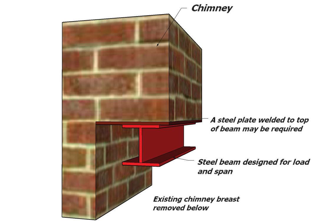
When intending to retain existing chimneys: the adequacy of the masonry, the existing trays and flashings to resist moisture and retain structural stability should be confirmed by the Expert’s report.
Sounds Insulation
The aim is to improve the sound insulation as much as possible it has been recognised that this is not always practical. Depending on the status of the building various alternatives are permitted. Please refer to Building Regulations Approved Document E or applicable standard dependant on geographical location.
Concrete/Steel Framed Structures
Where the scheme involves converting a concrete or steel framed building into dwellings the following guidance is given.
An appraisal of the existing building should be carried out by a qualified Structural Engineer considering the proposals for the change of use, this will include:
• Condition of the structural frame including joints.
• Proposal to increase loadings on the structure and foundations.
• Alterations to existing load paths.
• Alterations to stability systems.
• Changes in environmental exposure.
• Recommendations to cover additional reports, testing by specialists.
The floor loads on the building may decrease as they will now be for domestic use only, were previously they were for example, offices. ICW will accept a statement from a qualified Structural Engineer confirming, where appropriate, that the existing foundation design is acceptable for the new loads subject to the building showing no signs of distress i.e. movement, cracking etc.
Where the intention is to increase the load on the existing structure e.g. by the introduction of an additional floor, then structural calculations should be provided to prove the adequacy of the building and foundations.
288
17.3
Concrete Framed Buildings
Where the building is of concrete construction additional reports are needed for:
• Carbonation
• Chlorination
The two major causes of corrosion in concrete are carbonation in association with inadequate depth of cover to reinforcement and chlorine penetration due to de-icing salts and admixtures used to accelerate the setting and hardening of concrete in temperatures at or below freezing point.
Carbonation involves a reaction of carbon dioxide in the air with the free lime present in the concrete. Over a period, this reduces the pH level of the concrete. With a reduction in the alkalinity, and the presence of both water and oxygen, corrosion of the embedded steel will occur.
Visual surveys on concrete structures are a starting point to gather information. However, care should be taken as the concrete structure may not show any obvious signs of corrosion and yet corrosion of the reinforcement may be occurring. It is important that a second stage survey incorporates the following:
• Chemical tests on the concrete structure to ascertain if corrosion of the steelwork is or is likely to occur.
• Depth of carbonation can be assessed either on site or in the laboratory and the depth of the reinforcement measured. This allows those areas of risk to be identified.
• Chloride ion content can be taken by analysis of a drilled dust sample from the concrete.
Where concrete repairs are necessary, they should be carried out by a specialist contractor.
High Alumina Cement Concrete (HACC)
Where High Alumina Cement Concrete has been used in a building and the intentions are to keep the existing structure ICW may consider the property for warranty subject to:
• The structure being free from obvious signs of deterioration.
• The building being weather-tight.
• Structural calculations being provided to show that the floors and roof can solely carry the loads imposed on them.
• Typically HACC precast concrete beams were cast as “X” or “I” shaped beams.
Steel Framed Buildings
In addition to any structural reports a visual inspection of the steel frame should be carried out to assess the extent of any corrosion of the framework.
Where corrosion is present accurate measurements can be made using an ultrasonic gauge. Data collected can then compare the thickness of steel sections against the original steelwork drawings, British Standards and Historical Structural Steelwork Handbook to ascertain if the structural frame is adequate for the proposed loads.
Steel Frames
When corrosion is apparent, what appears is a thick layer of rust e.g. 10mm only actually indicates a loss of between 1.9mm and 1.6mm of steel and it is therefore important to take readings.
Exterior Steelwork - should be inspected. Where corrosion is visible, the steel can be grit blasted cleaned and recoated.
Perimeter Steelwork- in direct contact with the outer leaf of the building can be prone to corrosion particularly in older properties. A sign indicating that this has happened is the displacement of the external masonry due to the expansion of the steelwork caused by corrosion. Corroded steelwork occupies between 6 and 10 times the volume of the original material.
289
17.3
Perimeter steelwork - can normally be inspected during the conversion process and the appropriate repairs/replacement carried out.
Interior Steelwork - normally corrosion of unprotected steelwork within the interior of a building is low with only superficial rusting.
Providing a visual inspection confirms this and the environment intends to remain dry no further treatment of the steel will be required. Where the proposals involve the steelwork in a “wet” environment such as kitchens and bathrooms it should be adequately protected.
Concrete/Steel Frames
When corrosion is apparent, what appears is a thick layer of rust e.g. 10mm only actually indicates a loss of between 1.9mm and 1.6mm of steel and it is therefore important to take readings.
Exterior Steelwork - should be inspected. Where corrosion is visible, the steel can be grit blasted cleaned and recoated.
Perimeter Steelwork- in direct contact with the outer leaf of the building can be prone to corrosion particularly in older properties. A sign indicating that this has happened is the displacement of the external masonry due to the expansion of the steelwork caused by corrosion. Corroded steelwork occupies between 6 and 10 times the original volume of steel the steel.
Perimeter steelwork - can normally be inspected during the conversion process and the appropriate repairs/replacement carried out.
Interior Steelwork - normally corrosion of unprotected steelwork within the interior of a building is low with only superficial rusting.
Providing a visual inspection confirms this and the environment intends to remain dry no further treatment of the steel will be required. Where the proposals involve the steelwork in a “wet” environment such as kitchens and bathrooms it should be adequately protected.
Bimetallic Corrosion
This should be considered in the existing and proposed structure. Bimetallic corrosion occurs where two different metals are in electrical contact and are also bridged by water or water containing other chemicals to form an electrolyte, an electrical current pass through the solution from the base metal to the noble metal. Consequently, the noble metal remains protected and the base metal suffers increased corrosion.
Where there is a possibility of this occurring or if it has already occurred advice should be taken from a specialist on how to deal with it.
Cast Iron, Wrought Iron and Mild Steel Structures
Many older buildings which are converted into dwellings e.g. warehouses, cotton, mills etc were built using cast iron, wrought iron or mild steel. Cast and wrought iron were first introduced in 1800’s followed by the use of steel around 1890. With the onset of steel, the use of cast and wrought iron declined.
When the intention is to keep the existing structural elements, an appraisal of the existing building is necessary. In addition to this the engineer should comment on the following:
• Determine age of the building and materials used.
• Assess how its constructed has faired.
• Justify the loadings by calculation.
• Identify areas where additional testing and/or opening is necessary.
If the proposed loads remain unchanged or reduced, as will probably be the case, and it can be shown that the existing structure had not suffered any deterioration due to corrosion, deflection of structural members etc; the building may only require localised structural alternations. When the intention is to increase loads, carry out major structural alterations, or the existing building is under designed, a structural engineer should comment on this and provide calculations to justify the proposals.
290
17.3
Filler Joist Floors
Many buildings of late Victorian and Edwardian period were built with floors constructed of clinker concrete supported by embedded iron or steel joists. The concrete produced with clinker aggregate was porous and therefore provided poor corrosion protection to the metal.
The clinker also contains particles of unburnt or partially burnt coke or coal which contains substantial proportions of sulphur. As the concrete is porous the sulphur oxidises to form sulphur dioxide (SO2) and if moisture is present this then forms sulphuric acid (H2SO4). Where floors have been subject to the weather for any length of time severe corrosion of the embedded iron or steelwork is likely to have occurred.
When considering a conversion in a building which has filler joist floors it is important to firstly investigate to ascertain if the floors have been subject to damp conditions and whether any significate corrosions has taken place.
PRC Repairs
Particular attention should also be made during the conversion to ensure that the floor remains dry and this could include providing a temporary covering if removal of the existing roof is necessary.
ICW will need to inspect the property prior to work commencing to comment on those elements which are being retained:
• Ground floor slab – any signs of movement or damp.
• First floor joists – deflection of structural timbers, rot, adequate ventilation, insulation.
• Drainage- external below ground drainage.
• External – paths, drives, garden walls.
• Services – gas, electricity, water etc. Where any obvious defects are apparent in the retained structure they should be replaced or repaired.
PRC Demolition and Rebuild
Where the PRC property is demolished to slab level ICW will consider the rebuild for warranty purposes subject to:
• A structural engineer should comment on the adequacy of the existing foundations to take the proposed loads. Where it is necessary, the footing should be underpinned or a new foundation ‘stitched’ to the existing.
• The existing slab should be examined for any signs of settlement, heave or sulphate attach and where appropriate trial holes cut into the slab to ascertain the thickness of concrete and the type of hardcore.
• Any new load-bearing walls are to be built on foundations unless it can be justified by calculations that the existing slab can carry the load.
• Where the existing below ground foul drainage system is retained a CCTV survey should be carried out.
Surveying Roof Timbers
All roof timbers should be surveyed by a specialist and any necessary treatment carried out. Particular attention should be given to rafter feet, wall plates and valley timbers as these often show signs of rot.
Roof Structure
It is essential that the roof structure has adequate strength, stiffness and dimensional accuracy appropriate for the new roof covering. In many existing buildings the roof structure is inadequate to support roof loads and has suffered from excessive deflection. Often, the necessary remedial works are relatively simple and inexpensive. Common problems encountered include:
• Excessive spans of rafters, purlins, binder and ceiling joists.
• Inadequate ties between rafters and ceiling ties.
• Insufficient number of collar ties at purlin level.
291
17.3
• Decay of rafter feet and valley beams.
• Settlement of purlin supports.
• Lateral spread of raised-tie roofs.
There are several solutions for strengthening roofs which include:
• Provision of diagonal struts supported on loadbearing walls to reduce effective spans of purlins.
• Provision of additional purlins.
• Inclusion of new binders and collars.
• Strengthening of rafters at ceiling level in raised tie ceilings.
• Additional ties to connect rafter feet to ceiling joists.
• Splicing new timbers to rafter feet.
All strengthening work should be designed by an engineer.
Additional supports are often required for a new water tanks in roof spaces. These should be located such that ceiling joists are not excessively loaded and the loads imposed are transmitted directly to supports.
Roof Coverings
Systematic replacement of all roof coverings, including associated support systems such as battens, felt, flat roof decking, fascia’s, soffits and flashings should be carried out, unless it can be shown that the existing roof covering is adequate. The existing roof covering will only be considered as adequate if it has been replaced in the last 15 years and must be subject to an Experts report. All roof coverings older than this should be replaced. Consideration of reusing slates/tiles will be given subject to the condition of them and we may request that these be tested by a specialist organisation. Fixing of slates, tiles, the condition of existing fixings e.g. nails and clips should be examined if the intention is to keep the roof covering.
Where the existing construction is close boarded and there are no provisions to strip the roof to felt and batten ICW will consider close boarding to be acceptable if:
• Subject to survey by an expert which must also consider the exposure level.
• There are no signs of damp ingress into the roof void due to wind driven rain, snow or capillary action of moisture.
A specialist report will be required to confirm the adequacy of the existing roof coverings and if timber treatment is required. If the proposals are to replace the existing roof coverings, then a temporary roof must be erected to protect the building and prevent water ingress into it. Failure to do so can lead to the building becoming saturated and the risk of wet/dry rot occurring.
Please note that if you do not provide a temporary covering, ICW may refuse to provide policy cover for the project. Adequate ventilation should be provided.
Where it is intended to re-use existing roofing tiles or slates, they should have a life span of at least 15 years. Where replacement coverings are heavier than the existing coverings, the works are usually controlled under the Building Regulation and approval is required in respect of the strengthening works to the roof structure.
In the case of replacement roof coverings where no extra load is incurred it may still be necessary to strengthen the roof structure if the roof has deflected.
292
17.3
Weather Resistance of Walls and Cladding
Existing solid brick or stone walls may be acceptable as a weather resisting wall subject to the exposure category of the building (see exposure to wind driven rain map page 119 and the porosity of the masonry. It is anticipated that all buildings located in severe or very severe locations will require at least one of the additional treatments noted below. However, all solid masonry wall situations will require a specialist’s report to identify the extent of any necessary remedial treatment.
The specialist report including the proposed design and/or the manufacturer’s details must be forwarded to ICW for approval along with other requested reports that form part of the conditions placed on the warranty.
External Treatments
Existing cladding can be retained if it can be shown that:
• The system is maintaining the integrity of the building.
• It is adequately fixed and the expected life span of the fixings where appropriate is in excess of 15 years.
• The cladding material is free from and defects.
• Adequate provision for movement has been allowed.
If the above situations cannot be satisfied, then a new external cladding or rendering system will need to be installed.
Internal Treatments
An alternative to preventing moisture penetration by using externally applied claddings and renders is internally applied methods.
Systems are available that are installed on the inside of existing walls to prevent moisture penetration reaching the internal accommodation. These include: Independent metal or timber framed systems.
• These should not be fixed to the existing
masonry walls but fixed at the ‘head and base’ to avoid direct contact. Ventilation should be provided to avoid build-up of condensation between the masonry and the inner lining system.
• Impervious sheet and drained sheet systems. Systems to prevent water penetration should be installed in accordance with the manufacturer’s recommendations and shall possess third party accreditation acceptable to ICW.
Interstitial Condensation
Vapour control layers may need to be incorporated on the warm side of the thermal insulation. Voids and cavities may also need to be ventilated.
Surface Condensation
Under certain conditions the warmth from sunlight falling onto damp solid masonry wall can drive moisture inwards and form condensation on the outside of a vapour barrier.
Control of Damp Penetration
Measures should be taken to ensure that thermal insulation in cavities does not encourage the passage of damp from the ground or from the exterior of the building to the inside of the building.
293
17.3
Thermal Insulation of Walls and Claddings
Various methods exist to upgrade the thermal insulation of existing walls and floors. Regardless of the methods adopted, it is essential that risks associated with increased thermal insulation are minimised, including:
• Surface condensation caused by improvements to draught proofing of the building.
• Interstitial condensation caused by moisture laden air passing from a dwelling to within the fabric of the structure and condensing on cooler surfaces.
• Increased risk of damp penetration caused by filling of cavities with insulation.
• Maintaining the robustness of the external and internal wall surfaces by the provision of adequate mechanical protection over insulation materials. e.g. externally applied insulation systems with render coat mechanical protection
• Avoidance of cold bridges around openings and when structural elements extend through thickness of the building envelope.
• Where planning restrictions prevent the thermal upgrade of the building then ICW may deem it appropriate to add an endorsement to the policy regarding the risk of condensation.
Rendering for Conversion/Refurbishment
Where the condition and bond of the existing render can be shown to be adequate it can remain subject to the following exceptions:
• If the render bridges the dpc.
• Above door and window openings where it is necessary to examine the type and condition of the lintels.
• Where there are signs of structural movement in the building and further investigation is required.
• Guidance on this subject is available: BRE Good Building Guide 23 & 24.
• Assessing external rendering for replacement or repair.
• Repairing external rendering.
• Please refer to previous section on rendering.
294
17.3
Where the condition and bond of the existing plaster can be shown to be adequate, it can remain with exception of the following:
The existing plaster should be removed where:
• Where rising damp is present.
• Where a chemical damp-proof course is installed.
• At the junction of external walls and part walls to see if they are properly bonded.
• Above openings to examine the makeup and condition of lintels.
• Where there is possibility of bond timbers which may have decayed.
Where a chemically injected damp-proof course is installed it is necessary to remove the plaster one meter above the dpc level or 600mm above any apparent salt line/dampness whichever is the higher.
Re-plastering work should be delayed as long as possible in order to encourage rapid evaporation of residual moisture and the building should be well ventilated during the drying period.
Plastering work must comply with independent thirdparty certificates acceptable to ICW and the chemical damp-proof course manufacturers’ recommendations. Recommended plasters usually incorporate adhesives to increase resistance to the passage of hygroscopic salts from the wall into the plaster. They should not, however, act as a vapour barrier.
Gypsum plaster should not be used in conjunction with chemically injected damp proof courses. The plaster should not bridge the damp-proof course or be in contact with the ground floor slab. Final redecoration should not be carried out until residual moisture has disappeared. Matt emulsion paint is recommended for the use during this period. Internally drilled holes which are concealed by skirting boards etc. should not be plugged. Other visible holes and external holes should be plugged.
295
17.3
296
297 18.0
FINISHES & TOLERANCES
INTRODUCTION
Finishes can be open to interpretation and often be very subjective. Terms often used are “Aesthetically Pleasing” which generally refers to an object or item that someone considers to be beautiful or attractive and that their needs are fulfilled. Other terms used can include amongst others “Kind to the eye”; “High Quality”; “Golden Ratio”.
In the Construction Industry, as in other industries, there are standards based on BS 8000-0: 2014 Workmanship on Construction Sites; Introduction and General Principles and Regulation 7: Materials and Workmanship of the Building Regulations 2010, 2013 edition, which covers the current European regulation 305/2011/EU-CPR. These are a series of standards covering workmanship in the execution of certain works on construction sites. Amongst others, it looks at issues such as tolerance, accuracy, fit and preparation of materials.
In order to meet with ICW warranty recommendations certain levels of finish need to be achieved by developers and builders during the construction process and the final finished product.
ICW warranty technical requirements, sets out standards that developers should meet during construction to ensure that the finished properties have the benefit of the applicable ICW Warranty. The standards give guidance on acceptable tolerances that will be applied by ICW in determining whether the standards have been met.
This section will also provide useful guidance on whether items, especially of a cosmetic nature, can be deemed a defect. Guidance on such issues will also be explained and the use of day/artificial light and viewing distances of anything from 0.5 – 3.0m dependent on the particular criteria being inspected.
As an introduction to this section and the most common areas of concern for occupiers are:
Walls and Ceilings, which should be:
• Reasonably uniform, can have minor textural differences around lights and other fittings.
• No visible gaps between fittings and surface, e.g. switch plates. Two or more adjacent sockets, switches etc. should be aligned horizontally.
• Jointing tape should be fully covered and unobtrusive in the finished surface.
• In plastered walls, tooling marks may be visible.
• Some cracking up to 2mm wide can occur at wall, floor and ceiling junctions.
• Cracks may occur in wall finishes which pass across floors, e.g. in staircase walls.
• Where stair strings abut a wall, cracks can appear due to shrinkage of materials.
Floor and wall joints:
• Gaps between floor (without coverings) and skirting should not exceed 5mm.
• Joints in skirting should look continuous.
• Subsequently, gaps may appear between floor finish and skirting, joints and corners and between wall finish due to drying out floors
Fitted furniture (including doors and drawers):
• Be visually aligned and not have conspicuous abrasions furniture (including doors and drawers)
• Be visually aligned and not have conspicuous abrasions or scratches.
Joint sealants should be:
• Gaps between floor (without coverings) and skirting should not exceed 5mm.
• Joints in skirting should look continuous.
• Subsequently, gaps may appear between floor finish and skirting, joints and corners and between wall finish due to drying out. Floors
Painted and varnished surfaces should be:
• Even, free from conspicuous runs and prominent brush marks.
• Timber may show limited grain.
• Drying and shrinkage may cause cracking of paint finish.
• Resin is likely to exude from knots.
298
18.0
MASONRY
The following provide maximum variations as follows:
Viewed on plan:
• 10mm variation in any length of wall up to 5m.
BRICKWORK, STRAIGHTNESS ON PLAN
Straightness on plan


Bed Joints:
• 10mm variation in any length of wall up to 5m.
• pro rata on walls less than 5m.
• 15mm maximum variation on walls over 5m
• There should be no persistent variations in the level of the bed.
• The bed joint should not vary from the average of eight consecutive bed joints by more than 5mm.
299
5m
Wall 25 x 25mm Spacing
Reference line Nominal
of line
10mm deviation 35mm
10mm in any Max deviation 5m wide wall
Figure 1: Brickwork, straightness on plan
Brick
blocks
wall
Max
+/-
Line of bed joint Horizontal reference line +/- 10mm deviation for walls 5m long 5000mm
Figure 2: Level of bed joints
18.0
LEVEL OF BED JOINTS
MASONRY
Perp Joints:
• Vertical alignment of perpend joints should not deviate significantly from the perpendicular.
• Bricks will vary in length. As a result of their manufacturing process, not all perpend joints will align. However, there should not be a collective transposition of the perpend joints in a wall.
Plumbness:
• Maximum variation of 20mm from upright in the overall height of a wall.
• Maximum deviation of 10mm per storey height of around 2.5m
Rendering on walls should be:
• Reasonably consistent in texture, finish and colour.
• Some hairline cracking and crazing is likely to occur in both traditional; sand and cement; lime mortar renders and proprietary render systems. Such cracking and crazing should not impair the performance of the render
• Crazing, which may occur in the render surface, should not be more than 0.2mm wide.
• There may be some colour variation in appearance. This may be due to differences in suction of the background and orientation of the wall.
• Daywork joints, patching and other repairs may be visible but should not be unduly obtrusive.
Tile hanging and cladding:
• Uniform appearance
• Tolerances consistent with manufacturer’s recommendations.
It should be noted external finishes will dull over time depending on several factors such as exposure to sunlight, rain, pollutants and the presence of trees.
Fair faced brickwork and blockwork which is usually found inside plant rooms, storage areas and garages:
• General uniform appearance.
Functional levels ensuring consistent levels of texture, finish and appearance.
300
STOREY HEIGHT Plumb line 50 x 50mm Spacing block
Figure 4: Plumb of wall (storey height)
18.0
PLUMB OF WALL (STOREY HEIGHT)
INTERNAL WALLS AND CEILINGS
For plastered and drylined surfaces there should not be:
• No sharp differences of 4mm or more in any area of 300mm
• Maximum deviation of +/- 5mm in a 2m straight edge for both horizontal or vertical surfaces.


Openings:
• Where it is intended for reveals to be square +/8mm deviation off square in to reveal depths of no more than 200mm
• Head and cill tolerances 6mm up to 1.5m wide; 10mm for over 1.5m wide.
Junctions:
• Small cracks up to 3mm in thickness can be expected to wall, ceiling, floor and service ducts.
• Changes in building materials at junctions 3mm thick cracks are most likely.
Floors
• Maximum of 4mm per metre out of level and a maximum of 25mm over larger spans.
• Natural and therefore expected occurrences caused by shrinkage in the normal drying processes can include:
• Fracturing of screeded floors
• Shrinkage of timber floors and staircases resulting in cracks and squeaking of adjoining materials.
301
Max 10mm deviation in 2m Level of ceiling: Max 10mm out of plumb in a storey height Plumb of wall finish: up to 2.5m - max 20mm out of plumb for a continuous wall height greater than 2.5m Maximum deviation in walls and ceilings 90° 90° 90° 5mm 5mm +/- 8mm in 200mm +/- 8mm in 200mm Service ducts: Max 8mm deviation on internal finish of service ducts Internal corners: Max 15mm deviation using a 500mm square Flatness of wall: Max deviation +/- 5mm from 2m straight edge with equal offsets, horizontally and vertically 5m 5mm 5mm 2m Max +/- 6mm deviation from 2m straight edge with equal offsets Flatness of ceiling: 90°
18.0
JOINERY INCLUDING DOORS AND WINDOWS
Doors and windows, the following are without prejudice to satisfactory performance in terms of weather tightness, draught free and resistance of fire:
• Maximum out of level deviation of 5mm for openings up to 1.5m wide.
• Maximum out of level deviation of 10mm for openings over 1.5m wide.
• Door or window frames should not be distorted in a structural opening.
• Maximum of 10mm out of plumb over the height of the frame


• Maximum distortion of the door 5mm in width and 9mm in height.
• Maximum 5mm gap at head and jambs and between adjoining doors
• Minimum gap to underside of door from finished screed to be 5mm up to a maximum of 22mm dependent on final floor finish.
• Note: where fire doors are being installed manufacturer’s recommendations to be followed.

Scratches on doors, windows and frames, when viewed in daylight and from a minimum distance of 2m should not have:
• Prominent abrasions or scratches
• Surface blemishes caused during the building process should be removed in accordance with manufacturers’ guidance which may include respraying, painting or polishing.
• Where there is no available daylight, scratches can be viewed using fixed wall or ceiling lighting but not portable devises i.e. flashlamps and torches.

These dimensions are without prejudice to satisfactory performance in terms of weather tightness, exclusion of draughts and fire resistance where appropriate Max 10mm out of plumb over height of frame (in one direction only)
Max 5mm gap between door and head of jamb (for fire doors, use manufacturer's recommendations). For double doors, the gap at the meeting styles should be max 5mm Door distortion
Other Joinery Items
• Joints are acceptable in skirtings but when viewed from a minimum distance of 2m appear continuous.
• Fitted furniture with doors and drawers, when viewed from a minimum distance of 0.5m should be:
• Aligned vertically, horizontally and in plan.
• Gaps between adjacent doors and or drawers should be consistent.
• There should be no visible change in level at intersections of adjacent worktops.
302
Reveals: Max out of plumb tolerance from 6mm for openings up to 1.5m high. 10mm for openings more than 1.5m high Window frames up to 1.5m in height - max 6mm out of plumb. Over 1.5m in height max 10mm out of plumb Head and sill: Max out of level tolerance 6mm for openings up to 1.5m wide. 10mm for openings more than 1.5m wide Max 3mm out of level across reveal (measured from frame) Window frame should not be distored in the opening The gap between the underside of an internal door and unfinished floor (concrete, screed, etc) should be min 5mm and max 22mm
Max
across width Max 9mm in height
5mm
Door frame should not be distored in the opening
Max 5mm across width Max 9mm in height Max 6mm deviation Straightness of external reveals Straight edge (1m long)
18.0
Door distortion
Straightness of reveal
The appearance and visual quality of insulated glazing and glass panes is dependent on the optical quality of the glass components inherent due to the manufacturing processes and the visual quality of the glass panes.
Toughened, laminated and special coatings of glass can also affect the optical and visual qualities of glass.
Based on recommendations in BS EN 1279-1, the following criteria should be used when inspecting glass:
• Viewed from a minimum 3m from a glass pane.
• Do not find faults at close range, mark them visible then view from the above distance.
• Looking through the glass at a distant view and not at the glass itself.
• Do not use strong lamps or magnifying glasses.
• Time for inspecting should be no greater than 1 minute per m2
The following is acceptable if not within 25mm of the perimeter of the glazed area and are not bunched or obtrusive:
• Bubbles, blobs and blisters
• Hairlines
• Fine scratches not more than 25mm long
• Minute particles
PAINTED, STAINED AND VARNISHED SURFACES
When viewed from a minimum distance of 2m, surfaces should be:
• Free of nail holes, cracks (not shrinkage cracks) and not be seen.
• Smooth and free from conspicuous runs and prominent brush marks.
• There should be no bare or starved areas.
• Colour, texture and finish should be consistent. However, around such things as electrical switches and light fittings there may some inconsistency.
EXTERNAL WORKS
Drives and paths surfaces and standing water:
• Surface variation should not exceed a difference of 10mm from a 2m straightedge.
• Some fracturing or weathering can be expected in natural products such as stone, granite etc.
• Timber surfaces may show limited raised grain and the colour and texture may also vary.
• Joints are to be filled and decorated.
• There may be some resin release from knots in timber which is a natural occurrence.
• Where painted surfaces are touched-up, minor colour variations will occur.
• The finish should be applied as per the functional requirement and manufacturers’ recommendations.
• Drainage covers in hard landscaping areas should be level with their surroundings to avoid trip hazards.
303
GLAZING
18.0
304
TECHNICAL DEFINITIONS
305
19.0
TECHNICAL DEFINITIONS
Acoustics:
Sound and noise
Aggregate:
Material mixed with Portland cement to form concrete. Fine aggregate is sand, coarse aggregate is gravel.
Air bricks:
Perforated earthenware air vents to provide subfloor or roof void ventilation.
Airflow Rates:
Measurement of a flow of air through a ventilation unit or duct.
Air Changes per Hour (ACH):
Air changes in relation to the volume of a room.
Air leakage:
The rate at which air leaks form a building.
Air Permeability:
The measurement of air leakage (ie (>) 5m /(h.m ) at 50 Pa).
Approved Document:
Building regulation document – i.e. Approved Document F relates to Ventilation.
Amosite:
Brown asbestos.
Anaglypta:
Thick embossed lining paper for walls and ceilings.
Anobium punctatum:
The common furniture beetle, generally the most usual form of woodworm in the UK.
Architrave:
Joinery moulding around door or other opening.
Arris rail:
Triangular in section timber used to support close boarded fencing.
Artex:
Decorative textured coating for walls and ceilings.
Asbestos:
Fibrous mineral with fire-resistant qualities. Airborne fibres are a known health hazard.
Ashlar:
Close fitting square cut building stones, often of thin section used as a facing to other materials.
Asphalt:
Mastic asphalt applied hot in semi-liquid form as waterproof coating to flat roofs, basement tanking and exterior stairways.
Axial Fan:
The design of fan impeller or blades used to move air.
Back addition:
Projecting rear wing of house, termed an outrigger in some areas.
Background Ventilation:
A small ventilation opening designed to provide controllable whole building ventilation.
Back land:
Site with no road frontage surrounded by other development or land in other ownership.
Balanced flue:
For a room sealed boiler which takes oxygen from the outside air and not from within the room in which it is located.
Balanced System:
Supply and Extract airflows match.
Boost:
High speed fan mode.
Ballast:
Sand and gravel mixture used for making concrete, etc.
Balustrades: Staircase and landing handrails and spindles.
Barge board:
Sloping timber fascia to roof verge or gable end.
306 19.0
Bark borer:
Woodworm found only in bark and sapwood, generally harmless.
Battens:
Narrow timber strips supporting tiles on states on rafters.
Benching:
Cement work around channel in base of manhole.
Binder:
Roof timber fixed over joists in other direction as bracing.
Birdsmouth:
Triangular cut out of roof strut to tightly wedge purlin.
Bitumen:
Tar like material used in sealants, mineral felts, and damp-proof course.
Black-ash mortar:
Industrial ash used instead of sand with cement and lime.
Blown:
Defective render of plaster lifting from base, hollow and loose.
Bonding:
Various patterns for laying bricks to maximise wall strength.
Bonnet tile:
Shaped tile with uplift used to cover hips.
Borrowed light:
Window in internal wall between rooms, often over door.
Breather membrane:
Timber-frame construction wall membrane allows moisture to escape.
Breeze block:
Building blocks made of cinders and cement used for internal partitions and inner skin of cavity walls.
Bressumer:
Beam spanning opening supporting construction above.
Brick-on-edge:
For infilling and partition work 75mm thick.
Building Regulations:
Statutory control over new building works and alterations.
Building Survey:
Formerly Structural Survey.
Calcium chloride:
Additive mixed in concrete may result in loss of strength.
Calcium silicate bricks:
Subject to thermal expansion and contraction resulting in cracking.
Calorifier:
Heating coil of pipework within copper hot water cylinder.
Cantilever: A structural projection unsupported from beneath.
Capillary action: Upward movement of moisture in walls and floors.
Carbonation:
Loss of strength to concretes associated with chemical changes and rusting to steel reinforcement.
Casement:
Opening hinged part of window.
Cast-in-situ:
Concrete or other material cast on site within timber or another formwork.
307 19.0
TECHNICAL DEFINITIONS (CONT.)
Caulking:
Sealing to edges around baths and showers.
Cavity Wall:
Two skins of masonry with air gaps in between.
Centrifugal Fan:
Type of impeller designed to cope with high pressures.
Cess pit:
Sealed tank holding sewage requiring periodic emptying.
Cheek:
Side face to roof dormer or bay.
Chrysotile:
White asbestos.
Clapboard:
Overlapping horizontal weatherboards as external cladding (USA).
Cob:
Thick rendered walls built of earth or clay often mixed with straw.
Code of Measuring Practice:
Royal Institute of Chartered Surveyors (RICS) recommended rules for calculating floor areas, etc.
Codes of Practice:
Non-statutory recommendations for the use of building materials and techniques.
Collar:
High level roof timber running between opposing rafters to prevent spread.
Combination boiler:
‘Combi’ boiler provides heating and hot water directly from mains with no need for storage tanks.
Combustion appliances:
Appliances that utilise combustion fuels such as gas or oil
Commissioning:
A way of checking an installation and measuring airflows of a system.
CO2:
Carbon Dioxide - colourless odourless gas.
Common furniture beetle: Woodworm commonly encountered in older UK buildings.
Comparables:
Other properties sold or values to which reference is made when valuations are prepared.
Condensation:
Water condenses on surface when it is colder than the dew point of the surrounding air.
Coniophora puteana:
A common form of wet rot fungus.
Consumer unit:
Fuse or circuit breaker box controlling electricity supply.
Continuity of cover:
Insurance cover against subsidence or other risks carried on from one property owner to the next.
Conventional flue:
Boiler takes oxygen from air in room in which it is located with combustion gases discharged via flue or chimney.
Conversion (1):
Property now used differently, e.g. flat within former house.
Conversion (2):
Chemical change in concrete or other material leading to loss of strength.
Coping:
Brick, stone, or tile finish to top of parapet.
Corbel:
Projection on face of wall to support end of purlin, beam, etc.
Core sample:
Drilled out section of concrete or other material taken for analysis.
308
19.0
Cornice:
Decorative plaster or rendered moulding at junction of wall and ceiling or below external parapet.
Coving:
Curved or shaped plaster finish between wall and ceiling.
Cowl:
Shaped chimney pot or terminal on flue to improve efficiency.
Creep:
Spreading and folding of lead or asphalt on roofs and steps especially due to heat from sun.
Crocidolite:
Blue asbestos.
Cross wall: Wall running from side to side.
Cruck:
Irregular sections of tree trunk used for rafters and other rough carpentry.
Curtain wall:
Lightweight thin outer panel wall.
Curtilage:
Enclosed Garden area belonging to dwelling.
Dado:
Lower part of internal wall to approximately 1 m high usually finished with dado rail in form of timber moulding.
Damp:
An indication/problem with a building fabric.
Damp proof course (DPC):
Brick, lead, felt or metal layer at base of wall to resist rising damp.
Damp proof membrane (DPM):
Layer of polythene, bitumen, or other material in solid floor to prevent rising damp.
Death watch beetle:
Large woodworm found in damp oak and other hardwoods.
Dentil:
Tile fillet to seal joint at base of stack or parapet.
Detailing:
Flashing’s, upstands, soakers, and other roof joint weather sealing.
Dew Point:
The point at which water is released by air.
Dishing:
Sagging to centre of floor or roof slope.
Dormer: Window projecting out from roof slope.
Double glazing:
Sealed units have two panes of glass factory sealed; secondary double glazing has additional window fixed to main window, usually inside.
Dry rot:
Most damaging form of fungal attack to damp and adjacent dry wood with propensity to spread within roofs, floors, and panelling.
Durgo valve
allows air into soil stack when toilet is flushed.
Dwelling: A residence or place to live.
Easement:
Right over adjoining property for drainage or other services, etc.
Eaves:
Overhanging base to sloping roof.
Efflorescence:
Salt deposits on masonry or roof tiles where dampness evaporates.
Electromagnetic fields:
Generated around pylons power lines, substations, and mobile phone masts. Health risk unproven but proximity may deter some purchasers and affect resale value.
309
19.0
TECHNICAL DEFINITIONS (CONT.)
Electro-osmosis:
Proprietary system for preventing rising damp by electrically earthing wall.
Endoscope:
Borescope for inspecting inside wall cavities, etc.
English bond:
Alternate courses of all headers and stretchers.
Entablature:
Upper part to classical order of architecture comprising architrave, frieze, and cornice.
Extractor Fan:
A unit designed to expel moist stale air from a room.
Eyebrow window:
Set into roof slope under curving rows of tiles.
Façade:
Front elevation of building.
Fanlights:
glazing above a door frame.
Filter:
Used in some units to filter particle matter from the air.
Fascia board:
Flat board at eaves used to fix gutter.
Fibreboard:
Soft, porous building board used for insulation and lining.
Fillet:
Sealing of joint at corners using mortar.
Filter:
Used in some units to filter particle matter from the air.
Finlock gutters:
Proprietary name for interlocking concrete gutter system.
Fire stopping:
A way of utilising products to prevent the spread of fire.
Firrings:
Tapering cuts of wood forced over joists under decking to provide drainage fall to flat roof.
First fixing:
Installation of services and fittings prior to plastering.
Flank:
Side elevation.
Flashing:
Metal covering to joint of roof and stack or parapet, etc.
Flaunching:
Bedding mortar to base of chimney pots.
Flemish bond:
Alternate headers and stretchers in each course.
Flight:
Straight run of staircase.
Flying freehold:
In England and Wales the ownership of airspace over another freehold.
Flying shore:
Temporary support in gap between buildings, generally during redevelopment.
Formwork:
Shuttering into which wet concrete is poured to set.
Foundations:
The below ground construction supporting the walls.
French drain:
Channel formed around base of walls, often filled with gravel, typically in conjunction with thatched or other roofs which lack gutters.
Frieze:
Decorated band to top of internal wall below cornice.
Frog:
Recess in brick to hold mortar.
310
19.0
Gable:
Triangular upper part of wall from eaves to ridge.
Gallopers:
Temporary timber struts under converging chimney brickwork in roof space.
Galvanic corrosion:
Rusting of galvanised steel in presence of lead and copper.
Gang:
Number of sockets or switches.
Gang nailed trusses:
Prefabricated roof timbers fixed with metal plates.
Gauged brickwork:
Arches and ornamentation in shaped or tapered bricks.
Ginnel:
Alleyway or passage between buildings, mainly north of England.
Going:
Staircase distance between risers.
Gravity circulation:
Wide bore heating circulation without pump.
Grill:
A vent used to aid air to or from a dwelling or room.
Grounds:
Timber battens at base of wall for fixing skirting boards, etc.
Grout:
Filling of joints in paving and tiling.
Gullies:
Exterior drains into which water discharges.
Gypsum:
Modem plaster material used in plasterboard and for plaster skim.
HAC:
High-alumina cement additive used in concretes.
Hardcore:
Broken brick, stone, concrete.
Haunching:
Cement work used to support drain work and manholes below ground.
Header:
Brick laid with end showing.
Heave:
Lifting of foundations due to clay swell or other expansion of support below.
Herringbone strutting: Timbers laid in X-pattern between joists.
Hip: Junction of two roof slopes.
Hip hook: Metal bracket holding bottom hip tile in place.
Hoggin: Hardcore.
Hogging: Hump in floor.
Homebuyer Report: Pro forma type survey report.
Honeycomb wall: Bricks laid with gaps to allow ventilation.
Hopperhead: Collects water at the top of a down pipe.
House longhorn beetle: Destructive type of woodworm, mainly confined to southern counties in UK.
Humidity:
Amount of moisture in the air.
Infill: Hardcore laid under solid floor.
311
19.0
TECHNICAL DEFINITIONS (CONT.)
Interceptor:
Trap in drain.
Interlocking tiles:
Single lap type with ridged or curved profile.
Invert:
Bottom of manhole or drain. Invert level is distance below ground.
Interstitial condensation:
Trapped dampness in airspace in wall or roof.
Jamb:
Vertical side face to window or door opening.
Joist:
Timber running parallel to ground supporting floor or ceiling.
King post roof truss:
Traditional design with central post (Queen post has two side posts).
Lamination:
Lifting of surface to tiles, bricks, plaster, etc.
Lath and plaster:
Thin timber strips with wet plaster coatings.
Lintel (Lintol):
Beam over window or door opening.
Litres per Second:
A measurement of air movement.
Live:
The positive side of an electrical circuit.
Live switch:
A live line that can be turned on or off from a control or switch.
Made ground:
Difficult sites to build on containing rubbish. hardcore, fill etc.
Maisonette:
A flat on more than one level often with own external entrance door.
Mansard roof:
Has steep slope at bottom often with windows and shallow slope above.
Meggar test:
Electrical insulation check.
Messuage:
Dwelling house and curtilage.
MEV:
Mechanical Extract Ventilation - A continuous running ventilation system.
Microbore heating:
Narrow flexible pipework.
Mineral felt:
Flat roof covering, usually bitumen based.
Moisture meter:
Measures electrical conductivity in walls or wood and hence dampness.
Monitoring:
Observing crack damage and other movement over time.
Mono pitch roof:
Has only one slope from high wall to low wall.
Mortar:
Builders refer to it as ‘muck’. Various combinations of cement, lime, and sand. One part cement to three parts sand, is the strongest and hardest. Weaker combinations preferred for many situations.
Motorised valve:
Electrical controls on hot water and heating pipework.
Mould:
A type of fungus that thrives in damp areas.
312
19.0
Movement joint:
Gap in masonry wall with flexible sealant to allow movement.
Mullion: Vertical division of panes in window.
Mundic blockwork:
Masonry construction using pre-cast blocks made from mining waste.
MVHR:
Mechanical Ventilation with Heat Recovery - An energy efficient ventilation unit designed to recover wasted energy.
Nail sickness:
Slates slip due to rusting of nails holding them.
Needles:
Temporary cross beams used to support construction above.
Neoprene gasket: Extruded neoprene, a synthetic rubber, to hold window glazing.
Newell:
End post to balustrade or staircase handrail.
No-fines concrete:
Cast-in-situ concrete walls and floors with no sand aggregate.
Noggins:
Short horizontal timbers between vertical studs.
Non return valve valve that only allows flow one way.
Nosing: Edge of step or sill.
Offshoot:
Rear wing to house, north of England.
One pipe heating:
Central heating water runs in and out of each radiator in turn.
Oriel: Underside of projecting window bay, shaped or rounded.
Outrigger:
Rear wing to house, north of England.
Oversailing:
Brick or tile courses projecting out from face of wall or chimney.
Oxidisation
Reaction between elements.
Passive Stack:
A type of ventilation that has no mechanical assistance and relies on atmospheric conditions.
Pad and beam: Foundation comprising concrete blocks set into ground linked by beam work.
Pantiles: Undulating shaped interlocking tiles.
Parapet:
Top of wall at roof or balcony level.
Pargetting: Decorative patterns in rendering to exterior elevations, typically in Tudor or mock Tudor buildings.
Parging: Cement lining around inside of chimney flue.
Party wall: On boundary between properties in separate ownership.
Parquet: Tongued and grooved, secret nailed, hardwood flooring.
Pebbledash: Cement vender to walls covered with pebble.
313
19.0
TECHNICAL DEFINITIONS (CONT.)
Pegtiles:
Handmade clay tiles held onto batters by wooden pegs.
Pl Insurance:
Professional indemnity cover for negligence.
Pier:
Vertical column of masonry to add strength to wall.
Piles:
Concrete columns driven or cast in subsoil as foundations.
Pilasters:
Ornamental half columns as a facing either side of doorway, shopfront or similar.
Pine end:
Flank wall. South Wales.
Pitched roof:
Sloping tile or slate roof as opposed to fiat roof.
Plain tiles:
Double lap clay or concrete type approximately 200mm wide by 270mm long.
Plant:
Builders tools and heavy equipment.
Plasterboard:
Gypsum plaster sandwiched between two sheets of cardboard.
Plasticiser:
Added to mortar to improve workability.
Plasticity tests:
To determine if subsoils are shrinkable with varying water content.
Plate:
Horizontal timber on wall to spread load of joist and rafter ends
Plinth:
Widening at base of wall, typically cement rendered.
Plumb:
Vertical. Hence plumb line to test for verticality.
Pointing:
External face of mortar between bricks.
Ponding:
Water lying on flat roofs.
Positive Input Ventilation:
A ventilation system that pushes air into a property to reduce humidity and contaminants.
Powder post beetle:
Fairly rare very destructive woodborer.
PRC:
Pre-cast reinforced concrete
Pressure grouting:
Repairs to drains or sunken floor slabs using pumped cement slurry.
Purge Ventilation:
Facility to change air within a room at a rapid rate (i.e. open a window).
Purlin:
Roof timber running sideways under rafters.
Purpose built:
Constructed for current use, i.e., not a conversion.
Queen post:
Traditional roof truss system with two off centre upright posts.
Quoin:
External comer of wail.
Racing:
Sideways shift to timber-frame wall or roof.
Radon:
Radioactive gas emitted from some sites especially granite rocks.
314
19.0
Raft foundation:
Concrete slab supports walls.
Rafter:
Sloping roof timber supporting roof slopes.
Raking shore:
Diagonal support to wall from site, usually temporary.
Random rubble:
Stone wall without set courses to stonework.
Rat trap bond:
Bricks laid with gaps between and open central cavity.
Red Book:
RICS manual containing codes of valuation practice.
Rendering:
Mortars applied to face of wall.
Retaining wall:
Holds back land behind and may thus support structures behind also.
Reveal:
Inner face of corner to door and window openings.
Ridge: Top of pitched roof.
Rise:
Vertical spacing between stair treads.
Riser: Vertical front of step.
Rising damp:
Capillary action causes moisture to rise in wall or floor.
Rolled steel joist:
Mild steel section commonly used over openings in loadbearing walls.
Rotation:
Tilting movement of foundation or wall.
Roughcast:
Unevenly finished external render.
Rubble laid to courses:
Stone wall with stonework bedded to regular pattern.
Rust result of oxidisation.
SAP:
Standard Assessment Procedure, a software that regulates building efficiency.
Sacrificial anode: Aluminium or other metal in galvanised water tank to reduce corrosion.
Sarking:
Underfelt below tiles or slates.
Sash:
Sliding Inner frame to window.
Scantling: Dimensions of roof timbers.
Schedule of condition:
Prepared as evidence at start of lease.
Schedule of dilapidations: Landlord’s claim for breach of covenant to repair.
Scott schedule: List of dilapidations and costings as part of claim for court purposes.
Screed: Cement finish to concrete floor.
Scrim: Hessian type material used to seal joints in plasterwork.
Second fixing: Completion of fittings and services after plastering.
315
19.0
TECHNICAL DEFINITIONS (CONT.)
Self-priming cylinder:
Hot water tank without header tank.
Septic tank:
Private drainage system uses bacterial action to process sewage.
Serpula lacrymans:
The true dry rot fungus.
Sets:
Small stones used for paving.
Settlement:
Downward movement of structure on site.
Shakes:
Splits and cracks in timbers following grain.
Shear:
Vertical crack due to part of wall moving down.
Shelling:
Breaking away of surface to plasterwork or other finish.
Shingles:
Thin timber tiles used for roots and wall cladding.
Shiplap:
Overlapping boarding as cladding to external face of wall.
Shore:
Steel or timber prop used as temporary support.
SIPs:
Structurally Insulated Panel system
Sleeper wall:
Under timber ground floor used to support joists.
Slenderness ratio:
Calculation of height, width, and strength of wall.
Sleugh:
Land drain with pipes butted together.
Snagging:
Minor building works to be finished off after practical completion.
Snap headers:
Half bricks in outer skin of cavity wall replicates solid wall bonding.
Soakaways:
Land drains and sumps allowing water to drain into soil.
Soakers:
Metal dressing under tiles and flashings.
Soffit:
Undersides of caves behind gutter.
Soil stack:
Above ground pipework taking wastewater.
Soldier arch:
Bricks laid on end as lintel to opening.
Spalling:
Faking away of surface to bricks and tiles.
Spandrel:
Space below staircase or over an archway.
Spardash:
Cement render finished with small white stones.
Spindels:
Vertical uprights to balustrades and staircase handrails.
Spine wall:
Internal wall running front to back.
Spouting:
Rainwater gutters and downpipes, north of England.
Sprocket:
Angled timber at end of rafter lifts bottom tiles.
Stitch bonding:
Repair to brickwork cutting in new bricks.
316
19.0
Stramit:
Insulation boarding made from compressed straw.
Stretcher:
Brick laid sideways.
String course:
Horizontal moulding or projecting course of a stone or brick.
Strings:
Timbers supporting ends of stair treads and risers.
Structural survey: Building survey.
Strutting:
Angled timbers supporting purlins and rafters.
Stucco:
Smooth cement rendering as external finish.
Stud Partition:
Timber frame clad in plaster.
Subframe:
Outer part of window frame fixed to wall.
Subsidence:
Downward shift of building due to movement in ground beneath.
Subsoil:
Material below topsoil which supports foundations.
Sulphates:
Chemicals which can cause deterioration in concretes.
Swallow hole:
Collapse of subsoil often chalk
Switch Live:
A live line that is controlled by a switch or sensor.
Tanking:
Waterproof lining to cellar or basement.
Telescopic vent:
telescopic shaped sub floor ventilation
Tell-tale:
Gauge fixed over crack to monitor movement in wall.
Thermoplastic tiles:
Rigid plastic tiles used in 1950’s.
Threshold:
Sill to exterior door opening.
Tie bar:
Metal restraint inserted in buildings with end plates on wall.
Timber-frame houses:
Load bearing inner skin timber framed.
Tingles:
Metal clips holding loose slates.
Torching:
Mortar applied under slates or tiles to improve weather tightness.
Transom:
Horizontal division in window.
Trap:
Bend in waste pipe prevents air from drain passing upward.
Tread: Step in staircase.
Trickle:
A low extract rate - normally known as whole dwelling ventilation rate
Trickle Vents:
Background ventilators - normally fitted in windows.
Truss:
Timber framework as part of roof construction.
317
19.0
TECHNICAL DEFINITIONS (CONT.)
Underpinning:
Insertion of new foundation beneath existing foundation.
Upstand:
Vertical face of flashing or soaker.
Valley:
Lower intersection between two roof slopes.
Vapour check:
Polythene or similar material prevents warm damp air entering void.
Velocity:
Speed of air through a duct or ventilation unit.
Vendor Survey:
Seller commissions surveyor’s report when offering house for sale.
Ventilation:
Replacement of moist stale air with fresh air.
Verge:
Sloping edge to gable end wall.
Vertical damp proof course:
Used at change of level, around opening to cavity and in basements.
Viscosity:
Density of liquid.
Voussoir:
Wedge-shaped block used to form an arch.
Wainscott:
Wooden panelling below dado height around room.
Wall Plate:
Timber on top of wall support rafters and joists.
Wall tie:
Metal fixing in cavity wall connecting two skins.
Wattle and daub:
Early type of plaster finish for internal walls.
Weatherboard:
Overlapping boarding used as external wall cladding.
Weep holes:
Allow drainage from wall cavity or from behind retaining wall.
Wet rot:
Fungal attack to damp wood especially exterior timbers.
Woodworm:
Furniture beetle and other wood-boring insects.
Xestobium rufovillasum: Death Watch Beetle.
318
19.0
319 X.0
320
321
20.0 ACKNOWLEDGEMENTS
ACKNOWLEDGEMENTS
ICW are grateful to the following organisations and individuals who, as part of the Technical Committee have participated in the review of this Technical Manual:
322
20.0

STRUCTURAL TIMBER ASSOCIATION
www.structuraltimber.co.uk/

DELTA MEMBRANES SYSTEMS LTD
www.deltamembranes.com

INSULATING CONCRETE FORMWORK ASSOCIATION
www.icfa.org.uk

METSA WOOD UK LTD
www.metsagroup.com
PHIL HEWITT ASSOCIATES LTD
www.philhewitt.co.uk

NUDURA
www.nudura-europa.com

NATIONAL FEDERATION OF ROOFING CONTRACTOR
www.nfrc.co.uk

PROPERTY CARE ASSOCIATION
www.property-care.org

INSUL HUB LTD
www.insulhub.com
323 20.0
324
325
326 Version 3.0 Alanbrooke House, Castlereagh Business Park, 478 Castlereagh Road, Belfast BT5 6BQ T: +44 (0) 28 9099 2303
i-c-w.co.uk
