28 minute read
FROM THE BENCH

from CC_259-2012
by Hiba Dweib

Mark Space 0 12 3 4 567 0 12 3 4 567
Idle
Advertisement
Start Data bits
StopStart Data bits
Stop Idle
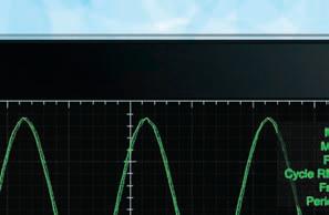
Figure 1—Asynchronous serial transmissions begin with a logic-low start bit (12 V on RS-232). Eight data bits follow with an additional logic-high stop bit (–12 V on RS-232). Since no clock is actually sent, each device must agree on the bit time used (bitrate).
Arlo’s 10-minute pre-story about being arrested for littering turns out to be a crucial part of the second 10 minutes of the song, which are about the draft. The whole idea here is that sometimes you need a little context or things just don’t make sense. Recently, while working on a precipitation measurement system (“Quantifying Precipitation: A Device to Measure Rainfall Volume,” Circuit Cellar 258, 2012), I realized how useful the right tools were for the design process. In that case, I wanted to use I2C or SPI as the medium for communicating with the smart sensor I developed to measure water. This is a “chicken or the egg” situation, as I didn’t have the application that would ultimately be using the sensor, so I had no way of developing the sensor’s communication. In the past, I’d built an RS-232-to-I2C dongle for speaking I2C with my PC. Lately, I’ve found the lack of RS-232 ports problematic.
After beginning a design for a USB-to-I2C dongle, I realized that a multiprotocol tool would make a great project. So, the project I’ll describe in this article gives you a tool to connect from a USB host to any of the following formats: I2C, SPI, RS-232/422/485, and Dallas (now Maxim IC) 1-Wire. A simple serial terminal application on your PC is all that’s necessary. You need to know the format of the data for each device to which you wish to talk. However, you are prompted with the general formats for I2C, SPI, and Dallas 1-Wire data, while RS-232/422/485 are strictly passed through.
TOO BIG FOR A DONGLE
Supporting all of these communication buses means lots of real estate. Most of that comes from connectors. I chose screw terminals as you can quickly connect up wires without any special headers or crimping pins (see Photo1). You might think to limit your build to only that bus of interest, but I highly recommend that you go all the way and not limit the potential for future investigations. Let’s take a quick look at each of these buses, starting with the RS-232/422/485.
RS-232/422/485
data clocking speed and data format (i.e., parity). RS-232 began as an interface between electromechanical teletypewriters and modems. The single-ended (ground return) ±12-V swing includes a –12-V or mark/idle state (logic 1) and a 12-V or space state (logic 0). The apparent confusion in state levels comes from the transmitter and receiver that invert the TTL levels to establish the bipolar swing. Start bits are therefore 12 V, and stop bits are –12 V. Twin unidirectional buses enable only two devices, as three (or more) devices would cause interference between multiple driving sources. The combination of a single-ended bus and data rate tends to limit the maximum useable bus length.
RS-422 uses a differential bus in an attempt to increase its immunity to interference and provide for much longer distances (up to 1,200 m) between devices. These transmitters/receivers operate on 5 V and eliminate the need for ±12-V supplies. Like RS-232, RS-422 uses twin unidirectional buses for data traffic. However, with RS-422 came multi-drop capabilities. This enables a master device to talk with multiple slave devices because transmitters can disable their drivers to prevent interfering with one another’s responses.
RS-485 is similar to RS-422 in that it uses the same differential bus, but the bus is reduced to a single differential pair. This means that data flow is now bidirectional and all transceivers must share the same bus. Only one device can talk on the bus at any time. Everyone must keep their drivers disabled until the bus is free (has been in an idle state for at least 1-byte time.) When used over large distances, such as between buildings, it is common to use an isolation circuit at one end to prevent differences in building grounds from exceeding acceptable limits.
The differential bus should be terminated with 120 Ω at each end of its length. If there is a possibility that all drivers are disabled, you should also ensure that the bus remains stable and in the idle state without a driver by pulling up the 5-V node and pulling down the 0-V node.
In most cases, you will only have to set the data rate for communication. Whatever data rate you choose at the PC application will be used on the microcontroller’s UART. The UART is preset for 8 data bits and no parity. The driver for RS-485 is disabled whenever data isn’t being sent and will only be enabled if the receiver has been in an idle state for 10 bit times to prevent bus collisions.
All these converters use same data format, an asynchronous data byte sent least-significant bit (LSB) first surrounded by a start and stop bit used for maintaining synchronization (see Figure 1). All devices on the bus must agree on the
SDA
SCL S
Start condition 1–7 8 9 1–8 9 P
Address Write ACK Data ACK Stop condition
Figure 2—The I2C bus uses two I/O bits, SCL (clock) and SDA (data). This format requires nine clock cycles, eight for information and one for acknowledgement for each byte passed.
I2C
When Philips needed a way of interfacing peripherals to a microcontroller without using its address and data buses it created the inter-integrated circuit bus, or I2C as we
SS CPOL=0 CPOL=1
CPHA=0
CPHA=1 Cycle #
MISO
MOSI z
z 1 2 3 4 5 6 7 8
1 2 3 4 5 6 7 8
1 2 3 4 5 6 7 8 z
z
Cycle #
MISO
MOSI z
z 1 2 3 4 5 6 7 8
1 2 3 4 5 6 7 8
1 2 3 4 5 6 7 8 z
z
Figure 3—The SPI bus uses four I/O bits, SCK (clock), MISO (data), and MOSI (data), along a with slave select (SS) for each slave peripheral connected. This format requires only eight clock cycles for each two bytes passed, one byte in each direction.
difference between the 7-bit address and the first byte’s address value. This value consists of the 7-bit address shifted left one bit (bits 7:1). The LSB (bit 0) is set for a read and cleared for a write command. So, for an address of 0x7F, the actual value sent would be 0xFF for a read command and 0xFE for a write command. After the eighth bit sent by the master, the slave must acknowledge receipt of the byte by forcing SDA low during the ninth bit time. If the command was a read and the slave is supplying the data on SDA, then it is the master’s responsibility to supply an acknowledge to the slave. This also tells the slave to continue sending additional data. When an acknowledgement does not occur, transmission will cease. Should the slave need more time to process a request before it can send (or receive) data, it can signal this to the master by forcing SCK low. The master must pay attention to the SCK line’s actual state. It is in control of SCK. But if it finds that after releasing the SCK line (enabling it to go high via the pull-up on know it today. The I2C bus consists of two bidirectional the bus) it is not high, it knows the slave is asking for logic-level lines—SCK (clock) and SDA (data)—that have more time and it will wait for the SCK to go high before 1.5-KΩ nominal pull-ups. Drivers for each line are open continuing. Note: This is a dangerous act for a slave to collector (can only drive the bus low). This synchronous perform as it can permanently disable further communiserial bus uses a special message format that includes an cation if it hangs in this state. To prevent this, use a address and data byte(s) as shown in Figure 2. The idea watchdog timer (WDT) to perform a reset on the slave if for this short-distance intraboard connection system was execution is caught in an endless loop. that each peripheral would be manufactured with its own In general, there are two kinds of I2C peripheral address to which it would respond. This enables the mas- devices, those that require their register pointer to be set ter (microcontroller) to speak with a specific slave and those that don’t. When a device requires its pointer (peripheral) without interference from other devices, all to be set, it will set the data pointer using the first data connected to the same two-wire bus. The master’s first byte of any write transfer. Otherwise, it will be initialbyte contains an address and read/write request. Periph- ized to zero at the start of each transfer. Data bytes will erals look for their personal address and process the data be written to or read from the indirect address of this that follows based on the read/write request. Other auto incrementing pointer. peripherals remain silent until they see a request that includes their address.
So, how does a slave know when a first byte is sent since the value of an address can look just like data? There is a special relationship between the SCK and SDA lines that make up the two-wire bus. During address/data transfer, SDA will only change state while SCK is low. Should a peripheral ever see SDA change while SCK is high, it stops all activity and gets ready for an address transmission. Logically, there are two possible cases where SDA changes while SCK is high. If SDA falls, this indicates the start of a message. If SDA rises, this indicates the stop or end of a message. The item that seems to cause the most confusion is the
Write 1 A
C Master sample E F Figure 4—The 1-Wire bus uses a single I/O bit to supply power to the peripherals (while the bus is high) and for bidirectional data transfers. Data is passed using timeslots. A timeslot begins when the idle high bus is pulled low for 1 µs. Any timeslot that remains low for a minimum of “E” and maximum of “C” is considered a “0.”
B Write 0 Read Reset Waveform legend
D Master sample
J Master Resistor pull-up Slave H G I

Figure 5—This project’s schematic has a number of user-installed jumpers used to configure the operating mode and provide flexible termination and option selections. All power is supplied by the USB connection. Screw terminals are provided for each bus.
SPI
Motorola chose a full-duplex scheme using four logiclevel connections (see Figure 3). Dubbed the serial peripheral interface (SPI), it is based on a master that supplies a synchronous clock (SCLK), two data lines— one out (MOSI) and one in (MISO), and a slave select (SS). When multiple devices are attached to a SPI bus, one SS is required for each slave peripheral. While this eliminates the overhead of having to communicate an address, it requires more I/O lines in systems that have a large number of peripherals connected. The data format is simple, the master provides eight data clocks and one data byte is transferred from the master into the slave and at the same time one data byte is transferred into the master from the slave.
You may see these signals labeled as SCK, SDI, SDO, or CS (or other morphed conventions). These alternatives are slightly less informative. It’s common to get inputs and outputs confused between a master and its peripherals. The MISO and MOSI designations leave no doubt in the signal’s direction. What seems simple on the surface does require some agreement on signaling format. There are actually four possible modes of operation. These have to do with clock polarity and data capture phase. The clock polarity (CPOL) can be high idle (=1) or low idle (=0). The data capture phase (CPHA) can be the first edge of the clock (=0) or the second edge of the clock (=1).
SPI uses no acknowledgement by a slave peripheral, so the master must assume all is well. A SPI slave can’t signal for more time, so it must be ready when the master begins. How does a peripheral know what to place in its output buffer before being asked? In some cases, it might have just a single response. If so, the peripheral might refresh its output with the latest data and it can be ready to transfer as soon as it sees the SS line go low. More likely, it will need to receive one data byte (or more) to understand what data it needs to provide. In any case, you can see that for each byte clocked out by the master, the data received from the peripheral may not contain any relevant information. And once the slave figures out what it needs to return, additional clocks are required by the master to get that data from the slave. During these clocks, the data coming from the master might be irrelevant.
What this all means is that you must have intimate knowledge of the slave device and its requirements for
Listing 1—The sign-on of each mode of operation. I will use this to jog my memory on the formatting and commands available the next time I try to use it.
USB to SPI Mode
To write data to a SPI register use the format... <command><sp><8-bit data>[<sp><8-bit data>]<CR> You will receive 1 byte for each byte sent. Dummy bytes may be necessary to retrieve additional bytes. You must know the data format for the device connected.
M? to query SPI M(ode) M=0 to use 0 M=1 to use 1 M=2 to use 2 M=3 to use 3 Presently M=0 K? to query I2C/SPI K(bps) K=0 to use 100 K(bps) K=1 to use 400 K(bps) K=2 to use 1000 K(bps) Presently K=0 H? to query H(ex) Data Format H=0 to use (3 Decimal Digits 000-255) H=1 to use (2 Hexadecimal Digits 00-FF) Presently H=0 ? ----------------------------------------------------------USB to I2C Mode
to write data to an I2C address use the format... W <address><sp><data>[<sp><data>] remember... if the I2C device uses registers, the first data byte updates the register pointer. to read data from an I2C address use the format... R <address><sp><dummy>[<sp><dummy>] use dummy data for each byte you want to read. remember... if the I2C device uses registers, update the register pointer with a write before reading. remember... to use the proper data format 2/3-digits S? to query I2C Bus status Presently I2C bus is Idle I? to query I(2C) address length I=0 to use 1 byte (7-bits) I=1 to use 2 bytes (10-bits) Presently I=0 K? to query I2C/SPI K(bps) K=0 to use 100 K(bps) K=1 to use 400 K(bps) K=2 to use 1000 K(bps) Presently K=0 H? to query H(ex) Data Format H=0 to use (3 Decimal Digits 000-255) H=1 to use (2 Hexadecimal Digits 00-FF) Presently H=0 ? ----------------------------------------------------------USB to RS232/TTL/422/485 Mode
All characters go between the USB and the UART. The UART data rate is set by the USB application. 3 escape characters ‘~~~’ received from USB triggers communication. There is no “one size fits all” for SPI communication. The data transfer is simple, but the format of the message is specialized for each peripheral.
1-WIRE
If SPI with its four-wire bus is simple, and I2C with its two-wire bus is minimalistic, then what would Dallas’s 1-Wire bus be known as? You might call this bus “vampirous.” It must be noted that SPI and I2C both require power and ground connections in addition to their noted number of signal (bus) lines. The 1-Wire bus includes only an additional ground connection, as device power is drawn from the one bidirectional bus line. Like I2C, this bus is pulled up to VCC and driven low with open-collector drivers. In its idle pulled-up state, the bus supplies attached devices with parasitic power.
The communication’s format is based on time slots (see Figure 4). To begin communication, the master must get attached devices listening by producing a reset pulse consisting of a logic-low level on the bus for a minimum of 480 µs. All devices will respond to the release of the reset pulse within 60 µs with a logic low for at least 60 µs. The master monitors for this “presence” signal to determine if there is anybody out there to talk to. Any device with an “alarm” may hold a logiclow state for at least 960 µs. No “good” device should hold the bus low for longer than 3,640 µs. This would indicate a short on the 1-Wire bus and would require user intervention. The absence of “presence” or “alarm” would indicate no devices are connected. Most 1-Wire commands are 1 byte in length and data is in 8-byte groups. While we haven’t discussed 1-Wire slave devices, at this point, you can imagine that if a bus contains multiple devices they would (and they will) interfere with one another.
The master can send the command byte 0x33 to retrieve a device’s 8-byte ROM identity code. It does this by sending the command byte LSB first. Each bit time is a minimum of 480 µs. To send a “1,” the bit time begins with a 1-µs logic-low pulse. To send a “0,” the pulse must be a minimum of 60 µs. Slave devices sample the logic-low times to determine the bit values. If the slave recognizes the command, it will respond with (in this case) its 8-byte ROM value. The master must


(0x55) requires an additional 8 bytes of the device you are interested in. All devices compare these 8 bytes to their own ROM identity code. All devices that don’t match this code will go silent and remain offline until a reset pulse is again issued by the master. But, if you don’t know the code to start with, then what? The SearchROM command is actually a software routine that uses a tree search, systematically trying MatchROM commands for every possible family and serial number. A quick search time is accomplished by limiting a branch search to only those that have conflicts. (Remember that bad CRCs can indicate multiple device interactions.) You can learn more about this in Maxim Integrated Products’s “Application Note 187, 1-Wire Search Algorithm.”
The ROM identity code may be all you need (e.g., if your door lock application only needs to recognize when an i-button has been touched to the bus). However, many 1-Wire devices have other functions as well. To explore these, there is a second set of commands used once you have made contact with one specific device.
MULTITOOL
Figure 6—This is a breakdown of the relative code size required to support each of the application’s functions. “What started out as a way to get my serial-to-I2C testing dongle connected to my serial portless laptop turned into a USB-to-multiprotocol project. I took the USB-to-serial circuit/code I used to help explain the inner workings of USB in my article series ‘Application Communication with USB’ (Circuit Cellar 239, 240, and 241, 2010)and adapted it to include RS-422/485, I2C, SPI, and 1-Wire. This tool is all you need to connect your PC’s USB port to a test circuit that requires one of these protocols.”
Percentage of code space I2C SPI Free 1-Wire USB Miscellaneous Help
What started out as a way to get my serial-to-I2C testing dongle connected to my serial portless laptop turned into a USB-tomultiprotocol project. I took the USB-to-serial circuit/code I used to help explain the inner workings of USB in my article series “Application Communication with USB” (Circuit Cellar 239, 240, and 241, 2010)and adapted it to include RS-422/485, I2C, SPI, and 1-Wire. This tool is all you need to connect your PC’s USB port to a test circuit that requires one of these protocols. The circuit in Figure 5 uses screw terminals to enable separate bus connections for each format without special crimping tools. You could cut the number of connectors in half if you put all the available signals in one row. And, as long as your labeling is clear, you would just connect to the signals associated with the protocol of interest.
For the simple pass through of serial data, you have a choice of connections for TTL and RS-232 serial (Maxim Integrated Products MAX232 5-V powered, multichannel RS-232 driver/receiver), RS-485 (bidirectional differential pair using a Maxim MAX481 low-power transceiver for RS-485 and RS-422 communication), and RS-422 (twin unidirectional differential pairs using two MAX481s). The RS-422/485 differential buses have termination and pull-up/down resistors that are jumper-enabled. Since the RS-485 bus carries bidirectional data, its transmitter is only enabled when the bus is idle. All UART functions are set up through the USB interface. That is, when you open a USB connection at some data rate, the UART in the circuit’s microcontroller is initialized to the same data rate.
If you are familiar with modem operation, you know that since all data is just passed through, there is normally no way to enter any commands to the circuitry. So, a particular series of characters (e.g., ~~~) was chosen that would halt the pass-through process and enable any characters that followed to be interpreted as a command, until it found, say, a “carriage return” <CR>. While the circuit’s UART is set up via the terminal application program on the PC, there really are not any commands necessary. However, I instituted this protocol anyway to enable the user to invert the data out of the UART. This is sometimes used to invert the TTL data so it can be
connected directly as a subset of RS-232C. Refer to the sign-on/help captures in Listing 1 and Figure 5 to see which commands are available in each of the four modes.
Unlike the pass-through mode of RS-232/422/485, all the other protocols are all totally command based. The microcontroller has an I2C peripheral that eases the implementation. No additional ICs are required as this is a logic-level bus. Note that 1.5-kΩ pull-up resistors can be jumper-enabled for the clock (SCK) and data (SDA) bus lines.
This microcontroller also has a SPI that eases this implementation. No additional ICs are required as this is a logic-level bus. All four lines of the bus are bipolar so pull-up resistors aren’t required.
The 1-Wire mode is not supported by any of the microcontroller’s peripherals. Although it is easily implemented using a Dallas Semiconductor serial-to-1-Wire interface DS2480B chip for less than $6, where’s the fun in that? It only takes one I/O bit and a bunch of supporting code to do it all in software. I’d used both methods in
past projects and forgot the amount of code necessary. Some of the parts can be rather complicated and many commands are special to a particular part. I implemented only the basic functions needed to get access to a part when multiple parts were on the same bus. Of these, I included the ReadROM, SkipROM, SearchROM, MatchROM, and ReadMemory.
Families of 1-Wire devices are grouped and identified by the first byte in the ROM code. A unique 6-byte serial number follows the family code with a 1-byte cyclic redundancy check (CRC) of the first 7 bytes appended as a quality check on the total 8-byte packet. The 8-bit CRC uses the X8 + X5 + X4 + 1 polynomial. Refer to my 2011 article “Error Checking” to learn more about CRCs (Circuit Cellar 250).
TROUBLE IN PARADISE
One of the things that constantly gets me in trouble is documentation. It seems as though users have an aversion to reading manuals. While I tend to pile all owners’ manuals in one place, I can never seem to find the one I need. Or, in the case of a project I built, there isn’t one (except for maybe the column itself). When I pull out an old project to assist with a new one, it takes me a while to remember (figure out) how to use it again. This time, I put in plenty of text help to aid me as I hedge against potential memory issues.
Presently, two of the three configuration jumpers are being used. This gives four different modes of operation, I2C, SPI, RS-232, and 1-Wire. When the circuit is powered up, it waits to receive a character (any key press) over the USB connection. This way, the sign-on message isn’t lost in transmission before a connection is made. The message identifies the mode of operation and displays a bit about the configured mode and the commands pertinent to it. There are five commands that give the user some flexibility, such as the two-digit hexadecimal or threedigit decimal data display format. These choices are stored in EEPROM and are nonvolatile. When you make a choice, the new value is compared to what is presently stored and the EEPROM is updated, if necessary. So, if you choose to work in the two-digit hexadecimal format, your preference is permanently noted and preset the next time the board is used.
The “?”—which is used as a prompt for user input— seems to be a reasonable choice for a help command. Entering a “?” will redisplay the sign-on’s help screen. In this application, I used roughly 88% of a Microchip Technology PIC18F14K50 microcontroller’s code space. Figure 6 shows a general breakdown of the code space used by the various support functions. In this family (PIC18FxxK50), the microcontroller with 20 pins has the most (8,000 words/instructions) available. If I want (or need) more than another 12% for additional functions, I’ll go to a 28-pin package as in the PIC18F46J50 family. This would have the advantage of up to an eight-time increase in code space with a slightly higher cost (approximately $3 versus $4). While the package size does increase a bit with a larger part, you don’t need a special adapter for debugging and you might make good use of the extra I/O.
I admit that I can think of a number of improvements that would increase this project’s flexibility and ease of use. Do you have a favorite interface that isn’t covered here and think would add to this project’s versatility? Your constructive comments can help make projects like these more useful for all of us. I
Jeff Bachiochi (pronounced BAH-key-AH-key) has been writing for Circuit Cellar since 1988. His background includes product design and manufacturing. You can reach him at jeff.bachiochi@ imaginethat now.com or at www.imaginethatnow.com.
PROJECT FILES
To download the code, go to ftp://ftp.circuitcellar.com/ pub/Circuit_Cellar/2012/259.
RESOURCES
J. Bachiochi, “Quantifying Precipitation: A Device to Measure Rainfall Volume,” Circuit Cellar 258, 2012.
———, “Error Checking,” Circuit Cellar 250, 2011.
———, “Application Communication with USB (Part 3): Assembly Code Finale,” Circuit Cellar 241, 2010.
———, “Application Communication with USB (Part 2): The Importance of Descriptors,” Circuit Cellar 240, 2010.
———, “Application Communication with USB (Part 1): The Enumeration Process Explained,” Circuit Cellar 239, 2010.
I2C Bus, www.i2c-bus.org/addressing.
Maxim Integrated Products, “Application Note 126, 1-Wire Communication through Software,” 2002, www.maxim-ic.com/app-notes/index.mvp/id/126.
———, “Application Note 187, 1-Wire Search Algorithm,” 2002, www.maxim-ic.com/app-notes/ index.mvp/id/187.
SOURCES
DS2480B Serial-to-1-Wire line driver, MAX232 drivers/receivers, and MAX481 transceivers
Maxim Integrated Products, Inc. | www.maxim-ic.com
PIC18F14K50 Microcontroller and PIC18F46J50 family of microcontrollers
Microchip Technology, Inc. | www.microchip.com February 2012 – Issue 259
February 2012 – Issue 259 PRIORITY INTERRUPT
by Steve Ciarcia, Founder and Editorial Director
TBusiness in the Cloud? here’s a lot of talk these days about freeing the user from the confines of a particular device via “cloud computing.” A typical example is Apple’s “i” family of devices where you can buy a song on iTunes with your iPhone, and then also play it on your iPad or home computer. Similarly, you can take a picture on any of these devices and share it seamlessly on all the others, or share it with your friends.
As a concept, this is a great thing, but it does have some strings. The song or picture, along with information about your ownership details, is stored out there “in the cloud,” or more specifically, somewhere on Apple’s servers. We don’t get excited over this because sharing photos, music, etc. among casual users isn’t considered “real data.” It’s merely an extension of the whole concept of social networking that is already relatively open.
The next level of cloud services from Google and others includes complete suites of web-hosted office applications (word processing, spreadsheet, database, etc.) and a lot more “real data” vulnerability. Along with services such as YouSendIt (file transmission) and Carbonite (file backup), the intention is for you to run your whole business on cloud servers and have instant ubiquitous access.
The question is: Are these services really up to the task of handling the data of a serious business?
Let’s talk about reliability first. Can you rely on important data being accessible the instant you need it? Well, if you take a look at the “Terms of Service” on any of the web services, they read pretty much like the end user license agreements (EULAs) we’ve all been reading for the past 30 years: this service is not guaranteed to do anything useful, this service is not guaranteed to be available, we are not responsible for any direct or consequential harm caused by this service, blah, blah, blah. This isn’t the sort of thing that should inspire confidence in anyone trying to start or run a business in today’s shaky economy.
At the very least, it means that for any data you put into a web application, you’d better make a private back-up copy and a back-up plan. You have to have access to that back-up copy via a means that does not involve the same application’s cloud server, an alternate ISP if the primary one fails (I have both cable and DSL for that reason), and a way to run the application elsewhere if the cloud business running the web app goes south.
But the bigger concern in my mind is the question of security. Who has access to the data you put into a web application, both now and in the future? Again, looking at those applications, I have yet to find a Terms of Service that promises any level of privacy for your data. Indeed, Google is particularly egregious in this area. Their Terms of Service (https://accounts.google .com/TOS) includes item #11, “Content License from You,” which states, “By submitting, posting, or displaying the content you give Google a perpetual, irrevocable, worldwide, royalty-free, and non-exclusive license to reproduce, adapt, modify, translate, publish, publicly perform, publicly display, and distribute any Content which you submit, post, or display on or through, the Services.” This is about as far from a promise of privacy as you can get!
You really need to think defensively about your data. Surely, Google harbors no intent to harm any business using its services, but with tens of thousands of employees, it’s hard keep track of the one among them with internal access to your data who is less scrupulous. Without concrete liability for misappropriating or deleting client data, can you trust placing your confidence and livelihood in an illusion of credibility and a mere promise of service? Yes, this is a harsh statement, but show me where these guys take responsibility even if they screw up everything.
Be proactive with sensitive business files! When using file transmission or storage services, either encrypt (and/or digitally sign) the data and/or deal only with companies that understand the real issues involved. One good example is Intuit, a company that provides accounting services to small businesses. (Carbonite and YouSendIt also fall into this category.) They devote an entire section of their website (http://security.intuit.com) to the issues of client privacy and data security.
The bottom line is that existence in the “cloud” is an up-and-coming trend, both personally and commercially. Always read the terms of service and privacy/security documentation of any web service you’re considering using and carefully evaluate which kinds of data you’re going to put out there. But most of all, in this wild and wooly age of botnets and malicious intent, make sure you have an independent copy and a back-up plan for any data you consign to the ether.
steve.ciarcia@circuitcellar.com
CIRCUIT CELLAR® • www.circuitcellar.com


Also Available: