93 minute read
履带起重机操作手册


Ser. No. 7 8
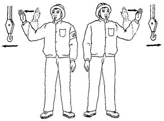
Signal Rotate Lower load slowly
Description
Turn left: With right forearm vertical, the palm of the hand facing outwards, lower the forearm sideways horizontally, fingers pointing at the direction of rotation.


Turn right: With left forearm vertical, the palm of the hand facing outwards, lower the forearm sideways horizontally, fingers pointing at the direction of rotation.
With arm extended downwards with a 30° angle to the body,palm of the hand facing downwards, wave hand down repeatedly.
Illustration
Ser. No.
9
Signal Rotate slowly
Description
Turn left: With right forearm vertical, the palm of the hand facing outwards, move forearm horizontally and repeatedly, fingers pointing at the direction of rotation.
Turn right: With left forearm vertical, the palm of the hand facing outwards, move forearm horizontally and repeatedly, fingers pointing at the direction of rotation.
10
Indicate load lowering position
Extend the fingers to point at the position where the load should fall on.
Illustration
ZCC1100H Crawler Crane
Operator’s Manual for Crawler Crane
Operator’s Manual for Crawler Crane
履带起重机操作手册
Ser. No. 11 12 13
Signal Raise boom Lower boom Raise boom slowly
Description
With arm stretched sideways horizontally, thumb pointing upwards, the remaining fingers closed, wave forearm up.

With arm stretched sideways horizontally, thumb pointing downwards, the remaining fingers closed, wave forearm down.
Bend the left arm. Move the thumb up and down, pointing upwards Place the right arm above it.


Illustration
Ser. No. 14 15
16
Signal Lower boom slowly Stop Emergency stop
Description
Bend the left arm. Move the thumb up and down, pointing downwards Place the right arm below it


Stretch out one arm horizontally. The palm faces downwards Swing the arm to one side of the body.
Stretch out both arms horizontally. The palms face downwards Swing the arms to both sides of the body.
Illustration
ZCC1100H Crawler Crane 3-55
履带起重机操作手册
Operator’s Manual for Crawler Crane
Ser. No. 17
Signal End of a movement
Description
With fingers extended, cross both hands before the forehead.
Illustration
The crane operator must watch the load before carrying out any movements and especially pay attention to the hook or hook pulley when moving the crane without load. If it’s difficult to do so, the operator can only operate it according to the signal given by the signal man, which can be conducted by hand signal or interphone. Vigilance is needed no matter which method is used to avoid misunderstanding.
Caution
(1) We recommend using the hand signals illustrated above. However, users can decide on their own hand signals depending on actual condition, as different countries and regions may differ in the expression of hand signals.

(2) Hand signals must first be discussed and mutually agreed upon and clearly executed. Misunderstanding of hand signals may lead to serious accidents.
Caution
In any case, national traffic regulations must always be observed when operating abroad.
ZCC1100H Crawler Crane
Operator’s Manual for Crawler
Operator’s Manual for Crawler Crane
Chapter 4 Crane Operation
4.1 Operati ng and control instruments
4.1.1 Operator’s cab, overview
The arrangement of operating and control instruments in the operator ’s cab is shown in the figure 4-1. For detailed information, please see table 4-1.
Table
Description of operating and control instruments
No.
Names of instruments
1 Winch monitoring system
2 Digital display system
Remarks
Monitor the working status of the winch and the condition behind the crane.
One is LCD screen of load moment limiter, and the other is LCD screen of electrical system. (For more information, please see section 4.2.)
3 Accelerator pedal Control the engine speed. Depress the pedal, the speed is increased; Release the pedal, the speed is returned to idle speed.
No. Names of instruments
Remarks
4 Electrical control box Arrange the electric elements.
5 Operating console
6 Right control lever
Arrange the switches for electric elements. (For details, please see section 4.1.2.)
Control the movements of hoisting winches 1 and 3, derricking winch and mounting cylinder. (For details, please see section 4.1.3.2)
7 Operator ’s seat It is adjustable. (For details, please see section 4.3.1)
8 Right control panel
9 Central unit of air conditioning
Arrange the switches for electric elements. (For details, please see section 4.1 5)
It is located at the back of the cab. (For details, please see Maintenance Manual.)
10 Right travel gear pedal Control the movements of right travel gear.
11 Left travel gear pedal Control the movements of left travel gear.
12 Free-fall brake pedal
Control the braking of hook in free-fall mode. (Only when the crane has free-fall function, can this pedal is fitted.)
13 Safety lever
Pull up the safety lever before the operator gets into or out of the cab, the power of crane is cut off, but the engine is not shut down.
Lower the safety lever before lifting operation, the crane is electrified, and the crane movements can be carried out.
14 Left control lever
Control the movements of hoisting winch 2 and slewing mechanism. (For details, please see section 4.1.3.1)
15 Left control panel Arrange the switches. (For details, please see section 4.1.4.)
4.1.2 Operating console
The switches on the operating console are detailed in the table 4-2.
Names of the switches
1 Power switch of electrical system
2 SetUp switch
3 Engine shutdown switch
4 Engine preheating switch
5
Derricking bypass switch
Remarks
Switch on or off the power supply of electrical system.
After overloading warning is triggered (100%<moment percent<110%), never spool up hoisting winch, and raise or lower the main boom. At this time, press this switch to release the limited movements.
Press this switch to shut down the engine.
W hen ambient temperature is less than -20℃, press this switch to preheat the engine.
After overloading warning is triggered (100%<moment percent<110%), never raise or lower the main boom. At this time, press “SetUp” switch. After the icon appears on the load moment limiter, turn the switch clockwise and keep it there. After the icon appears,main boom can be raised and lowered.
No. Names of the switches
6 Lowering bypass switch
7 Hoisting bypass switch
Caution
Remarks
After lowering warning is sent, never reel off hoisting winch. Turn the switch clockwise and keep it there at this time. W hen the icon appears on the load moment limiter, the hoisting winch can be reeled off.
After hoisting warning is sent, never spool up the hoisting winch Turn the switch clockwise and keep it there at this time. W hen the icon shows on the load moment limiter, the hoisting winch can be spooled up.
(1) After the engine is shut down, release the ignition starter switch to the initial position after 30s. Otherwise, the work hour of engine this time can not be saved.
(2) Return the shutdown switch to initial position before starting the engine.
As shown in the figure 4-3, the left is the operating board for left control lever. It is stuck on the left glass of the cab. The four directions shown on the right means that the control lever can be moved forwards, backwards, leftwards and rightwards. There are two buttons on the control lever. For their functions, please see the table 4-3.
Table 4-3 Operation of left control lever
No. Meaning of the symbol
1 Reel off H2
2 Extend mounting cylinder
3 Swing free running
4 Slew to right
5 Retract mounting cylinder
6 Spool up H2
7 Slew to left
8 High speed
Caution
Remarks
Push left control lever forwards, reel off H2.
Push left control lever forwards, extend mounting cylinder
Correspond to the right button on the top of control lever. Protect the boom against damage by reducing the side force acting on the boom.
Move left control lever to right, slew the superstructure to right
Pull left control lever backwards, retract mounting cylinder.
Pull left control lever backwards, spool up H2.
Move left control lever to left, slew the superstructure to left.
Correspond to the left button on the top of control lever. It is used to control the high-speed operation of slewing mechanism, H2 winch and left travel gear.
Avoid stopping slewing movements suddenly during operation. Otherwise, the load will shake violently.
4.1.3.2 Right control lever
Figure 4-4 Illustration of right control lever operation
As shown in the figure 4-4, the left is the operating board for right control lever. It is stuck on the left glass of the cab. The four directions shown on the right means that the control lever can be moved forwards, backwards, leftwards and rightwards. There are two buttons on the control lever. For their functions, please see the table 4-4.
No. Meaning of the symbol
1 Horn
2 Reel off H1
3 High speed
4 Reel off H3
5 Reel off derricking winch
6 Spool up H1
7 Spool up H3
8 Spool up derricking winch
Remarks
Correspond to the left button on the top of control lever. It is used to control the horn.
Push right control lever forwards, reel off H1.
Correspond to the right button on the top of control lever. It is used to control the high-speed operation of H1 winch, H3 winch and right travel gear.
Move right control lever to right, reel off H3.
Move right control lever to right, reel off derricking winch.
Pull right control lever backwards, spool up H1
Move right control lever to left, spool up H3.
Move right control lever to left, spool up derricking winch.
Caution
The horn can only be actuated in emergency condition to warn the person in the vicinity of the crane.
4.1.4
W hen the crane has free-fall function, the left control panel will be described in the table 4-5.
function)
No.
Names of the switches
1 Free-fall master switch
2 H1 free-fall switch
3 H2 free-fall switch
4 H3 free-fall switch
Remarks
Turn on this switch before any free-fall operation of hoisting winch.
In order to carry out free-fall operation of H1 winch, the operator must first turn on “free-fall master switch”, and then switch on “H1 free-fall switch”.
Control the free-fall operation of H2 winch. The operating method is the same as above.
Control the free-fall operation of H3 winch. The operating method is the same as above.
Danger
(1) If free-fall operation is not finished (i.e. the wind drum does not stop rotating), never set the free-fall switch of corresponding winch to the initial position.
(2) When the hoisting winch is controlled by control lever, never switch on any free-fall switches.
The right control panel will be described in the table 4-6
No. Names of the switches
1 Ignition key switch
2
Accelerator control knob
3
Manual accelerator switch
Remarks
Insert the key into the ignition key switch and rotate it clockwise to 1st position, then the power is turned on. Continue to rotate the key to the 2nd position, then the engine is started.
The engine rotational speed is adjusted through the knob under the manual accelerator mode.
Clockwise rotate the knob, the engine speed will increase.
Turn the switch clockwise, the accelerator control mode is changed into the manual control. At this time, the accelerator is controlled by the knob (No. 2 in the figure 4-6) rather than the accelerator pedal (No. 3 in the figure 4-1).
Caution
(1) Before starting the engine each time, first set the ignition key switch in initial position.
(2) The engine will be started after automatic preheating when it is cold. Moreover, delay start of the engine is normal.
Refer to figure 4-7 for the position of control panel on the roof of operator’s cab and refer to figure 4-8 for details
As to the functions of switches on the control panel, refer to figure 4-7.
T able 4-7 Description of switches on the control panel
No. Names of switches Functions
1 W asher switch Control the washer
2 Front windshield wiper switch” Control the front windshield wiper
3 Master lighting switch
4 “Working floodlight on the slewing table” switch
Turn it on the 1st position, the LED on instruments and control panel will light up. Turn it on the 2nd position, the working floodlights on the roof of operator ’s cab will light up.
The switch will work when the master lighting switch is placed on 2nd position. It will control all working floodlights on the slewing table, including lighting of monitoring system.
5 Derricking ratchet pawl switch
If derricking mechanism does not work for a long time, turn on derricking ratchet pawl switch, and then reel off derricking winch slowly until ratchet pawl is engaged into the ratchet wheel completely. At this time, the derricking rope can not be unwound continuously.
W hen there is a need to move the boom, turn off derricking ratchet pawl switch, and then spool up derricking winch to make ratchet pawl disengaged from the ratchet wheel.
6 H1 winch switch Turn on this switch to carry out H1 winch movements
7 H2 winch switch
8 H3 winch switch
Turn on this switch to carry out H2 winch movements, meanwhile turn off mounting cylinder switch
When the switch is turned off, you can operate derricking winch. W hen it is turned on, H3 winch movements can be carried out.
No. Names of switches Functions
9
Mounting cylinder switch
10 Oil cooling fan switch
11
12
W inch low-speed switch
Turn on this switch to operate mounting cylinder on main boom pivot section, and turn off H2 winch switch at the same time.
Turn on this switch to make the oil cooling fan work when there is a need to cool the hydraulic oil.
All winch movements will slow down after the switch is turned on.
Travel gear switch Turn on this switch to operate the travel gear.
Caution
(1) Never operate H2 winch and mounting cylinder at the same time.
(2) Never operate derricking winch and H3 winch at the same time
4.2 Instruction for digital display system
The description of digital display system is shown in the table 4-8.
Remarks
Display information about crane such as current load, boom length, boom angle and moment percent W hen abnormal conditions occur, the corresponding warning icons will flash.
Show the working status of crawler crane in real time. When abnormal conditions occur, the corresponding warning icons on the screen will flash. Monitor the main parameters of the crane and engine, and set the parameter of electrical system in real time.
4.2.1 Load moment limiter
As to detailed operation, refer to Load Moment Limiter Operating Manual.
4.2.2 Electrical system
The main screen of electrical system is shown in the figure 4-10.
The main screen is subdivided into five main areas.
a) Alarm functions b) Engine information c) Monitored additional functions d) Pressure monitoring of hydraulic system e) Function keys area
4.2.2.1 Alarm functions
The screen of alarm functions will be described in details in the table 4-9.
No. Meaning of the icons
1
Icon “Engine oil pressure”
2 Icon “Engine coolant temperature”
3
4
Icon “Max. main boom angle”
Icon “Detection of slewing fixing pin”
Remarks
When engine oil pressure is less than 0.06MPa, this icon will flash
When engine coolant temperature is higher than 98℃, this icon will flash.
When main boom angle reaches the maximum value, this icon will flash.
When the slewing fixing pin is not pulled out, this icon will flash.
5 Icon “Oil pipeline clog” When oil pipeline is clogged, this icon will flash.
6
7
8
9
Icon “Lower limit switch on H3 winch”
Icon “Lower limit switch on H2 winch”
Icon “Upper limit switch on H2 winch”
Icon “Lower limit switch on H1 winch”
10 Icon “Upper limit switch on H1 winch”
When there are only three windings of wire rope left on H3 winch, this icon will flash.
When there are only three windings of wire rope left on H2 winch, this icon will flash
When the load hook comes into contact with the hoisting limit switch weight during its upward movement, this icon will flash.
When there are only three windings of wire rope left on H1 winch, this icon will flash.
When the load hook comes into contact with the hoisting limit switch weight during its upward movement, this icon will flash.
4.2.2.2 Engine information
The screen of engine information will be described in detail in the table 4-10.
1 Engine speed and working time Show current engine speed and total working hours 2 Engine coolant temperature Show engine coolant temperature 3 Engine oil pressure Show engine oil pressure 4 Fuel level Show fuel level in the fuel tank
4.2.2.3 Monitored additional functions
Screen of monitored additional functions
The screen of monitored additional functions will be described in detail in the table 4-11.
No. Monitored additional functions
1 “Free-fall function” warning
2 “H1 f ree-fall” warning
3 “H2 free-fall” warning
4 “H3 free-fall” warning
5 Battery voltage
6 Crane inclination
Remarks
The icon will flash after the free-fall master switch (No.1 in figure 4-5) is turned on
The icon will flash after H1 free-fall switch (No.2 in figure 4-5) is turned on.
The icon will flash after H2 free-fall switch (No.3 in figure 4-5) is turned on
The icon will flash after H3 free-fall switch (No.4 in figure 4-5) is turned on
Show the current voltage of crane battery
Show the inclination of crane to the horizontal in longitudinal and lateral direction
Note: The traveling direction of crane is taken as positive direction.
4.2.2.4 Pressure monitoring of hydraulic system
The pressure monitoring of hydraulic system will be described in details in the table 4-12.
4.2.2.5 Function key area
4-15 Function key area
The function key area will be described in the table 4-13.
Description of function key area
No. Function keys
1 Key “Main screen”
2 Key “I/O screen”
3 Key “Parameter adjustment”
4
Key “Parameter resetting”
5 Key “Work status”
6
7
8 Key “Enter”
Remarks
Press this key in any other screen, the system can be switched into “main screen” directly.
Press this key to enter “I/O screen”. In this screen, all the input/output points of PLC can be checked.
Press this key to enter “Parameter adjustment” screen, then you can adjust relevant parameters of main motions.
Press this key to enter “Parameter resetting” screen, then you can restore all parameters to the factory setting.
Press this key, the system can be switched into “work status” screen. In this screen, the working status for all crane movements can be checked.
Page up
Page down
Confirm the previous operation or save the modified parameters.
4.3 Startup of the crane
4.3.1 Adjustment of crane operator’s seat
a) Vertical adjustment of headrest b) Adjustment of armrest c) Horizontal adjustment of seat
The height of headrest is adjusted manually with proper strength.
The height of armrest can be adjusted by the adjusting knobs.
Pull the lever upwards; Move the seat to required position; Release the lever.
d) Adjustment of seat height
There are two levers to adjust the seat height. The left lever adjusts the height of the front part of the seat, and the right lever adjusts the height of the rear part of the seat. Pull the left lever upwards, the front part of the seat is raised up. Pull the right lever upwards, the rear part of the seat is raised up.
e) Adjustment of backrest
Pull the horizontal adjustment lever upwards, pull the backrest to proper position and release the lever.
Adjustment
4.3.2 Checks before startup
The f ollowing checks should be performed before startup of the engine.
a) Check oil filter and oil level
1) Oil level of diesel engine
2) Oil level of hydraulic oil tank
3) Oil filter on hydraulic oil tank b) Check coolant level c) Check the general conditions of the crane
Add coolant to the rim on the filling nozzle.
Before starting up the crane, the operator must ensure that the following conditions are fulfilled:
1) The crane is horizontally aligned.
2) The gear of the slewing ring must be clean and greased
3) The air inlet of oil coolant radiator is not blocked.
4) All cowlings and covers on the sides must be closed and locked.
5) No person or object is within the slewing radius of the crane.
6) No ice or snow is on wire rope, winding drum and limit switches.
7) There are no loose parts on slewing table or on the boom.
8) The shutoff valve on hydraulic oil tank should be opened.
9) The battery master switch must be placed in “ON” position. Otherwise, the whole machine can not be energized.
Danger
(1) Never check the coolant level before the engine is cooled down. Otherwise, you may get scalded.
(2) Before carrying out any boom movements, make sure that there are no loose parts on the boom such as pin, or retaining spring. Otherwise, these falling parts may hit persons or other objects.
4.3.3 Turn on power supply
Insert ignition key into ignition lock and turn it clockwise to the 1st position, then the power supply is turned on. See the figure 4-21
4.3.3.1 Checking main screen of electrical system
After the power supply is turned on, press the power switch (no. 5 in the figure 4-2) on the operating console, both the LCD screen of load moment limiter and LCD screen of electrical system are started. At this time, check the following items as shown in the figure 4-22.
Items to be inspected a) Check engine oil level; b) Check if slewing fixing pin is pulled out; c) Check hoisting limit switches on H1, H2; d) Check if free-fall switches are switched off; e) Check the maximum main boom angle; f) Check crane battery voltage; g) Check crane inclination.
Caution
(1) Add diesel oil in time if the fuel level is too low.
(2) The maximum in-service wind speed should not exceed 9.8m/s.
The maximum out-of-service wind speed should not exceed 21m/s when the crane is only fitted with main boom.
The maximum out-of-service wind speed should not exceed 15m/s when the crane is fitted with main boom and fixed jib.
If wind speed reaches or exceeds these values, the entire boom should be lowered down.
(3) The inclination range for the superstructure: the inclination should be less than 1% in both lateral direction and longitudinal direction. If this range is exceeded, the crane operator must adjust the crane to horizontal position firstly.
4.3.3.2 Checking load moment limiter
a) Check if the load moment limiter is working properly.
b) Correctly set work mode on the screen of load moment limiter.
c) Check if overloading occurs.
Operator’s Manual for Crawler Crane
4.3.4 Operation of air conditioning in operator’s cab
The crane operator’s cab can be heated or cooled according to the expected temperature, and the control panel is located above the wallboard on the right side of the cab. Refer to figure 4-23
4.3.5 Horn
Press horn switch before starting the work to check if the horn can be sounded. See the figure 4-24
Horn switch
4.3.6 Start of engine
Insert ignition key into ignition lock and turn it clockwise to the 2nd position, the engine can be started.
After the engine is started, check if the f ollowing items of engine are normal. See the figure 4-26
Check of engine parameters
Items to be inspected: a) Check if the engine speed is normal. b) Check if the engine coolant temperature is normal. c) Check if the engine oil pressure is normal.
Caution
(1) Compared with routine conditions, it takes longer time to preheat the engine automatically in cold weather. This is a normal phenomenon.
(2) Do not use accelerator when starting engine.
If the engine fails to start after approx. 5s, slowly depress the accelerator pedal all the way down.
If the engine can not be started within 5-10s, give up the starting attempt and wait approx. 1 minute before trying again.
If the engine still can not be started continuously for three times, stop starting engine at once and check it for fault.
If the temperature of engine is high, do not depress accelerator pedal when starting the engine to avoid black smoke discharging.
After the engine starts, release ignition key switch at once to let it return to initial position, and check the parameters of the engine at the same time.
(3) When ambient temperature is less than -20℃ , start the engine via cold-start device. Before starting cold-start device, the operator must first turn off power switch of electrical system (No.1 in the figure 4-2), set ignition key switch (No.1 in the figure 4-6) in 1st position to turn on the power supply, and then switch on cold-start rocker switch (no. 7 in the figure 4-2).
Only after running cold-start device for 10mins, the engine can be started.
If engine coolant temperature is slightly lower than normal in cold weather, start cold-start device to increase coolant temperature.
(4) The crane engine can only become full loaded when it achieves the running temperature.
Operator’s Manual for Crawler Crane
4.4 Safety device
The crane operator must check all safety devices for functional work before every crane operation.
Danger
Operating crane with faulty safety devices is prohibited!
4.4.1 Emergency stop button
As soon as this emergency stop button is pressed, a) The electrical control system is switched off and the diesel engine shuts down; b) All crane movements stop immediately.
Danger
The emergency stop button must only be used in case of emergency and not as a normal procedure for shutting down the diesel engine!
If an emergency stop is triggered while a load is being lifted, there may be a risk of accident owing to swinging of load.
Operator’s Manual for Crawler Crane
4.4.2 Battery master switch
Battery master switch is located in the battery box on the slewing table. Set battery master switch in “OFF” position during long-time work breaks so as to prevent the electricity of battery from discharging excessively.
4.4.3 Flashing light
When the crane is electrified via ignition key switch, the flashing light will light up. It will warn people around and shows that the crane is working.
4.4.4 Load moment limiter
When permissible load moment is exceeded, the crane movements which will increase load moment will be cut off, and only those movements that will decrease load moment are allowed. However, the presence of load moment limiter does not relieve the crane operator of his duties and responsibilities for safe crane operation. Before lifting a load, he must know the approximate weight of load and decide if the crane is in a position to carry out this job with the help of lifting capacity chart.
Danger
The load moment limiter must be adjusted before using the crane to the current set up condition in accordance with the lifting capacity chart. Only in this way can it be able to fulfill its protective task.
If crane operator does not observe this safety obligation, the crane may overturn and may be damaged beyond repair, despite the load moment limiter is working normally. The load moment limiter can not monitor and control all possible operating conditions; this is still primarily the responsibility of the operator.
Caution
The “Bypass” in this chapter means that the limited movement is allowed to move towards dangerous direction via bypass switch after the alarm is sent out and the system cut off the dangerous movement. This does not mean the alarm is canceled.
4.4.4.1 Moment percent between 100%-110%
If the moment percent shown on the load moment limiter is between 100% and 110%, it means that the actual load of crane reaches 100% - 110% of the rated load. At this time, crane movements “spool up H1, H2 and H3”, “derrick boom up and down” are cut off, the tricolor light sends out yellow and red warning and the buzzer sounds continuously.
Caution
Bypass those limited movements in accordance with the following methods:
(1) Turn bypass switch (in the electrical control box of slewing table) clockwise until the icon appears on the load moment limiter. At this time, the limited movement “derrick boom up” is bypassed. However, the tricolor light sends out red warning and the buzzer sounds continuously.
(2) Press “Setup” switch (No. 2 in the figure 4-2) on the operating console, the icon will appear on the load moment limiter if rated load is lifted. At this time, rotate derricking bypass switch (No. 5 in the figure 4-2) clockwise, the limited movement “derrick boom up” is bypassed. However, derricking speed is reduced, the tricolor light sends out yellow and red warning, and the buzzer sounds continuously. Press “Setup” switch (No. 2 in the figure 4-2) on the operating console, the icons and will appear on the load moment limiter if non-rated load is lifted. At this time, the limited movement “derrick boom up” is bypassed. However, derricking speed is reduced, the tricolor light sends out yellow warning, and the buzzer sounds continuously.
4.4.4.2 Moment percent more than 110%
If the moment percent shown on the load moment limiter is more than 110%, it means that the actual load of crane exceeds 110% of the rated load. At this time, crane movements “spool up H1, H2 and H3”, “derrick boom up and down” are cut off, the tricolor light sends out yellow and red warning and the buzzer sounds continuously.
Caution
Bypass those limited movements in accordance with the following method:
Turn bypass switch (in the electrical control box of slewing table) clockwise until the icon appears on the load moment limiter. At this time, all limited movements are bypassed. However, the tricolor light sends out red warning and the buzzer sounds continuously.
4.4.4.3 Moment percent less than 100%
When crane is not lifting the rated load, please see section 4.4.4.1.
Caution
(1) Once the limited movements are bypassed by bypass switch, their speeds will be reduced to 15% of original speed.
(2) Press “Setup” switch, the bypass of cutoff is valid. After the limited movement is bypassed, return the control lever for 10s, or press “Setup” switch again, or the engine stops, or the controller is electrified again, the bypass of cutoff is invalid. Press bypass switch, the bypass of cutoff is valid for 30mins. If the switch is pressed again, or the engine stops, or the controller is electrified again, the bypass of cutoff is invalid.
4.4.5 Boom angle indicator
Boom angle indicator is fitted on the lower rear end of main boom pivot section (i.e. on the right side of the crane operator’s cab). In this way, the operator, even in crane operator’s cab, can clearly read boom angle shown on the indicator.
4.4.6 Derricking limiter
It is used to detect main boom angle in real time according to the data collected by angle sensors. Once detected angle exceeds safe angle range, an alarm will be sent out and dangerous movements will be switched off so as to ensure safe crane operation.
a) Crane operation with main boom b) Crane operation with main boom and fixed jib
When main boom angle reaches the maximum value within the minimum radius, the crane movement “raise main boom” will be cut off automatically, the icon will appear on the load moment limiter, the tricolor light will send out yellow and red warning, and the buzzer will sound.
When main boom angle is less than 2° of the maximum angle, the buzzer will sound, but main boom can still be raised up.
The requirements for main boom angle under this boom configuration are the same as that under “Main boom” configuration. The fixed jib can be fitted in the angle of either 10° or 30° to main boom.
4.4.7 Lowering limiter
In order to prevent wire rope from being wound in the opposite direction after it is unwound completely, the lowering limit switches fitted on H1, H2 and H3 are triggered when there are only three windings of wire rope left on the drums. Under this condition, the buzzer will sound, the tricolor light will send out yellow and red warning continuously, and the icon appears on the load moment limiter. At this time, the movement of “reel off winch” is switched off, and only the movement of ‘spool up winch” can be carried out.
Caution
Bypass those limited movements in accordance with the following methods:
(1) Turn bypass switch (in the electrical control box of slewing table) clockwise until the icon appears on the load moment limiter. At this time, the limited movement “reel off winch” is bypassed. However, the tricolor light sends out red warning and the buzzer sounds continuously.

(2) Rotate lowering bypass switch (No.6 in the figure 4-2) clockwise until the icon appears on the load moment limiter. At this time, the limited movement “reel off winch” is bypassed. However, the tricolor light sends out yellow and red warning, and the buzzer sounds continuously.
Danger
(1) The lowering bypass switch or bypass switch is only used in commissioning and maintenance condition or to avoid accident occurring.
(2) If lowering limiter is bypassed, there is a risk of increasing accidents!
4.4.8 Hoisting limiter
The hoisting limiter is installed to prevent the hook pulley from colliding with the boom head. Before using the crane every time, inspect the switch by lifting the hook to the upper limit and colliding with the hoisting limit switch weight.
If the load hook comes into contact with the hoisting limit switch weight during its upward movement, the hoisting limit switch is triggered. Under this condition, the buzzer will sound, the tricolor light will send out yellow and red warning continuously, and the icon appears on the load moment limiter. At this time, the crane movements “spool up H1, H2 and H3” and “derrick boom down” are switched off.
Caution
Bypass those limited movements in accordance with the following methods:
(1) Turn bypass switch (in the electrical control box of slewing table) clockwise until the icon appears on the load moment limiter. At this time, the limited movements are bypassed. However, the tricolor light sends out red warning and the buzzer sounds continuously.
(2) Rotate hoisting bypass switch (No.7 in the figure 4-2) clockwise until the icon appears on the load moment limiter. At this time, the limited movements are bypassed. However, the tricolor light sends out yellow and red warning, and the buzzer sounds continuously.
Danger
(1) The hoisting bypass switch or bypass switch is only used in commissioning and maintenance condition or to avoid accident occurring.
(2) If hoisting limiter is bypassed, there is a risk of increasing accidents!
4.4.9 Anemometer
The anemometer fitted on the main boom or fixed jib head can detect the wind speed on the top of the boom in real time.
When the in-service wind speed exceeds 9.8m/s, the crane operation should be stopped immediately.
When the out-of -service wind speed for “Main boom” configuration exceeds 21m/s, the entire boom should be placed on the ground.
When the out-of -service wind speed for “Main boom with fixed jib” configuration exceeds 15m/s, the entire boom should be placed on the ground. The operator should constantly observe the wind speed displayed on the screen.
4.4.10 Crane inclinometer
Crawler crane is fitted with an electric inclinometer. The crane inclination can be shown on the screen of electrical system (No. 6 in the figure 4-13) in real time.
4.4.11 Checklist of safety device
Table 4-14 Checklist of safety device
1
The load hook of hoisting winch comes into contact with the hoisting limit switch weight during its upward movement. (take H1 winch as an example)
1. The crane movement “lift the hook” is cut off.
2. The icon flashes on the load moment limiter.
3. The tricolor light sends out yellow and red warning, and the buzzer sounds continuously.
1. Turn the bypass switch clockwise until the icon appears on the load moment limiter. At this time, the limited movement is bypassed. However, the tricolor light sends out red warning, and the buzzer sounds continuously.
2. Rotate hoisting bypass switch clockwise until the icon appears on the load moment limiter. The limited movement is bypassed. However, the tricolor light sends out red and yellow warning, and the buzzer sounds continuously.
1. When bypass switch is turned on, the speed of crane movement decrease.
2. When pressing the “hoisting bypass switch”, the speed of crane movement is kept the same.
1. The crane movement “lower the hook” is cut off.
2.
There are only three windings of wire rope left on the hoisting winch (take H1 winch as an example)
2. The icon flashes on the load moment limiter.
3. The tricolor light sends out yellow and red warning, and the buzzer sounds continuously.
1. Turn the bypass switch clockwise until the icon appears on the load moment limiter. At this time, the limited movement is bypassed. However, the tricolor light sends out red warning, and the buzzer sounds continuously.
2. Rotate lowering bypass switch clockwise until the icon appears on the load moment limiter. The limited movement is bypassed. However, the tricolor light sends out red and yellow warning, and the buzzer sounds continuously.
1. When bypass switch is turned on, the speed of crane movement decrease.
2. When pressing the “lowering bypass” switch, the speed of crane movement is kept the same.
3
90% ≤ moment percent ≤ 100%
The tricolor light sends out yellow warning, and the buzzer sounds continuously.
No work mechanism slows down.
No. Prerequisite limited movements
Bypass methods Movement speed
1. Turn the bypass switch clockwise until the icon appears on the load moment limiter. At this time, the limited movements are bypassed. However, the tricolor light sends out red warning, and the buzzer sounds continuously.
1. When bypass switch is turned on, the speed of crane movement decrease.
4
Overloading: 100% ≤ moment percent ≤ 110%
1. The crane movements “lift main/auxiliary hook” and “raise/lower boom” are cut off.
2. The tricolor light sends out yellow and red warning, and the buzzer sounds continuously.
2. Press “Setup” switch, the icon will appear on the load moment limiter if the load moment percent reaches 100%. And the movement “lift the hook” is bypassed. At this time, rotate derricking bypass switch clockwise, the limited movement “raise / lower boom ” is bypassed. However, the tricolor light sends out yellow and red warning, and the buzzer sounds continuously. Press “Setup” switch, the icons and will appear on the load moment limiter if the load moment percent is less than 100%. At this time, all movements are bypassed. However, the tricolor light sends out yellow warning, and the buzzer sounds continuously.
2. When “Setup” switch is pressed, and load moment percent is less than 100%, the speed of crane movement is not reduced.
3. When “Setup” switch is pressed, and load moment percent is 100%, the speed of crane movement is reduced.
5
Overloading: 110% ≥ moment percent
1. The crane movements “lift main/auxiliary hook” and “raise/lower boom” are cut off.
2. The tricolor light sends out yellow and red warning, and the buzzer sounds continuously.
Turn the bypass switch clockwise until the icon appears on the load moment limiter. At this time, the limited movements are bypassed. However, the tricolor light sends out red warning, and the buzzer sounds continuously.
The speed of crane movement is reduced.
No. Prerequisite limited movements
Bypass methods Movement speed
6 Main boom angle is less than minimum angle.
1. The crane movements “lift main/auxiliary hook” and “lower boom” are cut off.
2. The tricolor light sends out yellow and red warning, and the buzzer sounds continuously.
1. Turn the bypass switch clockwise until the icon appears on the load moment limiter. At this time, the limited movements are bypassed. However, the tricolor light sends out red warning, and the buzzer sounds continuously.
2. Press “Setup” switch, the icons and will appear on the load moment limiter. At this time, the tricolor light sends out yellow warning, and the buzzer sounds continuously.
1. When bypass switch is turned on, the speed of crane movement decreases.
2. When “Setup” switch is pressed, the speed of crane movement is not reduced.
7 Main boom angle >80°
The buzzer sounds intermittently.
1. The crane movement “raise main boom” is cut off.
8
Main boom angle >m ax. main boom angle (refer to table 4.15 for details)
2. The icon appears on the load moment limiter.
3. The tricolor light sends out yellow and red warning, and the buzzer sounds continuously.
9
Main boom angle >max. main boom angle set by the user, or main boom angle < min. main boom angle set by the user
1. The crane movement “raise main boom” is cut off.
2. The tricolor light sends out yellow and red warning, and the buzzer sounds continuously.
Turn the bypass switch clockwise until the icon appears on the load moment limiter. At this time, the crane movement “raise main boom” is bypassed. However, the tricolor light sends out red warning, and the buzzer sounds continuously.
The speed of crane movement is reduced.
Caution
(1) Once the limited movements are bypassed by bypass switch, their speeds will be reduced to about 15% of original speed.
(2) Press “Setup” switch, the bypass of cutoff is valid. After the limited movement is bypassed, return the control lever for 10s, or press “Setup” switch again, or the engine stops, or the controller is electrified again, the bypass of cutoff is invalid. Press bypass switch, the bypass of cutoff is valid for 30mins. If the switch is pressed again, or the engine stops, or the controller is electrified again, the bypass of cutoff is invalid.
4.5 Crane operation
4.5.1 Preparation for operation
a) Assemble boom sections and rear counterweight according to load capacity charts, and retract crawler carriers completely.
b) The gradient of the ground is less than 1%, and the ground has sufficient load-bearing capacity.
c) The diesel engine is running.
d) The hoisting rope is reeved in the hook block properly in accordance with the rope reeving plan.
e) All safety devices are properly set according to requirements.
f) There are no objects and person within the dangerous area.
Caution
(1) Sensitively and slowly operate the control levers, thus extending the service life of the crane, but also avoiding accidents.
(2) Ensure that no barriers or personnel are within the danger zone during operation.
(3) Make a sound before operation to warn the persons in the vicinity of the crane.
4.5.2 Inspection during operation
a) If the crane has been working for a long time or the ambient temperature is too high during operation, press “oil cooling fan” switch (No.10 in the figure 4-8) to cool down the oil.
b) If any warning icons mentioned in section 4.2.2.1 “Alarm functions” flash during operation, stop operation, shut down the engine, make inspections for relevant working mechanisms, and fix the breakdown.
c) Check the conditions of load moment limiter during operation, and observe the lifting load conditions. If overloading or other abnormal phenomena arise, stop operation to make inspections, and solve the problems in time.
d) If the crane works at night, turn on the master lighting switch and work floodlight switch, then the LED of control panel and switches are on, and all work floodlights on the crane light up.
4.5.3 Valid area of control lever
To carry out a single movement, the operator must move control lever within -60°-60° areas at front, rear, left and right sides. The gridding area in the following figure is the valid area of the control lever.
To carry out a simultaneous movement with one control lever, the operator must move control lever within 30°-60° areas. The gridding areas A, B, C, D in the following figure is the valid areas of the control lever.
Operator’s Manual for Crawler Crane
4.5.4 Setting of work mode
For detailed steps of setting work mode, please see Load Moment Limiter Operating Manual
Caution
Set correct work mode in load moment limiter in accordance with actual conditions. Setting of work mode will affect the winch by the control system, otherwise accidents may occur.
4.5.5 Operation of travel gear
4.5.5.1 Components of travel gear
The travel gear comprises drive sprocket, driven sprocket, track-carrier roller, track roller and track pad, crawler carrier as well as traveling reducer. Both right crawler carrier and left crawler carrier are fitted with an independent traveling reducer. The hydraulic oil in traveling motor is supplied by superstructure main pump through main valve and central revolving joint.
Components
4.5.5.2 Operation of travel gear
The traveling movements are controlled by left and right travel gear pedals (No. 10, 11 in the figure 4-1). The movements “left crawler forwards” and “left crawler backwards” are controlled by left travel gear pedal, and the movements “right crawler forwards” and “right crawler backwards” are controlled by right travel gear pedal. In a word, the crane can carry out such movements as traveling straight ahead/backwards, steering during traveling and turning on spot.
a) Traveling on level road
Traveling straight ahead: Depress two travel gear pedals forwards at the same time
Traveling straight backwards: Depress two travel gear pedals downwards at the same time
Turning to left with a crawler: Depress right travel gear pedal forwards
Turning to right with a crawler: Depress left travel gear pedal forwards
Caution
The high speed is not allowed when the crane is turning with a crawler.
Differential steering to right:
Depress left travel gear pedal forwards heavily, while depressing right travel gear pedal forwards slightly to make the speed of left crawler faster than that of right crawler.
Differential steering to left:
Depress right travel gear pedal forwards heavily, while depressing left travel gear pedal forwards slightly to make the speed of right crawler faster than that of left crawler.
2) Turning on the spot
Turning to right on the spot:
Depress right travel gear pedal downwards heavily, then right crawler will turn to left.
Depress left travel gear pedal downwards heavily, then left crawler will turn to right.
Turning to left on the spot:
Depress left travel gear pedal downwards heavily, then left crawler will turn to right.
Depress right travel gear pedal downwards heavily, then right crawler will turn to left.
Caution
(1) High speed is not allowed when both left and right crawlers are turning at the same time.
(2) When there is a need to stop traveling or steering, return the travel gear pedal to neutral (zero) position, the traveling brake will be activated automatically.
(3) When the crane is traveling with a load for a long distance, ensure that the boom is located straight ahead, and the traveling reducer is behind the slewing table.
b) Traveling on a slope
Crawler crane travels forward, and left control lever is placed in neutral (zero) position. W hen the crane is traveling uphill, the engine speed must be controlled within medium speed range. When crawler crane is traveling on a slope with maximum permissible gradient, it can only be fitted with basic boom. And the counterweight should be in the direction of uphill, the drive sprocket is the direction of downhill. W hile when it goes downhill, the drive sprocket should be in the direction of uphill.
Turning on the slope
If crawler crane needs to turn on the slope, some treatments should be taken to the undulations to form a gentle slope curve (see the following figure), which can prevent crane’s center of gravity from deviating and load from concentrating on a section of crawler when crawler crane is traveling over undulations.
Remove the undulation
Caution
(1) When crawler crane is traveling from the horizontal ground to the slope, if its center of gravity deviates forwards, stop the crane to adjust the center of gravity.
(2) For the sake of safety, demount the counterweight and boom when the crane is traveling on a slope with permissible maximum gradient, and the operator does not know about the ground condition.
(3) The crane can travel with suspended load, providing that the following precautions are taken:
- The ground surface must be flat and level (no gradient)
- The subsoil must be capable of bearing the crane’s maximum service weight and the weight of suspended load.
- Only minimum traveling speed is permitted and the boom should be in the direction of travel.
- Jerky crane movements must be avoided
- The suspended load must be lashed to prevent it from swinging.
- Steering of crawler is forbidden.
(4) High-speed traveling
Press high speed switch (No. 3 in the figure 4-2), then traveling movements can be performed at high speed.
Only when the crane is travelling straight without a load, can the high speed switch be used.
4.5.6 Operation of crane winches
4.5.6.1 Hoisting winches
a) Components of hoisting winch b) Operation of hoisting winch
The hoisting winch consists of hydraulic motor, winch reducer, brake, lowering limiter, hoisting limiter, wire rope, main and auxiliary load hooks etc.. The lifting speed of load can be changed by adjusting the inclination angle of control lever The bigger the inclination angle is, the quicker the lifting speed is.
The crane is fitted with three hoisting winches: hoisting winch 1, hoisting winch 2 and hoisting winch 3. All of them hav e three working speeds: inching speed, normal speed and high speed.
Move the control lever forwards to lower the winch, and move it backwards to raise the winch.
1) Inching-speed operation: press inching speed switch, and then move control lever.
2) Normal-speed operation: only move control lever.
3) High-speed operation: press high speed switch, and then move control lever.
Caution
(1) Choose proper rope reeving in accordance with boom length.
(2) If the hoisting rope tangles, the operator can not operate the crane to lift the load. Only after the hoisting rope is undone, can the load be lifted.
(3) Under any conditions, there must be at least three windings of wire rope left on the winding drum.
(4) When a load is lifted away off the ground, it should first be suspended in the air for a moment. Do not lift the load until the operator confirms that there is no safety hazard. Do not lift the load with boom if the load is still in contact with the ground.
(5) Do not change control lever between “lift hook” and “lower hook” jerkily. The operator must return the control lever to neutral position and ensure that the winding drum has stopped before changing control lever from “lift hook” to “lower hook”. Otherwise, the machine will be damaged.
(6) If the main boom length is extended in “main boom” configuration, the lifting height of the crane will increase accordingly, which will therefore make the wire rope not be long enough. Such problem can be solved by changing the rope reeving of wire rope. Before changing the rope reeving, fit a hoisting limit switch weight. When the crane is overloaded, or wire rope on hoisting winch is excessively wound / unwound, the dangerous movements will be switched off automatically and an alarm will be given out.
(7) When the system sends out the alarm, the operator should operate the crane towards safe directions. If it is necessary to operate the crane towards dangerous directions, the operator can refer to Section 4.4
(8) The high-speed switch is only used when the crane is working without a load or with a light load and only the hoisting winch is operated
4.5.6.2 Free-fall operation
Procedures for free-fall operation: a) Turn the free-fall master switch (No.1 in the figure 4-5) to “ON” position. b) Depress the free-fall brake pedal (No.12 in the figure 4-1) completely. c) Rotate the free-fall switch of corresponding winch (e.g. “H1 free fall” switch) clockwise to “ON” position, and then release the free-fall brake pedal gradually. At this time, the hook starts to lower freely. In this process, the foot of operator should be placed on the free-fall brake pedal and the operator can adjust the lowering speed of the hook by depressing the free-fall brake pedal. d) Depress the free-fall brake pedal again to stop the free-fall movement of the hook. e) After the winding drum stops completely, release the free-fall switch of corresponding winch, and turn the free-fall master switch to “OFF” position.
Danger
(1) If free-fall operation is not finished (i.e. the winding drum does not stop rotating completely), never reset the free-fall switch of corresponding winch.
(2) When using control lever to operate the hoisting winch, never turn on any free-fall switches.
(3) Under fixed jib configuration, the free-fall operation is used only when the crane is working without a load.
(4) In the free-fall process, never depress the free-fall brake pedal suddenly to stop free-fall operation. Otherwise, the crane may be damaged or the personnel may be injured.
(5) Calculate hoisting rope length before free-fall operation so that there are at least three windings of rope left on the drum.
Caution
(1) Each hoisting winch can perform free-fall operation independently, however, only one free-fall brake pedal is used to brake the hoisting winch during free-fall operation.
(2) After free-fall master switch is turned on, the system will cut off any operation of winch automatically.
(3) To carry out free-fall movement, the operator must first turn on the free-fall master switch, and then switch on the free-fall switch of winch. Otherwise, the operation is invalid.
4.5.6.3 Derricking mechanism
a) Components of derricking mechanism
Through changing the length of wire rope reeved between derricking pulley blocks (includes derricking crown block and derricking traveling block), the derricking mechanism, via derricking winch, can adjust boom angle so as to change the working radius. We can use A-frame and boom frame to carry out derricking movement. During derricking, the derricking crown block is located at the top of A-frame, while the derricking traveling block is on the other end of anchoring rod, so the boom angle can be changed with the variation in the length of wire rope between the derricking pulley blocks.
The components of derricking mechanism will be described in the table 4-16.
Table
6
7 Main boom tilting-back support b) Operation of derricking mechanism under different boom configurations
Move right control lever to left, spool up derricking winch to raise boom. Move right control lever to right, reel off derricking winch to lower boom.
1) Main boom configuration
Main boom angle can vary from 0 ° to 84 ° under self -assembly & dismantling condition, while main boom angle can vary from 0°to 82.5°under any other working condition. And derricking winch is used to control main boom.
2) Main boom with fixed jib configuration
The fixed jib can be mounted in the angle of either 10° or 30° to main boom. Once the angle is set, it can not be changed during operation. The main boom can be raised and lowered via derricking winch. The angle between the fixed jib and main boom can not be changed.
3) Ratchet wheel mechanism
Derricking winch is fitted with a brake and a ratchet wheel mechanism. The derricking winch can be locked by ratchet wheel if the crane does not work for a long time so that the boom can be placed at anywhere. The ratchet pawl is controlled by derricking ratchet pawl switch (No.5 in the figure 4-8).
If derricking mechanism does not work for a long time, turn on derricking ratchet pawl switch, and then reel off derricking winch slowly until ratchet pawl is engaged into the ratchet wheel completely. At this time, the derricking rope can not be unwound continuously.
W hen there is a need to move the boom, turn off derricking ratchet pawl switch, and then spool up derricking winch to make ratchet pawl disengaged from the ratchet wheel.
Caution
(1) Derricking operation should be performed stably. When the crane is lifting a load, jerky operation will bring great impact on the crane
(2) When the crane is lifting a load, the operator should not derrick boom towards dangerous directions. Otherwise, the crane may topple over.
(3) Before derricking mechanism is operated, first derrick boom down a little, and then operate ratchet wheel mechanism according to the correct methods mentioned above. In this way, ratchet pawl can be disengaged from ratchet wheel successfully. Do not operate the derricking mechanism before the ratchet pawl is disengaged from ratchet wheel completely.
(4) Before switching off the derricking mechanism, press ratchet wheel switch and hold it till the ratchet pawl engages with the ratchet wheel tooth
(5) If ratchet pawl is not disengaged from ratchet wheel completely, derricking winch is only permitted to spool up.
4.5.7 Operation of slewing mechanism
4.5.7.1 Components of slewing mechanism
The slewing mechanism consists of hydraulic motor, planetary gear reducer, brake, drive gear and slewing ring, etc. The superstructure can carry out 360° continuous rotation via the slewing ring which is driven by drive gear. The slewing speed can be adjusted by changing the inclination angle of control lever.
An independent variable piston pump is applied to the hydraulic system to supply oil. It can adjust the slewing speed accurately.
4.5.7.2 Operation of slewing mechanism
Two slewing alarms on the rear counterweight will sound during slewing. Move left control lever to right, slew to right. Move left control lever to left, slew to left.
Caution
(1) Before carry out slewing movement, an acoustic signal should be given out
(2) Operating with high slewing speed will cause an increased risk of accidents! Before initiating any slewing movements, the operator must make sure that there are no persons or obstacles within slewing radius. Otherwise, there is an increased risk of accidents
(3) Longer boom – slower slewing speed. Heavier load – slower slewing speed.
(4) Check the gradient of the working ground before slewing with a load.
4.5.7.3 Fixing device for slewing table
a) Slewing fixing pin
During transportation, the slewing table is fixed on the undercarriage via the slewing fixing pin so as to avoid accidents.
Procedure for fixation of slewing table:
- Slew superstructure to front or right position;
- Pull out the slewing fixing pin;
- Rotate the fixing pin for 180°; b) Detecting device for slewing fixing pin
- Insert the fixing pin.
See the following figure.
When the fixing pin is not pulled out, it will damage the support or do an injury to the person in the vicinity of the crane if slewing motion is carried out. This detecting device is a proximity switch, which is used to check if the slewing fixing pin is pulled out. If the fixing pin is not pulled out, the electrical system will automatically cut off the slewing motions.
Sometimes it is difficult to pull out the fixing pin due to the support. At this time, operate slewing m otion slightly so as to pull out the fixing pin. Therefore, a bypass switch is specially set. Press this switch, the slewing motion can be performed temporarily even though the fixing pin is not pulled out.
4.5.7.4 Operation of swing free running
If a load hook is not positioned vertically over the load’s center of gravity before lifting operation, the operator can operate left control lever and press the “Swing free running” button on the control lever at the same time. At this moment, the boom will enforce the slewing table, under the influence of side force of wire rope, to rotate toward the direction of load’s center of gravity till the hoisting wire rope is vertical In this way, the boom can be protected against damage due to side force. W hen the wire rope is vertical, please release the button. The “Swing free running” button is shown in the following figure.
Caution
Running
(1) When carrying out the movement “Swing free running”, operate control lever to lift the hook at the same time. In this way, a side force will be produced on the wire rope to make load hook vertical to boom.
(2) Ensure that there are no obstacles in the crane slewing area and no person is in the danger zone before slewing operation. Give out a short warning signal (horn) before starting a crane movement.
(3) Avoid stopping slewing movement or changing slewing direction jerkily. Do not swing the lifted load.
(4) Longer boom - slower slewing speed
(5) Heavier load - slower slewing speed
(6) It is not permitted to slew the superstructure on the trailer.
(7) For the sake of safety, the user must check slewing ring bolts with 1800N.m tightening torque after the initial 100 operating hours. Then check and tighten them after 300 operating hours. After that, do the checks every 500 operating hours.
(8) When operator has to leave the machine during traveling or transportation, never rely solely on the slewing brake to lock the slewing mechanism. Even though the slewing brake is applied, the superstructure may still slew, because it is not a positioning lock.
(9) Activating slewing brake switch to stop slewing operation abruptly should be avoided, since it may cause damage to the superstructure.
4.5.8 Auxiliary remote control box
Auxiliary remote control box is mainly used for self -assembly & dismantling operation. The operator only inserts the connector of auxiliary remote control box into the corresponding socket at the rear right side in the slewing table. Please see the following figure.
The function of auxiliary remote control box is shown in the following figure.
The auxiliary remote control box will be described in the table 4-17.
No. Names of the switches
1
Counterweight lifting / undercarriage auxiliary device selector switch
2 Left counterweight control switch
3 Right counterweight control switch
4 Emergency stop switch
Operation Function
Push it up Counterweight lifting is selected.
Push it down
Undercarriage auxiliary device (such as crawler carrier extending and retracting, support cylinder) is selected.
Push it up Extend left counterweight lifting cylinder
Push it down Retract left counterweight lifting cylinder
Push it up
Push it down
Extend right counterweight lifting cylinder
Retract right counterweight lifting cylinder
Control the power of auxiliary remote control box
4.6 Rope reeving
4.6.1 Hoisting rope guidance and reeving
a) Preparation b) Assembly procedure
1) Choose a correct rope reeving in accordance with section 2.4.3 in Chapter 2.
2) The boom is placed straight ahead of the crane.
3) An assistant is present to guide the hoisting rope.
1) Place required hook block under the pulley head of boom.
2) On the hook block, remove the retaining springs and pull out rope guard tubes
3) Start the crane engine
4) Lay the hoisting rope over the upper rope pulley and reeve it between the pulley head and the hook block
5) Reinsert the rope guard tubes and then secure them with retaining springs.
Warning
When the assistant guides the hoisting rope to the pulley head, the crane operator must operate the winch. This procedure must be done in such a manner that the rope does not slacken up on the winding drum.
Danger
(1) Complete the assembly operation on a safe area! If it is unavoidable that the rope must be hand-guided over the boom to the pulley head, proceed with great caution when walking on the boom.
(2) There is a great danger of causing a serious accident if the crane function is not operated properly and the person guiding the rope slips on the boom.
(3) Rope reeving for main boom and tip boom:
- 110USt (100t) load hook, 5 rope pulleys, corresponding rope reevings of 10, 9, 8, 7, 6
- 55USt (50t) load hook, 3 rope pulleys, corresponding rope reevings of 6, 5, 4
- 33USt (30t) load hook, 3 rope pulleys, corresponding rope reevings of 4, 3, 2.
- 8.8USt (8t) load hook, without rope pulley, 1 rope reeving.
From Figure 4-50 to Figure 4-52, the methods for rope reeving are shown when different rope reeving is available. During operation, select proper load hook according to actual lifting capacity, and reeve in hoisting rope in accordance with reeving plan.
When hoisting rope is guided over the deflection pulley on the main boom head to hook block, ensure that the deviation angle of rope between these two pulleys is the minimum angle. In other words, the guidance of hoisting rope from deflection pulley to hook block must be complied with the requirements in the figure 4-53
Warning
If wire rope is not reeved in according to the figure 4-50 to figure 4-52, the service life of wire rope will be shortened.
Rope reeving: 10
Rope reeving: 9
Rope reeving: 6
Rope reeving: 5
Rope reeving: 4
Rope reeving: 3
Rope reeving: 4 Rope reeving: 3
Operator’s Manual for Crawler Crane
Hoisting rope guidance for tip boom is shown in the figure 4-54 The load hook on main boom is reeved in according to the Figure 4-50 – Figure 4-52
W hen rope reeving is 2 and the tip boom is fitted on the main boom head, the rope must be guided over the deflection pulley on the middle position of main boom head, and reeved in according to the figure 4-56.
Operator’s Manual for Crawler Crane
4.6.2
The reeving of derricking rope is shown in the Figure 4-57– Figure 4-58
4.6.3 Fixation of rope end point
The rope end point must be fixed in accordance with the following steps:
Step 1: insert wire rope (1) into rope lock (2)
Step 2: put wire rope (1) around rope thimble (3) and then insert them together into rope lock (2) again
Step 3: pull wire rope (1) tightly to make it fixed between rope thimble (3) and rope lock (2) closely
Step 4: Fix wire rope with a rope clamp (4).
Caution
(1) Incorrect fixation of rope end point can diminish the performance of rope and damage the rope.
(2) Fix rope end point in accordance with the method mentioned in the figure 4-61.
(3) The tightening torque of rope clamp for hoisting rope is 450N.m, while the tightening torque for derricking rope is 230N.m.
(4) The rope clamp must be tightened regularly so as to avoid looseness of rope end point due to reduction of rope diameter.
Rope length (T) is six times as much as rope diameter and it should be no less than 150mm
Rope length (S) is three times as much as rope diameter or it is 75mm
Operator’s Manual for Crawler Crane
Operator’s Manual for Crawler Crane
Chapter 5 Assembly and Dismantling
5.1 Safety-technical notes
5.1.1 Notes on assembly
a) Make sure that the crane complies with operating requirements. Then check the positions of A-frame, anchoring rod, FA-frame and assembly sequence of boom intermediate sections one by one according to combination mode of boom.
b) Reeve the hoisting rope between the rope pulleys on the boom head and hook block in accordance with the corresponding hoisting rope reevings c) Extend the crawler carrier to the required position, and assemble counterweight according to relevant requirements. d) Safe assembly platform must be used during crane assembly. Otherwise, there is a risk of falling down. e) Remove obstacles away from the ground on the site before assembling and dismantling. In addition, the ground on the site should be cordoned off to prevent access by unauthorized person f) Choose a flat ground to erect the boom. g) Main boom length must be complied with load capacity chart under crane operation with fixed jib. Reeve hoisting rope strictly in accordance with the reeving plans. h) Each dismantled parts should not only satisfy the requirement of load-bearing capacity under operating conditions, but also meet the art technology requirement of self-assembly & dismantling operation. i) Lattice components which are not in contact with the ground during assembly & disassembly must be supported by appropriate and stable objects j) Make sure that no one stands beneath the lattice boom when the lattice boom is pinned or unpinned
5.1.2 Checking safety measures
a) Clearly define the duty and area of responsibility of all personnel concerned b) Check whether the crane is adjusted to be horizontal c) Check whether there is sufficient safety clearance to slopes and trenches. d) For lines rated 50 kV. or below, minimum clearance between the lines and any part of the crane (including the load) shall be at least 10 feet; Except where electrical distribution and transmission lines have been de-energized and visibly grounded at the job site
For lines rated over 50 kV., minimum clearance between the lines and any part of the crane (including the load) shall be 10 feet plus 0.4 inch for each 1 kV. Over 50 kV., or twice the length of the line insulator, but never less than 10 feet e) In transit with no load and boom lowered, the equipment clearance shall be a minimum of 4 feet for voltages less than 50 kV., and 10 feet for voltages over 50 kV., up to and including 345 kV., and 16 feet for voltages over 345 kV. up to and including 750 kV. f) Check whether an appropriate operating site has been selected so that the crane movements can be performed within maximum and minimum working radiuses. g) Check whether there are obstacles which will hinder required crane operation h) The equipment must not be assembled or used unless ground conditions are firm, drained, and graded to a sufficient extent so that, in conjunction (if necessary) with the use of supporting materials, the equipment manufacturer ’s specifications for adequate support and degree of level of the equipment are met. The requirement for the ground to be drained does not apply to marshes/wetlands. i) Know clearly about the type of crane operation and operating mode j) Check the distance between the lifting points and surrounding buildings k) Influence of communal facilities on crane operation (including the overhead high/low voltage lines and underground gas pipes). l) Movement restrictions due to surrounding structures (e.g. is there another crane nearby in working). m) Number, weight, dimensions, material of load(s) to be lifted n) Required lifting height and slewing radius o) Heights and widths of thoroughfares leading to the site. p) Check the communication ways adopted by signalman and crane operator q) Take appropriate measures to keep people and equipment unconcerned away from the danger area of the crane.
Caution
To master the actual condition of lifting operation accurately and ensure safe operation, the safety measures mentioned above should be checked and a proper operational planning should be carried out.
Danger
(1) Due to lack of necessary safe facilities, this crane is not permitted to work at those sites where the combustible and explosive objects exist such as gas station, oil-gas lines, corrosive objects etc. Additionally, the crane is prohibited to transport the combustible and explosive objects.
(2) This crane is not allowed to perform underground operation.
Operator’s Manual for Crawler Crane
Operator’s Manual for Crawler Crane
5.1.3 Checking wire rope, load hook, rope pulley and anchoring rod
5.1.3.1 Checking wire rope
The ropes must be checked by an expert before assembly and after certain working period in order to detect possible damage or wear and tear at an early stage. The rope must be removed immediately and replace it with a new one if any of the following damage is detected. (For details, please refer to Maintenance Manual.)
a) 10% of a twist (except filled steel wire) in the wire rope breaks b) Breakage of a strand c) Wear and tear in the outer wire rope reaches 4% of its diameter, or reduction in the rope diameter by 7% of the nominal size d) Rope deformation
The replacem ent rope must comply with the original rope’s specifications, including the elongation rate of length and diameter. The lowering limit switch must be readjusted if a new hoisting rope is used.
Worn rope pulley must be repaired or changed prior to fitting a new hoisting rope. If this is not done, the new hoisting rope will be damaged.
5.1.3.2 Checking load hook
Check load hook according to the following items: a) Check load hook for distortions, e.g., at the hook jaw b) Check all bolts and screws, and ensure all cotter pins are complete and open c) Check that the rotary connection of load hook can move easily, and the clearance is not too large d) Check the easy rotation of load hook: Rotate load hook by hand. If it is stiff, it indicates that the bearing has been damaged e) Check safety catch for completeness and functional work f) Check load hook for corrosion and wear
5.1.3.3 Checking rope pulley
Check rope pulley according to the following items: a) Check rope pulley for damage and cracks. b) If rope pulleys have been hit during crane operation (for example on buildings) or if they were subjected to other stress factors, they must be then extensively checked for damage or cracks before using next time. c) Check for wear on the rope groove. Replace the pulley if the rope pulley has been worn down more than 1/4 of the rope diameter d) If any damage or cracks are found, then the rope pulley must be replaced immediately. If this is not observed, there is great danger of causing a serious accident. e) Check rope pulley for tight fit. Loose and shaken rope pulley indicates that the bearing and bearing bush are damaged.
5.1.3.4 Checking anchoring rod
a) Check if the length of anchoring rod complies with the nominal size.
b) Check if the surface of anchoring rod has defects.
5.1.3.5 Erecting and lowering the boom
Before erecting or lowering a boom combination, ensure that the following prerequisites are met: a) The crane is properly supported and leveled b) The counterweight plates have been attached on slewing table according to the requirements. c) All limit switches have been correctly fitted and are fully operational d) The main boom and fixed jib have been attached in accordance with the load capacity chart and operator ’s manual. e) All pinned connections have been secured f) The hoisting rope has been correctly placed in the rope pulleys and it is prevented from jumping out from the rope groove by rope guard tubes g) Ensure that the wire rope end is firmly fastened by the rope clamps, and the wire rope properly falls down on the web members of boom during boom raising and lowering. h) There are no loose components on main boom or fixed jib i) In winter, main boom, fixed jib and associated parts (including limit switches, cable drums, solar lamp etc.) must be kept free of ice and snow.
Caution
Incorrectly fitted or faulty limit switches and falling parts (bolts, retaining spring, ice etc.) can cause injury.
Operator’s Manual for Crawler Crane
Operator’s Manual for Crawler Crane
5.2 Assembly of basic machine
5.2.1 Unloading of basic machine
5.2.1.1 Checks before operation
a) Check the jobsite
The ground on the jobsite must be firm and flat. If necessary, a steel plate should be padded b) Check the operating procedure and safety regulations
It should be large enough for trailer traveling and auxiliary crane operation.
All operators should be familiar with operating procedure and safety regulations and clear about their areas of responsibility before operation c) Check the basic machine thoroughly before operation d) Switch the system into assembly mode (SA).
Caution
When assembling or disassembling the crane, the operator must comply with the requirements in OSHA 29CFR1926 standard.
5.2.1.2 Unloading the basic machine (with crawler carriers)
a) After the basic machine reaches the jobsite, remove fixing devices and the package. Pull out slewing fixing pin, and slew it for 180° See the figure 5-1.
b) Drive basic machine down off the low-loader (see the figure 5-2), or lift the basic machine away from the lower-loader with the help of an auxiliary crane, and then drive the low-loader away c) Operate derricking winch to raise main boom until the angle of main boom to front horizontal line reaches about 70° Insert the pin spindle to fix the outer pipe and inner pipe of main boom tilting-back support. See the figure 5-3. d) Remove the pin spindle between A-frame rear anchoring rods and slewing table. Continue spooling up derricking winch to erect A-frame to required position. Mount A-frame well.
Danger
(1) Before transportation, retract the crawler carrier, lay down the A-frame and place main boom pivot section flatly, and finally lock the slewing mechanism by slewing fixing pin.
(2) When drive the basic machine off or onto the low-loader, a steel plate (with an inclination less than or equal to 8° to the ground) should be used to connect the low-loader to the ground. The angle of main boom pivot section should be less than 30° in order to protect crane against overturning.
Operator’s Manual for Crawler Crane
Operator’s Manual for Crawler Crane
(3) The slewing fixing pin must be unpinned prior to operating the slewing mechanism . Otherwise, the fixing device for slewing table may be damaged.
5.2.1.3 Unloading of basic machine (without crawler carriers)
a) After basic machine reaches the jobsite, remove related fixing devices and package. The transport position of basic machine without crawler carriers is shown in the figure 5-4.
Transport position of basic machine without crawler carriers
b) Swivel out folding brackets, and fix them via fixing pins. Rotate support cylinders until they are vertical to the ground, and mount support plates. Start the engine, establish electrical connection between auxiliary remote control box and the junction box on the rear right side in the slewing table. Turn on power supply and push “Counterweight lifting/undercarriage auxiliary device selector switch” down to choose “undercarriage auxiliary device”. (See section 4.5.8 in chapter 4.)
Extend support cylinders by operating undercarriage control levers to raise basic machine from the loading floor. (See the figure 5-5)
After basic machine is raised enough (the maximum distance from the base plane of undercarriage central section to the ground can reach 3'5"(1040mm)), drive low-loader out from underneath the basic machine. (See the figure 5-6)
Caution
If support cylinders are not lifted high enough, the operator can put the solid squared timbers underneath the support plates.
Undercarriage control levers, which are located in the front of undercarriage central section, can control four support cylinders and two horizontal cylinders. For detailed operation, please see the operating board on the protective cover of control lever.
Insert the plug of auxiliary remote control box into the socket of junction box on the rear right side of slewing table to establish electrical connection of auxiliary remote control box (see the figure 4-48).
Operator’s Manual for Crawler Crane
Operator’s Manual for Crawler Crane
Push “Counterweight lifting/undercarriage auxiliary device selector switch” on the control box down to choose “undercarriage auxiliary device”
Operate horizontal cylinders and support cylinders according to the operating board as shown in the figure 5-7.
5.2.2 Self-assembly and dismantling of crawler carrier (optional)
5.2.2.1 Components of crawler carrier self-assembly and dismantling mechanism
Crawler carrier self -assembly and dismantling mechanism consists of mounting cylinder, main boom pivot section, main boom tilting-back support, support cylinder, derricking mechanism and so on. See the figure 5-8 and table 5-1.
No. Names of the parts No. Names of the parts
1 Main boom tilting-back support 3
2 Main boom pivot section 4
Mounting cylinder
Support cylinder
After basic machine is unloaded from the low-loader via support cylinders, A-frame must be erected to required position for the preparation of crawler carrier self -assembly The operation of erecting A-frame refers to “Unloading of crane with crawler carrier” mentioned above. During crane self -assembly, the self -assembly & dismantling mode must be selected on the load moment limiter.
The support cylinders used for crane self -assembly are optional, and they are subject to the contract.
Danger
(1) Before crane self-assembly, check if basic machine is level via inclinometer which is near the undercarriage control levers. If the basic machine is not level, adjust the support cylinders.
Operator’s Manual for Crawler Crane
Operator’s Manual for Crawler Crane
(2) After crawler carrier is assembled on the undercarriage central section via mounting cylinder, the angle of main boom pivot section is large. At this time, pivot section may not be lowered by unwinding the derricking rope. It must be lowered by the weight of lifted load.
(3) The self-assembly operation must be performed by at least three persons. Before operation, everyone must acquaint himself with self-assembly operation, and define the responsibilities during operation.
(4) All the operation must be carried out slowly during self-assembly process.
5.2.2.2 Unloading of crawler carrier
Lift crawler carrier via mounting cylinder, and then move it to the required position.
a) After derricking mechanism is installed, remove the pin spindle which is used to connect inner pipe and outer pipe of main boom tilting-back support, loose the mounting cylinder from main boom pivot section, and establish hydraulic connection of mounting cylinder.
b) Adjust the support cylinders to ensure that the inclination of machine does not exceeds 1%, and the distance from the base plane of undercarriage central section to the ground does not exceeds 2'2" (650mm ).
c) Stop the low-loader with crawler carrier attached beside the basic machine, slew superstructure for 90°, and then lift crawler carrier via mounting cylinder as shown in the figure 5-9.
d) Move crawler carrier to required position, and align the connecting hole of crawler carrier with the hole of undercarriage central section. At this time, the angle of main boom pivot section is 76°, and the working radius of load is 9'2" (2800mm).
5.2.2.3 Assembly of left crawler carrier
Procedure for assembling left crawler carrier: a) Affirm that four pairs of folding brackets have been positioned by retaining plates (part 4 in the figure 5-17), and the adjusting blocks on the folding brackets have been removed to the lowest position. Otherwise, it will be difficult to assemble the crawler carrier. b) Adjust the position of crawler carrier via slewing mechanism, and the height of crawler carrier via derricking mechanism and mounting cylinder. Align the mounting holes of crawler carrier with those of undercarriage central section. (See the figure 5-10) c) Attach crawler carrier onto the undercarriage central section with the help of mounting cylinder and main boom pivot section. If it is difficult to move the crawler carrier, the operator must first check whether there is an object hindering the operation, and then adopt the auxiliary device mentioned in step d) to move the crawler carrier. d) Extend left horizontal cylinder (part 1 in the figure 5-11) to make the piston rod pass through the hole in the middle of crawler carrier. After piston rod passes through the retaining plates (part 3) in the hole, mount a pin spindle (part 2) on the piston rod, and slowly retract the horizontal cylinder. At this moment, the pin spindle will catch the retaining plates so as to pull the crawler carrier towards the direction of undercarriage central section e) Move the crawler carrier to a proper position where it is 6'11"(2100mm) from the central line of undercarriage central section with the help of main boom pivot section, mounting cylinder and horizontal cylinder. Adjust the height of support cylinder to make crawler carrier come into contact with the ground. f) Remove the pin spindle (part 2) from the horizontal cylinder, and extend horizontal cylinder to its working position. See the figure 5-12.
5.2.2.4 Assembly of right crawler carrier
The process of assembling right crawler carrier: a) Confirm that left crawler carrier is in contact with the ground (see the figure 5-14). At this time, the crane is inclined slightly, and the superstructure can slew freely. b) Lift right crawler carrier from the low-loader, and assemble it onto the undercarriage central section by use of mounting cylinder and main boom pivot section. If necessary, use right horizontal cylinder to assemble crawler carrier. c) Adjust the height of support cylinder to allow left and right crawler carriers to contact the ground. Extend right horizontal cylinder to working position.
Danger
When only one crawler carrier is attached on the crane, the operator must first make this crawler carrier come into contact with the ground, and then slew the tail end of slewing table above the crawler carrier. Otherwise, serious injury or property damage will occur.
Operator’s Manual for Crawler Crane
Operator’s Manual for Crawler Crane
5.2.2.5 Follow-up operation
After left and right crawler carriers are attached on the crane, dismantle folding brackets so that the horizontal anchoring rods can be connected, and central counterweight can be assembled. See the figure 5-15 a) Retract support cylinders, put support plates on the attachment points at the side of folding brackets, disconnect hydraulic connection of folding brackets and tilt support cylinder. See the figure 5-16 b) Dismantle folding brackets by use of mounting cylinder or other device, and then connect the horizontal anchoring rods.
Operator’s Manual for Crawler Crane
5.2.3 Extending and retracting of crawler carrier
5.2.3.1 Components of crawler carrier extending & retracting mechanism
Crawler carrier extending & retracting mechanism consists of folding brackets, horizontal cylinder, crawler carrier, anchoring rods, pin spindles and so on. Refer to figure 5-17, figure 5-18 and table 5-3.
Warning
Inspect the hose of traveling motor before extending and retracting crawler carrier, and ensure the hose is not damaged during crawler carrier extending and retracting.
5.2.3.2 Use of adjusting block of folding bracket
Adjusting block is located at the upper side of folding bracket. It is used to adjust the clearance between folding bracket and crawler carrier. There are two statuses for adjusting block: removed status and locked status. The removed status of adjusting block is shown in the figure 5-19, and the relevant parts are listed in the table 5-4.
No. Names of the bolts
1 Forward bolt
No.
Names of the bolts
2 Reverse bolt a) Screw out two forward bolts for enough distance via socket wrench. b) Screw the reverse bolt. The front of the bolt will prop up the folding bracket, while the reacting force will push out the adjusting block.
Operator’s Manual for Crawler Crane
Operator’s Manual for Crawler Crane
The locked status of adjusting block is shown in the figure 5-20 a) Screw out reverse bolt for enough distance via socket wrench. b) Screw two forward bolts by turns to push adjusting block into the required position.
5.2.3.3 Operation of crawler carrier extending & retracting mechanism
The crawler carriers of this crane can be extended and retracted completely. W hen the crane is working, the crawler carriers are usually extended completely. See the figure 5-21. W hile during transportation, the crawler carriers are retracted completely. See the figure 5-22.
The operation of extending crawler carriers is shown as follows.
5-21 Crawler carrier extended completely
a) Lower the adjusting blocks of eight folding brackets via socket wrench to proper positions where the adjusting blocks are in the same level with the upper plane of folding brackets.
b) Remove the bracket fixing pins, and swivel four pairs of folding brackets to proper positions so that crawler carrier can be extended completely. Put a retaining plate on each pair of folding bracket to limit swiveling of folding bracket.
c) Pull out the positioning pins of horizontal anchoring rods so that the anchoring rods can move with the extending of crawler carriers.
d) Extend left horizontal cylinder to push left crawler carrier out. After left crawler carrier is extended to the required position, insert the positioning pin of left horizontal anchoring rods. Extend right crawler carrier to required position, and then fix it well.
e) After the right and left crawler carriers are extended completely, and the horizontal anchoring rods have been assembled. Tighten the adjusting blocks of eight folding brackets via socket wrench to ensure that the upper plane and bottom section of folding brackets are in contact with crawler carriers tightly.
f) Put wedge blocks between the upper plane of undercarriage central section and crawler carrier, and then fasten it well by the bolts.
Operator’s Manual for Crawler Crane
Operator’s Manual for Crawler Crane
The operation of retracting crawler carriers is shown as follows: a) Lower the adjusting blocks of eight folding brackets via socket wrench to proper positions where the adjusting blocks are in the same level with the upper plane of folding brackets. b) Pull out the positioning pins of horizontal anchoring rods so that the anchoring rods can move with the retracting of crawler carriers. c) Retract left horizontal cylinder to pull left crawler carrier in. After left crawler carrier is retracted to the required position, insert the positioning pin of left horizontal anchoring rods. Retract right crawler carrier to required position, and then fix it well. d) After the left and right crawler carriers are retracted completely and the horizontal anchoring rods are mounted, take out the retaining plate on the folding bracket, and then put it on the hook of the crawler carrier. e) Swivel four pairs of folding brackets to proper positions so that the crawler carrier can be retracted completely. Fix the folding bracket on the crawler carrier by a positioning pin.
Danger
(1) In any cases, the extending and retracting of crawler carrier must be carried out by at least two persons. During operation, one person operates the control levers, the other checks if the crawler carrier is extended in the required position, and ensures that the horizontal cylinder moves smoothly.
(2) After crawler carrier is extended or retracted properly, insert the pin spindle into the horizontal anchoring rods before traveling.
(3) The engine speed must be controlled within middle-low range (900 rpm-1400 rpm) during extending and retracting of crawler carrier.
(4) The operation of extending and retracting crawler carrier must be performed on the flat and solid ground. And the crane must be leveled during operation.
(5) Only one crawler carrier can be extended and retracted at a time. It is prohibited to move two crawler carriers at the same time.
(6) Monitor the position of oil pipe of traveling hydraulic system when retracting the crawler carriers. Adjust the position of oil pipe if necessary. Otherwise, the oil pipe will be damaged.
Danger
(1) When the crane is fitted with the boom and counterweight, never extend and retract the crawler carriers. Otherwise, the crane may overturn.
(2) Prohibit lifting the load before the crawler carrier is extended fully.
5.2.4 Assembly of central counterweight
5.2.4.1 Components of central counterweight self-assembly & dismantling mechanism
Central counterweight self -assembly & dismantling mechanism consists of main boom pivot section, mounting cylinder, derricking mechanism and so on.
5.2.4.2 Operation of central counterweight self-assembly & dismantling mechanism
Caution
Make sure that the crawler carriers are extended completely and horizontal anchoring rods is installed before assembling central counterweight.
Operator’s Manual for Crawler Crane
Operator’s Manual for Crawler Crane a) Stop the transport vehicle with central counterweight attached at the side of basic machine, and lift the central counterweight from the vehicle via mounting cylinder. See the figure 5-23. b) Raise main boom pivot section to make central counterweight move backwards, and then adjust the height of central counterweight via mounting cylinder. (Note: The angle of main boom pivot section can not exceed 84°.) See the figure 5-24. c) W hen central counterweight is aligned with the undercarriage central section, attach the hooks at the upper side of central counterweight to the attachment points on the undercarriage central section See the figure 5-25. d) Slowly extend mounting cylinder to make central counterweight rotate around the upper attachment points until the central counterweight is in contact with the undercarriage central section completely. e) After the central counterweight is assembled, keep the connection between the mounting cylinder and central counterweight. See the figure 5-26. f) Unwind derricking rope properly, and then retract mounting cylinder slowly. At this time, main boom pivot section is pulled down to a proper position with the help of mounting cylinder See the figure 5-27. g) W hen main boom pivot section can be lowered by itself, remove the rope between mounting cylinder and central counterweight. Then the assembly of central counterweight on one side of crane is finished.
Operator’s Manual for Crawler Crane
Operator’s Manual for Crawler Crane h) The assembly of central counterweight on the other side of crane is performed in the same way. See the figure 5-28
5.2.5 Self-assembly and dismantling of counterweight
5.2.5.1 Components of counterweight self-assembly & dismantling mechanism
Counterweight self -assembly & dismantling mechanism consists of mounting cylinder, rear anchoring rods of A-frame, A-frame, derricking pulley block, main boom pivot section, main boom tilting-back support, counterweight lifting cylinder and so on. It is mainly used to assemble counterweight plates onto the basic machine, or dismantle counterweight plates from the basic machine. See the figure 5-29 and the table 5-5.
Procedure for assembling counterweight:
Put counterweight plates on the counterweight base plate via mounting cylinder.
Move basic machine until the counterweight lifting device at the tail of slewing table is aligned with the counterweight base plate.
– Connect counterweight anchoring rods.
– Lift counterweight to required position via counterweight lifting cylinder, and then fix the counterweight at the tail of slewing table.
Lock counterweight plates by locking chains.
5.2.5.2 Unloading of rear counterweight
Make sure that the crawler carriers of crane are extended completely before assembling rear counterweight.
Procedure for unloading rear counterweight:
– Stop the counterweight transport vehicle at the side of basic machine.
– Lift the counterweight from the vehicle via mounting cylinder. (see the figure 5-30)
Operator’s Manual for Crawler Crane
Danger
Make sure that the crawler carriers of the crane are extended completely before assembling rear counterweight. <4500 <14'9"
5.2.5.3 Stacking of rear counterweight
Stack counterweight plates on the counterweight base plate via mounting cylinder. See the figure 5-31.
Danger
Arrange the counterweight plate neatly in a pile.
Operator’s Manual for Crawler Crane
Operator’s Manual for Crawler Crane
5.2.5.4 Lifting of rear counterweight
a) Move basic machine until the axes of slewing table in longitudinal direction, traveling direction and central line of counterweight are aligned with each other. See the figure 5-32.
b) Travel basic machine backwards until the counterweight lifting cylinder is positioned above the mounting hole of counterweight base plate. Connect counterweight anchoring rods. See the figure 5-33.
Anchoring rods
Counterweight plates
Caution
The pin spindle of counterweight anchoring rods must be inserted towards counterweight plate.
c) Check if the counterweight plates are stacked neatly and the counterweight anchoring rods are connected properly.
d) Establish electrical connection from auxiliary remote control box to junction box inside the slewing table, and then push “Counterweight lifting/undercarriage auxiliary device” selector switch to “counterweight lifting” position. For detailed information, please see section 4.5.8 in Chapter 4.
e) Put the lever control mechanism for pin spindle in “pull out” position.
f) Carefully and sensitively lift the counterweight until the mounting holes in the front of counterweight base plate is aligned with the mounting holes in the front of slewing table. Insert two fixing pins into the mounting holes via the lever control mechanism. Adjust the counterweight lifting cylinder to make the mounting holes at the rear side of the counterweight base plate aligned with those of slewing table, and then insert two fixing pins into the mounting holes. See the figure 5-34.
g) Retract counterweight lifting cylinder, and lock counterweight plate by the locking chains.
Operator’s Manual for Crawler Crane
Operator’s Manual for Crawler Crane
Danger
(1) The counterweight plates must be arranged neatly in a pile, otherwise accidents will occur.
(2) At the initial stage, the counterweight anchoring rods must drop down under its own weight, and it must be aligned with the mounting hole of counterweight base plate. Do not pull the anchoring rods diagonally, otherwise accidents will occur. If the counterweight plates at left and right sides of crane is not level during lifting, put counterweight down on the ground, check if the counterweight plates are stacked neatly, and then adjust lifting position of counterweight by moving crane forwards and backwards.
(3) The counterweight lifting cylinder must be operated slowly and smoothly during lifting of counterweight. When the counterweight is lifted to required position, check if the counterweight lifting cylinder is aligned with the hole on the counterweight base plate, thus avoiding damaging the cylinder.
(4) In any cases, the assembly and dismantling of counterweight must be performed by at least two persons.
(5) The counterweight self-assembly & dismantling mechanism is only used for the assembly and dismantling of counterweight. It can not be used to lift other objects. Otherwise, the accident may occur.
(6) The dismantling of counterweight is carried out in reverse order of assembly.
5.2.6 Fixation of mounting cylinder
Precondition for fixation of mounting cylinder:
– The crawler carrier, folding bracket, central counterweight and rear counterweight have been dismantled
Main boom pivot section is pulled to a proper position via mounting cylinder so that it can be lowered by itself.
Steps of fixing mounting cylinder:
Raise main boom pivot section to a large angle position, and then fix piston rod on the pivot section.
Lower main boom to a proper position so that the cylinder can be fixed on the pivot section, and then retract the cylinder.
5.2.6.1 Fixation of piston rod of mounting cylinder
Procedure for fixing piston rod of mounting cylinder:
– Pull down main boom pivot section with the help of mounting cylinder to a proper position so that the pivot section can be lowered by itself.
– Extend mounting cylinder completely.
Fix piston rod of mounting cylinder on the position A of pivot section via a flexible strap. See figure 5-35.
Operator’s Manual for Crawler Crane
Operator’s Manual for Crawler Crane
5.2.6.2 Fixation of mounting cylinder
Procedure for fixing mounting cylinder:
Retract mounting cylinder, and then align the attachment point of mounting cylinder with the pin hole at position B on the pivot section.
Lower main boom pivot section to a proper position so that the operator can fix the cylinder at position B on the pivot section underneath the boom
Remove the fixable strap.
Retract the mounting cylinder completely. See figure 5-36.
5.3 Available boom configurations
There are two modes for ZCC1100H crawler crane: assembly mode and operating mode. For assembly mode, please refer to section 2.2. The operating mode will be described in the table 5-6.
Main boom is attached with a load hook
However, the load is attached onto fixed jib.
Operator’s Manual for Crawler Crane
Operator’s Manual for Crawler Crane
The components of boom frame in the figure 5-37 will be described in the table 5-7.
Danger
(1) It is prohibited to use any other boom configurations and anchoring rods combination that have not been stipulated in the operator ’s manual or installation drawings.
(2) When assembling boom sections, make sure that the intermediate sections are assembled in their specified positions. Otherwise, there is a risk of accidents.
Caution
(1) The principles for boom section combination and anchoring rods combination under SF-1 boom configuration are the same as those under S-2 and SF-2 boom configurations.
(2) The principles for boom section combination and anchoring rods combination under S-3 boom configuration are the same as those under S-1 boom configuration.
Operator’s Manual for Crawler Crane
Operator’s Manual for Crawler Crane
5.4 Boom configuration
5.4.1 Main boom (S-1)
5.4.1.1 Components of main boom (S-1)
Main boom, whose length varies from 42'8" (13m) to 219'10" (67m ), consists of basic boom and main boom intermediate sections. The basic boom is 42'8" (13m ) long, including main boom pivot section (G11) (21'4") and main boom head (G12) (21'4") There are three types of main boom intermediate section: 3m main boom intermediate section (G13) (9'10"), 6m main boom intermediate section (G14) (19'8") and 9m main boom intermediate section (G15) (29'6")
The longest main boom of 219'10" (67m), overview:
W hen different length of main boom is required, crane operator only needs to disconnect main boom pivot section from main boom head, and then install main boom intermediate sections between them. In this way, main boom can be assembled to required length. The assembly of m ain boom from 42'8" (13m) to 219'10" (67m) is shown in the table 5-8.
Danger
(1) Principle for assembling main boom: when connecting main boom intermediate sections to main boom pivot section, always bolt the shorter intermediate sections first.
(2) The combination of 219'10" (67m) main boom in above table is preferable combination.
(3) The tip boom can be assembled on main boom mentioned above, except for 210' (64m) and 219'10" (67m) main boom.
(4) Intermediate tensioner must be fitted on 210' (64m) and 219'10" (67m) main boom.
Operator’s Manual for Crawler Crane
Operator’s Manual for Crawler Crane
Main boom of different length can be assembled according to the figures 5-39, 5-40, 5-41.
Operator’s Manual for Crawler Crane
Operator’s Manual for Crawler Crane
Danger
(1) The combination of 219'10" (67m) main boom in above figure is preferable combination.
(2) No person is allowed to stand inside the boom or beneath it during the assembly of main boom.
Operator’s Manual for Crawler Crane
5.4.1.2 Combination of main boom anchoring rods
Now, we will illustrate the connecting methods for 219'10" (67m) main boom anchoring rods
Please see the figure 5-42.
To derricking pulley block
Operator’s Manual for Crawler Crane
Operator’s Manual for Crawler Crane
The explanation of component numbers in the figure 5-42 is shown in the table 5-9.
Table
No. Names of the components
No. Names of the components
Operator’s Manual for Crawler Crane
Danger
(1) The component numbers of main boom anchoring rods given in the figure 5-42
“Combination of 219'10" (67m) main boom anchoring rods” are consistent with those in the table 5-9, so the components of anchoring rods can be found by referring to the component numbers.
(2) The pin spindle must be inserted outwards.
Operator’s Manual for Crawler Crane
Operator’s Manual for Crawler Crane
Principle for determining the length of main boom anchoring rods:
W hen basic boom is 42'8" (13m) long, the length of anchoring rods must be 20'6" (6240mm)
There are three kinds of anchoring rods in accordance with main boom length: 9'10" (3m), 19'8" (6m) and 29'6" (9m).
W hen main boom length increases by 9'10" (3m), anchoring rods length will also increase 9'10" (3m), which includes a 11.8" (300mm) long anchoring rod and a 8'10" (2700mm) anchoring rod.
W hen main boom length increases by 19'8"(6m ) , anchoring rods length will also increase 19'8" (6m), which includes a 11.8" (300mm) long anchoring rod and a 18'8" (5700mm) anchoring rod.
The diameter of pin spindle for main boom anchoring rods is 1.969" (50mm ).
Combination of main boom anchoring rods in “main boom ” configuration is shown in the figure 5-43
Operator’s Manual for Crawler Crane
Operator’s Manual for Crawler Crane
Operator’s Manual for Crawler Crane
5.4.1.3 Installation of intermediate tensioner
Under main boom configuration, when main boom length is 210' (64m) or 219'10" (67m), the intermediate tensioner must be fitted.
At this time, 9m main boom intermediate section A (code: G15A, length: 29'6") must be used. Its position is shown in the figure 5-44
Installation of intermediate tensioner is shown as follows:
The component numbers in the figure 5-45 will be described in the table 5-10
Operator’s Manual for Crawler Crane
Table
No. Names of the components
Operator’s Manual for Crawler Crane
Operator’s Manual for Crawler Crane
Danger
The component numbers of intermediate tensioner given in the figure 5-45 “Installation of intermediate tensioner” are consistent with those in the table 5-10, so the components of intermediate tensioner can be found by referring to the component numbers.
5.4.2 Main boom with fixed jib (SF-1)
5.4.2.1 Components of fixed jib
For “Main boom with fixed jib” configuration, main boom length varies from 101'9" (31m ) to 180'5" (55m ), and fixed jib length varies from19'8" (6m) to 59'1" (18m )
The fixed jib consists of fixed jib pivot section (G31), fixed jib head (G32) and fixed jib intermediate section (G33). Both fixed jib pivot section and fixed jib head are 9'10" (3m ) long, while fixed jib intermediate section is 19'8" (6m ) long. The fixed jib can be mounted in the angle of either 10° or 30° to main boom.
When fixed jib of different length is required, the operator only needs to disconnect fixed jib pivot section from fixed jib head, and then install fixed jib intermediate sections between them. In this way, the fixed jib can be assembled to required length.
Main boom sections in this boom configuration are bolted together in the same way as that in “main boom” configuration.
101'9" (31m ) main boom with 39'4" (12m ) fixed jib, overview:
Operator’s Manual for Crawler Crane
Operator’s Manual for Crawler Crane
Fixed jib can be assembled to required three lengths of 19'8" (6m), 39'4" (12m) and 59'1" (18m). See the figure 5-47 and table 5-11.
Danger
Main boom sections and main boom anchoring rods in this boom configuration are bolted together in the same way as those in “main boom” configuration (The main boom length in “Main boom with fixed jib” configuration varies from 101'9" (31m) to 180'5" (55m). For the detailed information, refer to Section 5.4.1.
5.4.2.2 Components of fixed jib anchoring rods
The anchoring rods under “main boom with fixed jib” configuration comprises main boom anchoring rods, fixed jib front anchoring rods and fixed jib rear anchoring rods
For the components of main boom anchoring rods, see Section 5.4.1.2 “Combination of main boom anchoring rods”. (The main boom length in “Main boom with fixed jib” configuration varies from 101'9" (31m) to 180'5" (55m ).)
The combination of fixed jib anchoring rods is described as follows.
Fixed jib front anchoring rods: W hen fixed jib is 59' (18m) long, fixed jib front anchoring rods are composed of the following components as shown in the figure 5-48
To fixed jib
To FA-frame
The explanation of component numbers in the figure 5-48 is shown in the table 5-12.
Operator’s Manual for Crawler Crane
Operator’s Manual for Crawler Crane
No. Names of the components
7
Caution
The component numbers of anchoring rods mentioned in “Figure 5-48 Combination of fixed jib front anchoring rods” are consistent with those in the above table, so the components of anchoring rods can be found by referring to the component numbers during assembling.
Principle for determining the length of fixed jib front anchoring rods:
W hen fixed jib is 19'8" (6m ) long, the length of fixed jib front anchoring rods must be 22'1.367" (6740mm ).
W hen fixed jib length increases by 19'8" (6m), a 18'10.783" (5760mm) anchoring rod (part 9) must be added accordingly. The diameter of pin spindle is 1.575" (40mm).
Combination of fixed jib front anchoring rods in “Main boom with fixed jib” configuration is shown in the following figure:
Operator’s Manual for Crawler
Crane
Operator’s Manual for Crawler Crane
Caution
The pin spindle of fixed jib front anchoring rods must be inserted outwards.
Fixed jib rear anchoring rods:
The diameter of pin spindle for fixed jib rear anchoring rods is 1.181" (30mm ).
Since fixed jib can be mounted in the angle of either 10° or 30° to main boom, fixed jib rear anchoring rods can be combined in two different ways.
Now, we will illustrate the combination of fixed jib rear anchoring rods when fixed jib is mounted in the angle of 30° to main boom.
Operator’s Manual for Crawler Crane
The explanation of component numbers in the figure 5-50 is shown in the table 5-13:
Table 5-13 Components of fixed jib rear anchoring rods
Operator’s Manual for Crawler Crane
Operator’s Manual for Crawler Crane
Danger
The component numbers of anchoring rods mentioned in “Figure 5-50 Combination of fixed jib rear anchoring rods (fixed jib angle = 30°)” are consistent with those in the above table, so the components of anchoring rods can be found by referring to the component numbers during assembling.
The combination of fixed jib rear anchoring rods when fixed jib is mounted in the angle of 10° to main boom is different from that when fixed jib is mounted in the angle of 30° to main boom. W hen fixed jib is mounted in the angle of 10° to main boom, a 2'11" (900mm ) anchoring rod must be removed.
When fixed jib angle is 30°or 10°, the combination of fixed jib rear anchoring rods is shown in the figure 5-51
Operator’s Manual for Crawler Crane
Operator’s Manual for Crawler Crane
5.5 Assembly and dismantling of main boom
5.5.1 Preparations for assembly
a) Choose an appropriate boom configuration and corresponding anchoring rods combination according to the operational planning and load capacity charts b) Choose appropriate load hook and rope reeving in accordance with the working requirements and reeving plan. c) Assemble the counterweight according to the requirements. d) Make sure that an auxiliary crane is available and the operating personnel get full prepared for the operation.
Caution
(1) For assembly work on the crane, a safe assembly working platform should be used. Improvisations are prohibited. Otherwise, there is a danger of falling down.
(2) It is prohibited to use any other boom configurations and anchoring rods combination that have not been stipulated in the operating manual
(3) Always bolt the shorter intermediate sections first during assembly of boom sections.
(4) If the ends of boom section are lifted by an auxiliary crane, at least two pieces of lifting chain with a breaking force ≥11025 lb (15t) should be used
(5) Do not stand on the lattice boom when it is assembled.
(6) Do not stand beneath the boom when it is being pinned or unpinned.
(7) The use of squared timbers or pad block to support the chord in the middle position or web members is prohibited; otherwise the boom sections will be damaged.
5.5.2 Assembly of main boom
After unloading the basic machine and fitting the counterweight plate, assemble such components as boom sections and anchoring rods according to working requirements.
5.5.2.1 Assembly of main boom
Attachment of main boom sections: a) Preassemble main boom sections according to Section 5.4.1 with the help of mounting cylinder on the pivot section. For detailed operation, refer to the following methods:
Bolt main boom intermediate sections of 9'10" (3m ), 19'8" (6m) or 29'6"(9m ) to each other in the following sequence: Position two intermediate sections to be bolted in such a way that the connecting holes in one intermediate section are precisely aligned with those in another intermediate section (see the following figure 5-52)
Join the connecting holes with double tapered pins (1) and secure the pins with retaining pins (2)
Join other connecting holes in the same way.
– Bolt main boom head with assembled intermediate section in the following sequence: Position the assembled intermediate section in such a way that the upper connecting holes in it are aligned with those in the boom head
Join the upper connecting holes with double tapered pins (1) and secure the pins with retaining pins (2) b) Move the basic machine with main boom pivot section attached to the preassembled main boom. c) Operate derricking winch in such a way (see Section 4.6.4) that the upper connecting holes in main boom pivot section are aligned with those in adjacent main boom intermediate section. See the figure 5-53 d) Join the upper connecting holes with double tapered pins (1) and secure the pins properly with retaining pins (2) e) Operate derricking winch to adjust the derricking rope (or lift main boom intermediate section with the help of auxiliary crane) until the lower connecting holes in main boom pivot section are aligned with those in adjacent main boom intermediate section f) Join the lower connecting holes with double tapered pins (1) and secure the pins with retaining pins (2)
Join the lower connecting holes together in the same way.
Operator’s Manual for Crawler Crane
Operator’s Manual for Crawler Crane
The components used in connecting main boom sections are shown in the table 5-14, and the serial numbers in the table is the same with those in figure 5-52, and figure 5-53
Danger
(1) The connecting pin must always be fitted from outside inwards during assembly
(2) It is prohibited to put hand or fingers into the connecting hole during assembly
(3) No person is allowed to stand beneath or in the boom during assembly
(4) It is prohibited to climb up the boom, stand or walk on the boom.
(5) Use a ladder or other similar tools to carry out assembly operation.
Operator’s Manual for Crawler Crane
5.5.2.2 Assemble main boom anchoring rods and reeve in hoisting rope
Connect anchoring rods of main boom intermediate sections and anchoring rods of main boom head with each other by pin spindles and secure them with retaining pins. (The combination of main boom anchoring rods are detailed in section 5.4.1.2)
Detach derricking traveling block from main boom pivot section, and then connect it to the assembled main boom anchoring rods See the figure 5-54
1. Connect to main boom anchoring rods
2. Disconnect from main boom pivot section a) Reel off hoisting winch 1, pull the hoisting rope to main boom head and reserve a certain length of rope for load hook reeving as shown in the figure 5-55.
Hoisting rope
Operator’s Manual for Crawler Crane
Operator’s Manual for Crawler Crane b) Move right control lever to the left to spool up derricking winch until the main boom head is raised by the derricking rope to a proper position a littler higher than the load hook, referring to figure 5-56 c) Place the load hook directly under main boom head, and then reeve the hoisting rope between hook block and rope pulley on main boom head in accordance with the rope reeving plan (for the details, please refer to section 4.6 “rope reeving” in Chapter 4), finally secure the rope end point with rope lock and rope thimble, referring to the figure 5-57
Caution
The working personnel who guide the wire rope should take great care to prevent against falling down when walking on the boom frame; otherwise, serious accident may occur.
5.5.2.3 Fixation of derricking traveling block
The machine is fitted with an automatic positioning device for derricking travelling block, which is convenient for dismantling of the pulley block. Taking the fixation of derricking travelling block as an example, illustrate the usage method of the device.
W hen the basic machine is prepared for conversion, the boom frame should be lowered to the ground. At this time, dismantle the connection between the travelling block and anchoring rod
W hen main boom head is in contact with the ground, unwind the derricking rope to lower derricking traveling block (part 3 in the figure 5-58) slowly.
Under the pulling of main boom anchoring rods, the derricking travelling block will move above the guide board (part 2).
Continue to unwind the derricking rope so that the guide rod (part 1) on the derricking travelling block comes into contact with the oblique plane of guide board (part 2), thus guiding the derricking travelling block to lower down to the required position.
W hen the pin spindle (part 5) on the derricking travelling block (part 3) is aligned with the mounting hole on the main boom pivot section, mount the pin spindle. Disconnect the cross coupling (part 4) on derricking travelling block (part 3) from main boom anchoring rods, rotate the left and right cross couplings 90° to the same direction and fasten them (see figure 5-59) At this time, the derricking travelling block is fastened on main boom pivot section. The relevant parts can be seen in the table 5-15.
WARNING
Only after the cross coupling on the derricking travelling block is fastened, can the main boom pivot section be raised, otherwise the boom frame may be damaged.
5.5.3 Electrical connection to main boom
5.5.3.1 Wire layout of main boom
The arrangement of electrical parts on main boom is shown in figure 5-60:
Functions of electrical parts are shown in the table 5-16: Table 5-16 Functions of electrical parts
No. Description Instructions
1 Main boom cable drum assy.
2 Fixed jib cable drum assy.
3 Anemometer and warning light on the boom head
4 Main boom junction box
5 Hoisting limit switch for H1 winch
6 Hoisting limit switch for H2 winch
Connect the slewing table cable and junction box on the main boom head
Connect the junction box on the main boom head to the junction box on the fixed jib head
Measure wind speed and send a warning in the air
Establish electrical connection to various electrical parts of main boom head
Prevent winch 1 from over hoisting
Prevent winch 2 from over hoisting
Operator’s Manual for Crawler Crane
Operator’s Manual for Crawler Crane
5.5.3.2 Electrical connections to main boom
Electrical connections to main boom
As is shown in the figure 5-61:
1) Unplug the cable plug of main boom cable drum, pull the cable plug along the main boom, fix every section with chains, and then insert it into the corresponding socket on the main boom junction box. Establish the electrical connections from the junction box on the boom head to the associated components respectively.
2) There is no need to connect the warning light on the boom head.
Caution
When establishing connections, the connection sequence mentioned above should be adhered to what is described in the figure 5-61.
5.5.3.3 Function check
Insert the ignition key into the ignition start switch, and then rotate it clockwise to the 1st position, the power is connected: a) Check the warning light on the boom head b) Check hoisting limit switch for H1 c) Check hoisting limit switch for H2 d) Check anemometer
The warning light is solar lamp, which can adjust its light according to environments. Cover the warning light with cover in low transparency and check whether the light glows.
Support and hold the hoisting limit switch weight for H1 to ensure that the switch is triggered, and then check whether the icon “upper limit switch on H1” on the screen will flash and the buzzer will sound.
Support and hold the hoisting limit switch weight for H2 to ensure that the switch is triggered, and then check that the icon “upper limit switch on H2” on the screen will flash and the buzzer will sound.
One person rotates the vane of anemometer quickly by hand, and the other checks whether there is the wind speed value shown on the screen on the load moment limiter in the cab.
5.5.4 Erecting main boom
5.5.4.1 Requirements for erecting the main boom
a) The crane is leveled.
b) The counterweight plates have been attached c) Select appropriate boom configurations according to the load to be lifted, working radius, lifting height, load capacity charts and lifting height curve; ensure that boom sections have been connected and secured d) All limit switches have been correctly fitted and are fully operational. e) All pinned connections have been secured f) The hoisting rope is properly placed in the rope pulleys, and is secured with rope guard tube to prevent against jumping out from rope groove. g) No person is present in the danger zone. h) There are no loose parts on main boom or fixed jib i) In winter, main boom, fixed jib and associated components (hoisting limit switches, cable drums, warning light on the boom head, anemometer etc.) must be kept free of ice and snow.
Danger
Ineffective limit switches and falling parts may cause accident.
5.5.4.2 Raising main boom
– Move right control lever to the left to spool up derricking winch, and main boom anchoring rods will be tensioned gradually.
– Continue to spool up derricking winch to raise main boom
– After raising main boom to required position, move right control lever to the neutral position to stop raising main boom See the figure 5-62
– During boom raising process, reel off hoisting winch properly.
Operator’s Manual for Crawler Crane
Operator’s Manual for Crawler Crane
Caution
(1) Always monitor the wire rope in process of raising main boom to make sure that the wire rope on boom head is kept in the rope groove all the time.
(2) Before main boom is raised to 30° position, make sure that the hook is in contact with the ground. After main boom is raised to 30° position, the hook can be lifted away from the ground.
(3) The boom-raising movement should be performed slowly and stably. And during the operation, the crane operator must observe the data shown on the screen, while other workers should pay attention to environmental changes.
(4) Standing beneath the boom frame is prohibited.
(5) Working radius stipulated in the load capacity charts should be adhered to, even if no load is attached on the load hook! If this is not observed, the crane may topple over!
5.5.5 Lowering and dismantling main boom
5.5.5.1 Lowering main boom
– Move right control lever to the right to reel off derricking winch, and main boom will be lowered gradually.
– Make load hook come into contact with the ground first when the boom angle is more than 30°
– Continue to reel off derricking winch until main boom head is lowered on the ground.
Move right control lever to the neutral position to stop operation.
5.5.5.2 Dismantling boom sections and anchoring rods
After the anchoring rods are lowered down on the nylon support plate on the relevant boom sections, remove the pin spindles on anchoring rods, and then secure the anchoring rods on the supports with pin spindles for transportation.
a) Dismantle boom sections using an auxiliary crane.
b) Lower A-frame down on the slewing table.
Caution
(1) Dismantling of main boom is carried out in the reverse order of assembly.
(2) Warnings and safety precautions for assembly should be observed during dismantling operation.
Operator’s Manual for Crawler Crane
Operator’s Manual for Crawler Crane
5.6 Assembly and dismantling of main boom with fixed jib
5.6.1 Preparation for assembly
a) The crane is leveled.
b) The main boom has been installed c) The counterweight has been mounted according to requirements. d) An auxiliary crane as well as an assembly working platform is available e) The safe load indicator system of Load Moment Limiter is set according to the data given in the load capacity charts. f) Choose appropriate boom configuration and relevant anchoring rods combination according to operational planning
Danger
(1) For assembly work on the crane, a safe assembly working platform should be used. Improvisations are prohibited. Otherwise, there is a danger of falling down.
(2) Do not stand beneath the boom when it is being pinned or unpinned.
5.6.2 Assembly of fixed jib
During transportation, fixed jib pivot section (G31), FA-frame (G37), front tilting-back support of fixed jib (G74) and rear tilting-back support of fixed jib (G75) are assembled together. See the following figure 5-63 a) Assemble required main boom sections according to Section 5.4.1. b) Lift the assembly unit (including fixed jib pivot section, FA-frame, front tilting-back support of fixed jib and rear tilting-back support of fixed jib) with an auxiliary crane until it is aligned with main boom head.
Connect the assembly unit to main boom head with pin spindles (1) and secure them with retaining plate (2), washers (3) and bolts (4). Refer to figure 5-64 c) According to actual condition, choose and assemble several 6m fixed jib intermediate sections (G33). All fixed jib intermediate sections are connected with double tapered pins (5), secured the pins on both sides with retaining springs (6) as follows:
The components used to assemble fixed jib are shown in the figure 5-17.
Operator’s Manual for Crawler Crane
Operator’s Manual for Crawler Crane d) Assemble main boom anchoring rods according to the length of assembled main boom (for the details, see Section 5.4.1); e) Lift FA-frame using an auxiliary crane. Joint the rear tilting-back support (G75) and front tilting-back support (G74) respectively to hinge lug (A) on main boom head and hinge lug (B) on the fixed jib pivot section. See the figure 5-66 f) Insert pin spindle to connect the inner pipe and outer pipe of rear tilting-back support of fixed jib, and then secure it with cotter pin. There are many pin holes on the outer pipe and the rules to choose which pin holes should be put into the pin spindle are: take the position of the inner pipe of rear tilting-back support(G75) as the benchmark when the inner pipe of front tilting-back support (G74) just support the spring. Put the pin into the hole nearest to rear tilting-back support (G75), which is shown in the figure 5-67 g) Push left control lever forwards to unwind the hoisting rope from the hoisting winch 2, and then pull the rope forwards to the rope pulley at the fixed jib head through the rope pulley on the FA-frame, and reserve a certain length of rope for reeving load hook. h) Move right control lever to the left to wind derricking rope, then the main boom will be raised, and the fixed jib is lifted off the ground a little higher than the hook. Put a 6t load hook under the fixed jib head, connect the wire rope of hoisting winch 2 and load hook with rope lock i) Continue to wind the derricking rope to raise main boom, and meanwhile unwind the wire rope of hoisting winch 2 to keep the hook on the ground. W hen main boom is raised to 30° position, wind the wire rope of hoisting winch 2 to lift the hook.
Pre-assemble some fixed jib rear anchoring rods to FA-frame according to the required angle of fixed jib (for the details, see Section 5.4.2.2).
Connect fixed jib front anchoring rods according to the length of assembled fixed jib (for the details, see Section 5. 4.2.2).
Continue to operate right control lever to left to spool up derricking winch until main boom is raised to the required position, then stop raising.
Operator’s Manual for Crawler Crane
Operator’s Manual for Crawler Crane
Outer pipe
Caution
(1) Check whether the spring is mounted in the outer pipe of front tilting-back support of fixed jib. If the spring is not mounted, the tilting-back support can not prevent it against falling, then the fixed jib may topple over.
(2) Make sure that the hoisting rope near the boom head is not exposed to crushing force during rope reeving and boom raising process.
(3) Ensure that the nylon guide on fixed jib head is always rolling on the ground before fixed jib is lifted away from the ground
(4) Take great care to connect rear titling-back support of fixed jib to main boom head.
(5) Install the pin spindle correctly on front tilting-back support according to the procedure (f), otherwise, the fixed jib will be damaged.
5.6.3 Electrical connection to fixed jib
5.6.3.1 Wire layout of fixed jib
Mounting position of electrical parts on fixed jib is shown in the figure 5-68:
Description of electrical parts is shown in table 5-18: Table 5-18 Functions of electrical parts
No. Names of the components Instructions
1 Fixed jib junction box Connect to various electrical parts on fixed jib head
2 Anemometer and warning light on the boom head Measure the wind speed and send a warning in the air
3 hoisting limit switch for H2 winch Prevent winch 2 from over hoisting
After the installation of main boom and fixed jib, pull the cable plug of fixed jib cable drum (part 2 in figure 5-60) along the boom frame to the fixed jib head, and then connect it with fixed jib junction box (part 1 in figure 5-68). Bind the cable with chains. Dismantle the warning light on the boom head, anemometer, hoisting limit switch for winch 2, and install them on corresponding positions on fixed jib head. The wire layout of fixed jib function box is shown in figure 5-69:
Operator’s Manual for Crawler Crane
Operator’s Manual for Crawler Crane
5.6.3.2 Function check
Put the key into the ignition key switch, and then turn it clockwise to the 1st position, the power is connected, and then check the following: a) Check the warning light on boom head: The warning light is solar lamp, which can adjust its light according to environment. Cover the warning light with a cover with weak transparency to check whether the warning light glows. b) Check hoisting limit switch for H1 (if the main boom is fixed with a load hook): Support and hold the hoisting limit switch weight for H1 to ensure that the switch is triggered, and then check whether the icon “upper limit switch on H1” on the screen will flash and the buzzer will sound. c) Check hoisting limit switch for H2: Support and hold the hoisting limit switch weight for H2 to ensure that the switch is triggered, and then check whether the icon “upper limit switch on H2” on the screen will flash and the buzzer will sound. d) Check anemometer
Rotate the vane of anemometer to check whether the wind velocity shown on the load moment limiter screen in the operator’s cab is normal.
5.6.4 Erecting main boom with fixed jib
5.6.4.1 Prerequisites
a) All electrical connections have been established correctly.
b) Check limit switches for functional work.
c) Check warning light on the boom head.
d) Check hoisting limit switch. Operate the hoisting winch, and adjust the hoisting limit switch on the fixed jib head manually. Requirement for this operation: the hoisting movement of hoisting winch must be stopped when the upper limit has been reached, and the icon “upper limit switch on H2” on the screen will flash.
5.6.4.2 Requirements for erecting main boom with fixed jib
a) The crane is leveled.
b) The counterweight plates have been attached in accordance with the load capacity charts.
c) Required boom sections have been attached in accordance with load capacity charts.
d) All limit switches have been correctly fitted and are fully operational e) All pinned connections have been secured f) The hoisting rope is properly placed in the rope pulleys, and is secured with rope guard tubes to prevent against jumping out from rope groove. g) No person is present in the danger zone h) There are no loose parts on main boom or fixed jib. i) In winter, main boom, fixed jib and associated components (limit switches, rope drums, warning light on boom head, anemometer etc.) must be kept free of ice and snow.
Danger
Ineffective or faulty limit switches and falling parts (pins, retaining springs etc.) can cause an accident.
Operator’s Manual for Crawler Crane
Operator’s Manual for Crawler Crane
5.6.4.3 Raising main boom with fixed jib
Move right control lever to the left to raise the boom until it reaches required position, which is shown in the figure 5-70.
Caution
The following safety notes must be observed when erecting and lowering main boom with fixed jib:
(1) The boom should be positioned straight ahead of the crawler crane (i.e. the drive sprocket is at the back of crane)
(2) Before erecting the boom, a certain length of hoisting rope should be unwound to guarantee that the load hook is still in contact with the ground before the boom angle has reached 30°. Before lowering the boom, a certain length of hoisting rope should be unwound to ensure that the load hook is lowered down on the ground once the boom angle is less than 30°.
(3) The boom should be erected or lowered stably at even speed.
5.6.4.4 Lowering fixed jib
a) Move right control lever to the right to unwind derricking rope, the boom will be lowered down. W hen main boom is lowered to 35°-30° position, stop lowering main boom. At this time, unwind hoisting rope to lower the hook down to the ground. Continue to lower the boom to make fixed jib come into contact with the ground.
b) Move right control lever to the right to unwind derricking rope to make the nylon running wheel get down on the ground, and pull out the pin spindles of outer pipe and inner pipe of rear tilting-back support of fixed jib (G75) manually.
c) Continue to move right control lever to the right to unwind derricking rope, the nylon running wheel on fixed jib head will roll on the ground until entire boom frame falls down on the ground. Move right control lever to neutral position to stop it.
d) Pull left control lever backwards to spool up hoisting winch 2 until the wire rope is wound onto the winding drum.
e) W ith the help of auxiliary crane, tilt the FA-frame forwards to appropriate position, and dismantle the rear and front anchoring rods of fixed jib.
f) Dismantle the fixed jib sections orderly from fixed jib head to the pivot section.
g) Dismantle the fixed jib assembly unit from main boom head.
Caution
(1) The boom-lowering movement should be performed slowly and stably. And during the operation, the crane operator must observe the data shown on the screen, while other workers should pay attention to environmental changes.
(2) It is prohibited to stand within an area where the crane movement is carried out
(3) The boom should be positioned straight ahead of the crawler crane (i.e. the drive sprocket is at the back of crane)
(4) To prevent the hoisting wire rope from being damaged due to crushing, it should be observed by a person.
(5) A dedicated person must observe the wire rope when it is wound onto the drum, and there should be no person in the danger zone.
(6) The speed of spooling up the winch should be even and the wire rope should be wound onto the drum orderly.
(7) All crane movements should be carried out smoothly, and all safety precautions should be obeyed, otherwise accident may occur.
Operator’s Manual for Crawler Crane
Operator’s Manual for Crawler Crane
5.7 Assembly and dismantling of tip boom
The procedures for assembly of tip boom are shown in figure 5-71:
Align the upper connecting hole of tip boom with the A hole in main boom head.
Insert pin spindle (part 2) and secure it with cotter pin (part 1).
– Align the lower connecting hole with the B hole in main boom head.
– Insert pin spindle (part 3) and secure it with cotter pin (part 1).
The procedure for dismantling tip boom is the opposite of assembly.
Caution
Slowly raise and lower main boom with tip boom to prevent tip boom against damage due to the impact brought by jerky operation.
Operator’s Manual for Crawler Crane
5.8 Transport weights and dimensions of main components
The transport weights and dimensions of main components of ZCC1100H crawler crane are shown in the table 5-19:
Table 5-19
Transport weights and dimensions of main components
Operator’s Manual for Crawler Crane
Operator’s Manual for Crawler Crane