7 minute read
4] Attaching and detaching the rotary

![2] After-sale service](https://assets.isu.pub/document-structure/211023091058-d2db80bcbfe69abcff62a90d3e135eed/v1/2815a246cef4fa845449ea274240cfd2.jpeg)
WARNING
- Perform attaching and detaching the rotary on a flat place. Take special attention if attaching or detaching the rotary at night with well lighting facility. - When reversing the tractor for attaching the rotary, keep people stay away from the tractor and rotary. - In adjusting a rotary, Apply the parking brake of the tractor, stop the engine and move all speed shift levers to neutral position whenever adjusting the rotary. - Never get under the rotary. Never put hand or foot under the rotary. It may cause an injury. - Never raise the rotary with installing only one side lift link. - Be sure to stop the engine whenever removing or installing the PTO drive shaft. It may cause an injury.
CAUTIONS
- When you store the rotary, lower the skid, put on a flat place and put a support to prevent from falling down. - Install PTO shaft cover on the tractor if PTO drive is not used. - When an additional implement is equipped, install balance weight as required to maintain stability.
4-1. Installing the lower link and the lift link
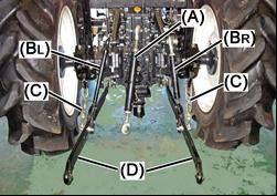
1. Install the lower link and the lift link.
(A) Top link: adjust leaning of the rotary backward or forward. (BL) Lift link, Left (BR) Lift link, Right: adjust tilting of the rotary right and left. (C) Check chain: adjust swing of the rotary right and left. (D) Lower link
IMPORTANT
Set correctly the lower link hole position and a lift link hole position. If it was not set correctly, following faults arise. - When moving the position control lever, the rotary may touch the tractor, or may damage the tractor and/or the rotary. - The drive shaft may cause noise or come off. The picture shows EF393T.
(A) Top link (BL) Lift link, Left (BR) Lift link, Right (C) Check chain (D) Lower link
Setting the lower ling and the lift link EF393T+RH170
Tractor model EF393T
Lower link hole position (a)
Lift link hole position [1]
Check chain hole position (b)
EF494T+RH190
Tractor model EF494T
Lower link hole position (b)
Lift link hole position [1]
Check chain hole position (d)
2. Adjust the length of the right lift link (BR) by turning the turnbuckle and make lower ling links (D) being the almost same height. EF393T
[A] Lift link [B] Lower link
EF494T
[A] Lift link [B] Lower link
4-2. Installing the top link
Install the top link to the top link hinge.
IMPORTANT
- When vibration occurs by wear of the pin and the hole, replace wear parts with new ones promptly.
Installing the top link
EF393T+RH170
Tractor model EF393T
Top link length [L] 590 mm
Top link hinge hole position [2]
EF494T+RH190
Tractor model EF494T
Top link length [L] 520 mm
Top link hinge hole position [2] EF393T
[C] Top link [D] top link hinge
EF493T
[C] Top link [D] top link hinge
4-3. Attaching/detaching the rotary
WARNING
- Never raise the rotary with installing only one side lift link. - Be sure to stop the engine whenever removing or installing the PTO drive shaft. It may cause an injury.
4-3-1. Attaching the rotary
1. Attaching order of the rotary to the tractor. 1) Attach the left lower link [A] to the rotary. 2) Attach the right lower link [B] to the rotary. 3) Attach the top link [C] to the rotary. 4) Connect the drive shaft [G].
[A] Lower link (left) [B] Lower link (right) [C] Top link [D] Lift link (left) [E] Lift link (right) [F] Check chain [G] Drive shaft
2. Connecting position of top link and lower link to the rotary
[1], [2] Lower link connecting position [3] Top link connecting position
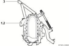
3. Connecting the drive shaft [G].
Push the lock pin [b] and put the drive shaft to the PTO shaft and the rotary pinion shaft.
[a] PTO shaft/Rotary pinion shaft [b] Lock pin [G] Drive shaft
IMPORTANT
- Check the lock pin is placed in the groove of the PTO shaft and the rotary pinion shaft.
When the pin is placed in the groove, the pin will return back.
4-3-2. Detaching the rotary
WARNING
- Be sure to stop the engine whenever removing or installing the PTO drive shaft[a]. It may cause an injury.
1. Put the tractor on a flat and hard place. 2. Set right and left skids [b] to the lowest position. 3. Lower the rotary till skids are on the ground. 4. Stop the engine.
5. Remove the drive shaft.
Push the lock pin and pull the drive shaft. Remove the rotary side first. 6. Pull out the pin of a top link and remove the top link. 7. Remove the right side lower link. 8. Remove the left side lower link. [b] Skid (right and left)
4-4. Adjusting the rotary
Adjust the rotary after attaching to the tractor.
1. Be sure that the PTO shift lever and the main gear shift lever is at the “N” (neutral) position. Be sure the parking brake is applied.
Start the engine. 2. Raise the rotary with the position control lever at a height of about 10 cm and stop the engine. 3. Make the rotary level (A) with the tractor by adjusting the right lift link [a].
4. Align the centerline of the rotary mast with the centerline of the tractor (B) by adjusting right and left check chains [b].
The free play (C) of right and left movement of the rotary is about 10 mm at the top link hitch pin or lower link hitch pin parts.
Be sure to insert the snap pin to the check chain after adjustment.
IMPORTANT
- Do not tighten check chains too much strongly. It may cause a breakage.
5. Start the engine and engage the PTO shift lever to the low speed. Raise and lower the rotary slowly with the position control lever and check a noise or vibration on the drive shaft or the rotary.
If noise and/or vibration occur, stop the engine and check hitching conditions of the rotary.
6. Adjust the height of skids for work.
4-5. Installing tilling blade
WARNING
- When installing or replacing tilling blades, put the tractor on a level and hard surface place, apply the parking brake and put chocks. If not, it may cause an injury accident. - When installing or replacing tilling blades, be sure close hydraulic stop valve fully to prevent from the rotary falling down. In addition to the hydraulic stop valve, put a support under the tilling blade shaft or skids for sure. If not, the rotary may fall down and may cause an injury.
Tilling blade installing (figure from the back side view)
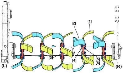
[1] Right tilling blade:
RH170/24 blades, RH190/27 blades [2] Left tilling blade:
RH170/24 blades, RH190/27 blades [3] Flange [4] Bolt M12x35, fine thread [5] Nut M12, fine thread [6] Spring washer M12 (L) Rotary left side (R) Rotary right side
Blade and bolt fixing (figure from the back side view)
[1] Right tilling blade [2] Left tilling blade
[3] Flange [4] bolt [5] Nut [6] Washer Bolt tightening torque: 98-128 N-m (10-13 kg-m)
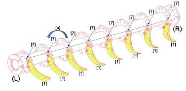
Tilling blade installing direction
The right figure is the view from the left side of the rotary. The small hole on the flange indicates the starting point of installing right tilling blade as the figure shows. Then, rotate the blade shaft in the direction [a] that the right figure shows, and install left tilling blade on the opposite side of right blade installing.
[a] The rotating direction of tilling blade shaft [b] The moving direction of the rotary [1] Right tilling blade [2] Left tilling blade [3] Flange [4] Bolt [5], [6] nut, washer [7] Small hole The figure from the left side view
[a] Rotating direction of tilling blade shaft (from the rotary left side view) [b] Moving direction of rotary (from the rotary lift side view)
Small hole is arranged as the under figure shows. The small hole indicates the starting point installing right tilling blade on the left side of the flange as the figure shows. Rotate the blade shaft in the direction of the arrow [a] and install left tilling blade on the right side of the flange. Then, install blade by alternating right and left blades. (The under figure shows RH170)
[a] Rotating direction of tilling blade shaft [1] Right tilling blade [7] Small blade (L) Left side of the rotary (R) Right side of the rotary