1 minute read
7.WIRING DIAGRAMS


7. WIRING DIAGRAMS
See Appendix B. at the back of this manual.
Color coding
R Red B Black W White L Blue RB Red/Black LB Blue/Black YW Yellow/White YB Yellow/Black YG Yellow/Green WL White/Blue WB White/Black WG White/Green GR Green/Red O Orange WBr White/Brown 1 Starter switch 2 Stop switch 3 Tachometer hour meter 4 Buzzer 5 Lubricating oil low pressure alarm 6 Coolant high temperature alarm 7 Water in sail drive seal alarm 8 Battery low charge alarm 9 Relay (for 2 station: Option) 10 Fuse (3A) 21 Glow plug 22 Engine stop solenoid 23 Stop relay 24 Starter relay 25 Starter 26 Coolant high temperature switch 27 Lubricating oil low pressure switch 29 Alternator 30 Water in sail drive seal sensor (on sail drive) 31 Water in sail drive seal drive only) sensor amplifier (Sail 33 Battery 34 Procured by customer 35 Battery switch 36 Earth bolt 37 Key switch 38 Only for sail drive 39 Wire harness. Option. 40 Instrument panel 41 Diodes 42 Alarm lamps
EN
53
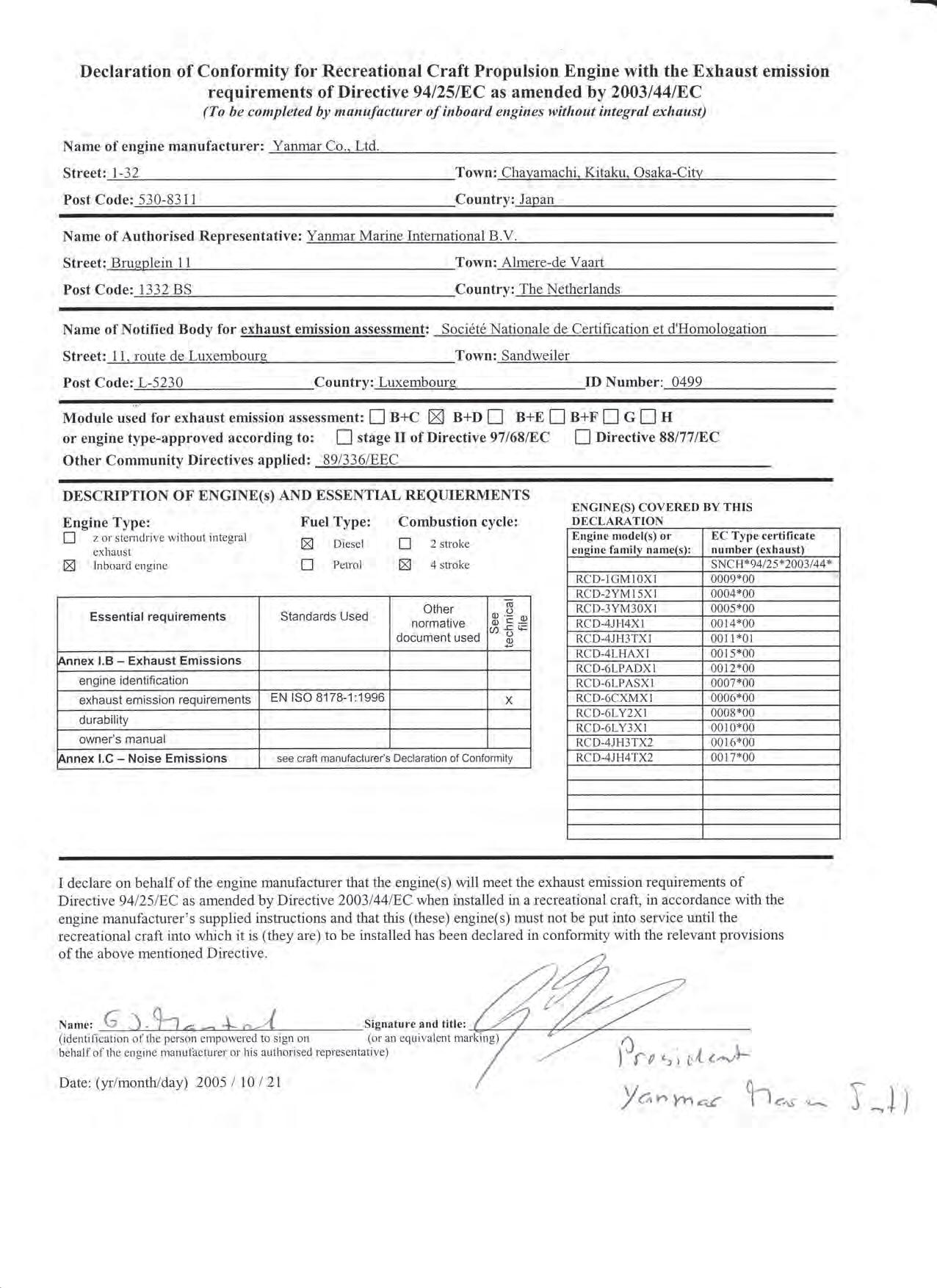
• MANUFACTURER’S DECLARATION FOR MACHINERY PARTS ACCORDING TO 94/25/EEC(ANNEX-15) & 89/336/EEC • MANUFACTURER: YANMAR CO., LTD. 1-32, Chayamachi, Kita-ku, Osaka, Japan
• DESCRIPTION OF THE MACHINERY PARTS • CATEGORY: Diesel engine 1. MAKE: YANMAR 2. THIS MACHINERY PART MUST NOT BE PUT INTO SERVICE UNTIL THE MACHINERY INTO WHICH IT IS TO BE INCORPORATED HAS BEEN DECLARED IN CONFORMITY WITH THE PROVISIONS OF THE DIRECTIVE. • IMPORTER IN THE EU: YANMAR MARINE INTERNATIONAL B.V. Brugplein 11 1332 BS Almere-de Vaart, The Netherlands
Nagahama, Japan, Sept. 21, 1997 Place and date issued Y. Sugita Manager Quality Assurance Dept. Power System Operation Div.
President, Yanmar Marine Int’l
President, Yanmar Marine Int’l