7 minute read
ASSEMBLY


DEALER SET-UP INSTRUCTIONS
Assembly of this mower is the responsibility of the Woods dealer. If should be delivered to the owner completely assembled, lubricated, and adjusted for normal cutting conditions.
Complete Dealer Check Lists on page 33 when you have completed the assembly.
The mower is shipped partially assembled. Assembly will be easier if components are aligned and loosely assembled before tightening hardware. Recommended torque values for hardware are located on page 46.
Select a suitable working area. Open parts boxes and lay out parts and hardware to make location easy. Refer to illustrations, accompanying text, parts lists and exploded view drawings. Front Offset Link Rear Offset Link
PTO Storage Bracket
Front Offset Link
Before working underneath, carefully read Oper-
ator’s Manual instructions, disconnect driveline, raise mower, securely block up all corners with jackstands, and check stability. Secure blocking prevents equipment from dropping due to hydraulic leak down, hydraulic system failures, or mechanical component failures.
Always wear relatively tight and belted clothing
to avoid getting caught in moving parts. Wear sturdy, rough-soled work shoes and protective equipment for eyes, hair, hands, hearing, and head; and respirator or filter mask where appropriate.
CAUTION
Uncrate Mower
1. Remove sides and top of mower shipping crate. 2. Remove lag screws and brackets that secure mower to crate base.
3. Remove driveshaft wired to mower deck.
Install Front Offset Links
1. Loosen lock nuts at lower hitch point and rotate offset link up off of gearbox as shown. 2. Tighten nut securely. 3. Repeat for opposite side. NOTE: Front link with the PTO storage bracket should be installed on right side of mower as shown in Figure 28.
Lock Nuts
Figure 28. Front Offset Links Installed
Install Rear Offset Links
1. Loosen nut (44) at rear frame lug and rotate offset link (9) up as shown in Figure 29. 2. Repeat for opposite side. 3. Do not tighten at this time.
9. Link, rear offset 44. Nut, flanged lock 1/2 NC Figure 29. Right Rear Offset Link Installed
44 9
CM905
9 44
40
11
10 30
CM757
CM757
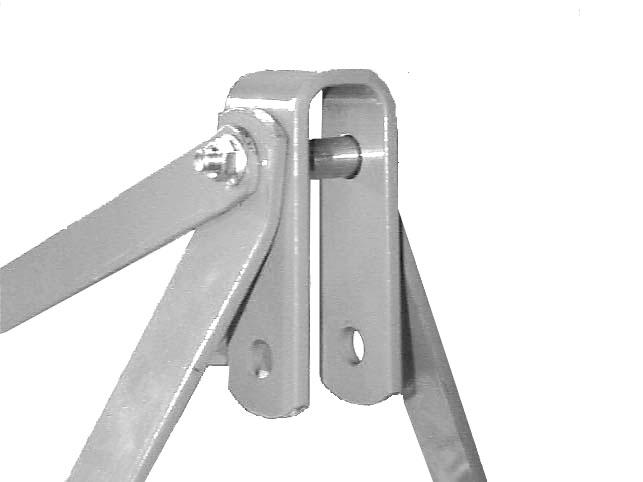
9.Link, rear offset 10.Link, front offset 11.Link, U-bracket 30.Sleeve, .62 x .84 x 2.88 40.Screw, HHCS 1/2 NC x 4-3/4 GR5 44.Nut, flanged lock 1/2 NC
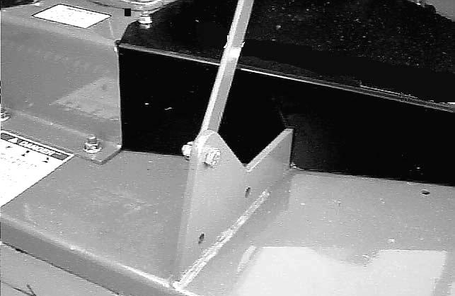
Figure 30. Top Link Assembled
1. Insert cap screw (40) through rear offset links (9), pipe (30), U-bracket (11) and front offset links (10) as shown and tighten securely with nut (44). 2. Tighten hardware on rear frame lug and offset link.
Install Rear Caster Arm

20
44 60
20.Caster arm assembly 44.Nut, flanged lock 1/2 NC 60.Screw, HHCS 1/2 NC x 1-3/4 GR5
Figure 31. Rear Caster Arm Installed 1. Remove rear caster wheel assembly (20) from shipping position and install as shown in Figure 31 using the same bolts (60) and nuts (44). 2. Repeat for opposite side. 3. Tighten bolts so that caster arm is snug against deck bracket, but not fully torqued.
NOTE: Refer to Front Caster Wheel Interference
Check, page 13 for possible front caster arm positions.
4. Attach front caster arm in desired position and tighten snug against deck bracket.

Torque Caster Arm Hardware
1. Lift mower off shipping pallet and set on a hard level surface. This allows clearance in the caster wheel assemblies to be equalized. 2. Tighten all cap screws and nuts on all four caster wheel arms.
3. Torque all cap screws and nuts to 85 lbs-ft.
Install Driveline Shield
Attach shield (2), Figure 32, to gearbox (1) with cap screws (5) and flat washers (4).
A.Gearbox input shaft B.Locking collar C.Anti-rotation chain 1.Gearbox 2.Shield 3.Driveline 4.Washer, flat standard 5/16 5.Screw, HHCS 8 mm x 1.25P x 16 mm
Figure 32. Rear Driveshaft Installation
Install Driveshaft
1. Pull locking collar (B) back and, at the same time, push driveline onto tractor gearbox shaft until locking device engages. 2. Attach shield anti-rotation chain (C) to drive shield (2) as shown.
NOTICE
■ Gearbox is not filled at the factory. Prior to
delivery, make sure each gearbox is filled half-full with 80W or 90W API GL-4 or GL-5 gear lube.
1. Make sure vent plug hole is clear. Fill gearbox halffull with high quality gear oil that has a viscosity index of 80W or 90W and an API service rating of
GL-4 or GL-5. 2. Fill gearbox until oil runs out the side plug on gearbox. 3. Pour in one pint of gear lube, wait five minutes and add additional gear lube until it just comes out of side hole. 4. Allow an additional five minutes for the lube to flow through bearings, then check to make sure oil level is at bottom of side hole. Replace side plug. Install vent plug.
Install Chain Shielding (Optional)
Full chain shielding must be installed when
operating in populated areas or other areas where thrown objects could injure people or damage property. •If this machine is not equipped with full chain shielding, operation must be stopped when anyone comes within 300 feet (92 m). •This shielding is designed to reduce the risk of thrown objects. The mower deck and protective devices cannot prevent all objects from escaping the blade enclosure in every mowing condition. It is possible for objects to ricochet and escape, traveling as much as 300 feet (92 m).

15
14
3

CM768
3.Shield, chain plate 14.Bolt, carriage 3/8 NC x 1 15.Nut, flanged lock 3/8 NC Figure 33. Chain Shield Installed 1. Install chain shielding plate (3) to rear mower frame as shown. 2. Secure with carriage bolts (14) and flanged lock nuts (15).
Insert carriage bolts from bottom upward as shown.
Install Front Roller (Optional)
1. Insert four carriage bolts (5) through the front mower frame from inside out. 2. Place roller bracket (8) over bolts; then install flange whiz nuts (6) on bolts and tighten. 3. Place front roller (9), two bearings (10), spacer (7) and two SAE flat washers (4) between roller bracket as shown in Figure 34. 4. Insert cap screw (3) through bracket and roller. 5. Secure with flanged lock nut (2). Do not overtighten, roller must spin freely.
2. 1/2 NC Flanged lock nut 3. 1/2 NC Flanged lock nut 4. 1/2 SAE Flat washer 5. 3/8 NC x 1 Carriage bolt 6. 3/8 NC Flanged whiz nut 7. Spacer, .75 x 6.62 8. Bracket, front roller 9. Roller, 4 x 7.37 10. Bearing
Figure 34. Front Roller Installation
Install Quick Hitch Kit (Optional)
NOTE: This kit allows mower to fit only Category 1 standard quick hitch. 1. Make sure that you are using one of the front two attachment points (D) in the lower hitch plates. See
Figure 6, page 12, for adjustment. 2. Remove clevis pins from lower hitch arms. The pins will not be used for the Quick Hitch.
CHAIN CUT-TO-LENGTH CHART
Model Dimension “A”
PRD6000 40" PRD7200 45" PRD8400 50"
NOTE: This kit is used on other models. Use only the hardware listed below.

1.Offset link, .38 x 2 x 15" 2.Chain, 3/8 proof coil 38-link 3.Sleeve, .94 x 1.44 x 1.94" 4.Screw, 1/2 NC x 6 HHCS GR5 5.Washer, 1/2" flat 6.Sleeve, .50 x .75 x 3.38"
7.Nut, 1/2 NC flange lock 8.Sleeve, 7/8 x 1-1/8 x 19/32" HT 9.Washer, 3/4 flat 10.Sleeve, .81 x 1.25 x 1.81" 11.Screw, 3/4 NC x 4-1/2 HHCS 12.Nut, 3/4 NC plated hex
Figure 35. Quick Hitch Kit Installation (Optional)
3. Attach offset link (1) to lower hitch clevis using sleeves (3 & 8), two flat washers (9), cap screw (11), and hex nut (12) as shown in Figure 35. Do not tighten hardware. Repeat for opposite side.
4. Attach upper end of offset links (1) to each side of
U-bracket link, using two flat washers (5), sleeves (6 & 10), flange lock nut (7), and 1/2 x 4-3/4 cap screw.
5. Remove rear offset links. They will be replaced with chains (2) 6. Attach chains to top of A-frame on both sides as shown, using cap screw (4), two flat washers (5), and nut.
7. Attach opposite ends of chains (2) to rear mower frame as shown. Cut chains to length (see chart above). Vary length slightly as desired. Twist chain to make finite adjustments in length until unit lifts level.
8. Tighten all hardware.