7 minute read
OWNER SERVICE


The information in this section is written for operators who possess basic mechanical skills. If you need help, your dealer has trained service technicians available. For your protection, read and follow the safety information in this manual.
Never allow children or untrained persons to
operate equipment.
Keep bystanders away from equipment. Before working underneath, carefully read Oper-
ator’s Manual instructions, disconnect driveline, raise mower, securely block up all corners with jackstands, and check stability. Secure blocking prevents equipment from dropping due to hydraulic leak down, hydraulic system failures, or mechanical component failures.
Keep all persons away from operator control
area while performing adjustments, service, or maintenance.
Operate tractor PTO at 540 RPM. Do not exceed.
Always wear relatively tight and belted clothing
to avoid getting caught in moving parts. Wear sturdy, rough-soled work shoes and protective equipment for eyes, hair, hands, hearing, and head; and respirator or filter mask where appropriate.
CAUTION
BLOCKING METHOD
Do not work underneath mower unless it is properly attached to the tractor and blocked securely. When properly attached, the unit will be anchored to minimize front to rear movement.
Raise mower completely, set tractor brakes, turn engine off, remove key, block tractor wheels front and rear, and disconnect mower driveline from tractor.
The only approved blocking device for this mower is a jackstand with a load rating of 1000 pounds or more. One jackstand under each corner of the mower (four total) must be installed before working underneath. When blocking, you must consider overall stability of the unit. Just blocking under the unit will not ensure your safety. The working surface must be level and solid to support the loaded weight of the jackstands. Test jackstands stability before working under any portion of the mower. Figure 11. Blocking Method
LUBRICATION INFORMATION
Do not let excess grease collect on or around parts, particularly when operating in sandy areas. Figure 12 shows the lubrication points. The accompanying chart gives the frequency of lubrication in operating hours, based on normal operating conditions. Severe or unusual conditions may require more frequent lubrication. Some reference numbers have more than one location; be sure you lubricate all locations. Use a lithium grease of #2 consistency with a MOLY (molybdenum disulfide) additive for all locations. Be sure to clean fittings thoroughly before attaching grease gun. When applied according to the lubrication chart, one good pump of most guns is sufficient. Fill blade spindles until grease purges out of the upper seal. Use SAE 90W gear lube in the gearbox. Fill to plug on side of gearbox. Check gearbox daily for evidence of leakage at both seals and the gasket between the housing and cover. If leakage is noted, repair immediately. There may be a small amount of lube emitted from the vent plug; this is not considered leakage. Overfilling the gearbox will cause the excess gear lube to blow out vent plug and ruin the belt.
Driveshaft Lubrication
Lubricate the driveshaft slip joint every 8 operating hours. Failure to maintain proper lubrication could result in damage to U-joints, gearbox, and driveshaft. 1. Lower mower to ground. 2. Apply grease at three locations shown in Figure 12. 3. Raise and lower mower several times to distribute grease.

REF DESCRIPTION FREQUENCY
1 Front U-Joint 8 Hours 2 Caster Wheel (Four wheels) 8 Hours 3 Caster Pivot (Four wheels) 8 Hours 4 Left Spindle (Access through hole) 24 Hours 5 Shield Bearings 8 Hours 6 Rear U-Joint 8 Hours 7 Gearbox (Fill to center of horizontal shaft with SAE 90W gear lube) Check Daily 8 Right Spindle (Access through hole) 24 Hours 9 Center Spindle (Access through hole) 24 Hours 10 Slip Joints 8 Hours
Figure 12. Lubrication Points & Chart
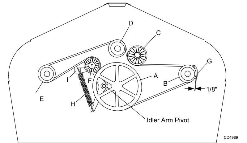
Figure 13. Belt Routing
BELT SERVICE Belt Replacement
One of the major causes of belt failure is improper installation. Before installing a new belt, check the following:
1. Check pulley shafts and bearings for wear. 2. Check pulley grooves for cleanliness. 3. Make sure spindles turn freely and without wobble.
If grooves require cleaning, moisten a cloth with a nonflammable, non-toxic degreasing agent or commercial detergent and water.
Avoid excessive force during installation. Do not use tools to pry belt into pulley groove. Do not roll belt over pulleys to install. This can cause hidden damage and premature belt failure.
Belt Installation
1. Disconnect idler spring from deck lug I. 2. Slide belt under drive pulley A and over idler arm.
Position belt around drive pulley A. 3. Loosen bolt holding belt guide G and swing it away from pulley B. Route belt around pulley B, idler C and pulley D as shown. 4. Make sure belt is on drive pulley A, route around idler F, and connect idler spring to lug I on deck. 5. Grasp belt between spindle pulley E, spring loaded idler F and spindle pulley D. Pull spring loaded idler with belt to obtain enough belt length to route it over pulley E. Make sure spring-loaded idler pivots freely with belt installed.
NOTICE
■ Use care when installing or removing belt from
spring-loaded idler at step 5. Springs store energy when extended and, if released suddenly, can cause personal injury.
6. Adjust belt guide G to provide 1/16" to 1/8" clearance from belt. Tighten bolt to 85 lbs-ft.
BLADE SERVICE
Before dismounting power unit or performing
any service or maintenance, follow these steps: disengage power to equipment, lower the 3-point hitch and all raised components to the ground, operate valve levers to release any hydraulic pressure, set parking brake, stop engine, remove key, and unfasten seat belt.
Keep all persons away from operator control
area while performing adjustments, service, or maintenance.
CAUTION
Your dealer can supply genuine replacement blades. Substitute blades may not meet original equipment specifications and may be dangerous.
1.Spindle assembly 2.Blade 3.1/2 NC x 1-1/2 HHCS GR5 4.1/2 NC Flange lock nut Figure 14. Blade Assembly 1. Place cap screws (3) through outer holes in blade and spindle shaft. 2. Make sure blade cutting edge is positioned to lead in a clockwise rotation, as viewed from top of mower. 3. Place locknuts (4) on screws, torque to 84 lbs-ft.

Blade Sharpening

Figure 15. Blade Sharpening NOTICE
■ When sharpening blades, be sure to balance
them. Unbalanced blades will cause excessive vibration which can damage blade spindle bearings. Vibration may also cause structural cracks in mower components.
1. Remove blades. 2. Always sharpen both ends at the same time to maintain balance. 3. Follow original sharpening pattern. 4. Do not sharpen blade to a razor edge. Leave from 1/32" to 1/16" blunt edge. 5. Do not sharpen back side.
CHAIN SHIELDING
Full chain shielding must be installed when
operating in populated areas or other areas where thrown objects could injure people or damage property. •If this machine is not equipped with full chain shielding, operation must be stopped when anyone comes within 300 feet (92 m). •This shielding is designed to reduce the risk of thrown objects. The mower deck and protective devices cannot prevent all objects from escaping the blade enclosure in every mowing condition. It is possible for objects to ricochet and escape, traveling as much as 300 feet (92 m).
Check that chain shielding is in good condition and replace any damaged chain links.
CLEANING
After Each Use
● Remove large debris such as clumps of dirt, grass, crop residue, etc. from machine. ● Inspect machine and replace worn or damaged parts. ● Replace any safety decals that are missing or not readable.
Periodically or Before Extended Storage
● Clean large debris such as clumps of dirt, grass, crop residue, etc. from machine. ● Remove the remainder using a low-pressure water spray. 1. Be careful when spraying near scratched or torn safety decals or near edges of decals as water spray can peel decal off surface. 2. Be careful when spraying near chipped or scratched paint as water spray can lift paint. 3. If a pressure washer is used, follow the advice of the pressure washer manufacturer. ● Inspect machine and replace worn or damaged parts. ● Sand down scratches and the edges of areas of missing paint and coat with Woods spray paint of matching color (purchase from your Woods dealer). ● Replace any safety decals that are missing or not readable (supplied free by your Woods dealer).
See Safety Decals section for location drawing.