7 minute read
Guideline for laser line-bore measurements


Wärtsilä NSD Nederland B.V. Engine type W26 Chapter 2.5 Subject
Issue date Engine block/Cylinder liner June '00
Guideline for laser line-bore measurements
Required measuring equipment
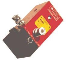
Laser transmitter (for example transmitter : Fixtur Digilaser FL11 or Damalini Easy Laser D75)+ special designed bracket (not shown)
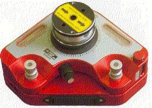
Laser detector (for example Digilaser D11 or Easy Laser D5) +. Machine
Support line-bore bracket
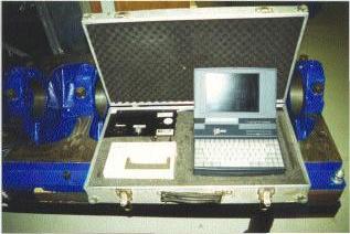
Display box for signal read out :consisting of laser signal convertor + cables (for example Digilaser display box incl. Adcom or Easy Laser display box).
Laser transmitter for flatness check (for example Digilaser FL100 or Easy Laser D22 ).

Wärtsilä NSD Nederland B.V. Engine type W26 Chapter 2.5 Subject
Issue date Engine block/Cylinder liner June '00
Notes: The used laser detector should match with the display box. The resolution of the Adcom should be set on 0,01 mm. Use the following filter settings for the Diglaser Adcom or Easy laser:
Engine shorter then 3000 mm – 6 seconds.
Engine length larger than 3000mm - 12 seconds. Enter the real distance between the centre of the main bearing pockets (±5 mm) into the
Adcom. (for W26 distance = 390 mm) X+ side of the detector should match the 2x2 legs bottom side of the bracket. Before measuring, switch on the laser transmitter. Allow the equipment to acclimatise to site temperature with a minimum of 15 minutes. Make sure that the lens of transmitter and detector are and stay clean. Wait 5 seconds before every measurement after placing the detector bracket and in case the Adcom is used the log scale on the computer should be below 60% of the scale.
Preparation: 1) Make a measurement protocol of the (new) bearing caps (size F;G) (See Measurement record, mr26/1301/02) 2) Make a protocol of the engine block bearing caps rebate width D; E (See Measurement record, mr26/1301/02) 3) Mount all main bearing caps (renewed if necessary) without bearing shells according the procedure as mentioned in the engine manual. 4) Make a measurement protocol ( a,b,c; a1,b1,c1 ) of all main-bores. (See Measurement record, mr26/1301/01) 5) Place the engine-block feet on six points (the engine block should be supported in the middle) in one horizontal plane preferable on adjustable chocks (e.g. vibracons; size SM 16) or by means of jack bolts. 6) Check the flatness of the horizontal plane of the engine-block feet by laser on six points (use for this a magnetic bracket on a cleaned surface), so there is no twist or bending in the engine block. A tolerance of 0.05 mm is allowed.
Checking the (main bearing) line bore: 7) Clean all the main bearing pockets with a cloth from dirt ,oil etc.
Note: use no degreasing agent like thinner! 8) Eliminate or remove as far as possible any vibrations, moving air and heat sources
near the measuring site as these will disturb the measurements.
9) Record all applicable data like: date, temperature, relation engine bearing pocket no. / measurement no. , direction of + for x / y , position eng. block, measurement before / after machining, damaged bearing pocket no,line-bored bearing pockets no’s, and the oversize of bearing pocket(s), serial no’s of the used measuring equipment. (see mr26/1301/01, mr26/1301/02, mr26/1301/03) 10) Mount the laser transmitter preferable rigidly to the engine block (on a rigid bracket) between 250 and 1000 mm distance of the first bearing pocket. (This to prevent reflection of the laser)
Wärtsilä NSD Nederland B.V. Engine type W26 Chapter 2.5 Subject
Issue date Engine block/Cylinder liner June '00
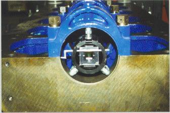
11) Adjust the laser detector bracket with the help of a measuring tape in the centre of the first and last pocket. 12) Fix the bracket to the right diameter of the bore (tolerance 1 mm) 13) Put the laser detector in the first pocket (seen from laser transmitter) with the bracket 2x2 legs down. The pointer should point to the split line of the bearing bore. Set the display box or Adcom to zero. 14) Turn the laser detector bracket upside down. The pointer should point to the split line of the bearing bore. Divide the readings on the display box or Adcom by two. 15) Adjust the laser transmitter bracket in radial position till the reading on the display box is zero in X and Y direction. 16) Turn the laser detector bracket in the starting position ( 2x2 legs of bracket down) and check if the reading on the display box or Adcom is still zero or very near ( 0.02 mm). 17) Put the laser detector bracket in the last pocket (seen from laser transmitter) and adjust the angle of the laser beam by using the micrometer screws on the laser transmitter.
Check the stability of the laser transmitter by slightly pushing it. Depending on the distance between the laser transmitter and laser detector it should not move more then approx. 0.1mm, and it should return afterwards to zero. 18) Repeat step 13 -17 until the laser beam has reached an accuracy of 0.03 mm or better to the centre of the bore. 19) Check the line bore of the engine block, start in the last pocket (seen from laser transmitter).
Position the laser detector bracket (make sure the laser detector bracket is in an upright position, the pointer should point to the split line of the bearing bore)
Work to the first pocket and check each pocket by checking the reading on the display box.
Note : if the laser detector bracket is mis-positioned, the reading on the display box will be larger then 0.1 mm.
In that case take out the laser detector and re-position it.
Work quickly but accurate (< 1 min. per position) 20) Rename the measured bearing numbers.
Note : W26 pocket 0 is the first pocket on flywheel side. 21) Print out the line-bore report. 22) Repeat step 19 - 21. 23) Compare the two reports. A difference of 0.01 mm in 40% of all readings is allowable for engines shorter then 5000 mm. For larger engines this accuracy could be 0.02 mm if the measurement is done in field conditions. If there are more readings out of tolerance, repeat step 19 - 21.
If there is again a difference larger then the tolerance, recheck all the equipment for failures and repeat the measurement one more time. 24) Determine the resultant of the measured X and Y value. (see mr26/1301/03)
Determine the eccentricity of the main bearing line-bore over groups of three bores at a time. {(resultant left bore + right bore) / 2 – resultant middle bore}
Note : the circular run-out is two times the eccentricity. (see mr26/1301/03)
Compare the circular run-out with the no-go figure.
Wärtsilä NSD Nederland B.V. Engine type W26 Chapter 2.5 Subject
Issue date Engine block/Cylinder liner June '00
25) If necessary line bore one or more bores, check (if possible) after pre-machining and before final machining the new bore position by laser, see tolerances below.
Note ; When measuring an oversized bearing pocket a correction should be calculated because of the fact that the detector bracket legs (2x2) are positioned under an angle, or otherwise the detector bracket should be turned before the measurement over 180 degrees, so that the vertical movement can be measured directly. 26) Check after line-boring the line bore again by laser and make protocol. (see mr26/1301/03) Note ; see note at point 25. 27) Make a measurement protocol (a,b,c; a1,b1,c1) of the line bored pocket(s) (without and with bearing). (See Measurement record mr26/1301/01) 28) Check crankshaft deflections and alignment before and after tightening the foundation bolts, and make protocols (see mr26/1301/01 and mr26/1111/01) 29) Check during running-in all bearing temperatures (after max. 5 min and after full load), and do a visual bearing / crankcase inspection, (see also chapter 2.3) 30) Check after running-in the paper element of the lub.oil filters on wear / bearing / dirt particles, and renew the lub.oil filters.
Note :
Technical Service WNSNL-S has developed a calculation program to judge the results before and after the line bore job. It is recommended to send the results of the laser line bore measurements together with measurements of all pockets to the Technical Service for approval and advice.
