
15 minute read
Cylinder head, change


Current cut. Drained cooling system and sea water.
Removal
1. Remove the cover and the fuel filter bracket.
2. Undo the sea water hoses and all the intercooler hose connections to inlet and turbo pipes.
3. Remove the electric connector (1) on the intercooler, together with the dipstick bracket (2).
4. Remove the intercooler, 4 screws, and the mounting bracket.
Remove the reverse gearbox oil cooler.
5. Undo the cables on the starter motor.
Unscrew the starter motor (1), note the guide pin (2).
1
2

6. Remove the expansion tank and its bracket, air filter, vacuum hose, turbo pipe and coolant hose.
Remove the exhaust elbow and the hose for the heat exchanger.
7. Remove the hose anchorage (1) on the thermostat housing and the inner hose connection (2) on the thermostat housing.
8. Remove the oil pipes and the heat exchanger, then remove the manifold together with turbocharger.


9. Undo the connectors for the injectors, and put the cable harness to one side.
10.Remove the cam belt, please refer to “Cam belt, change” under “service work”.
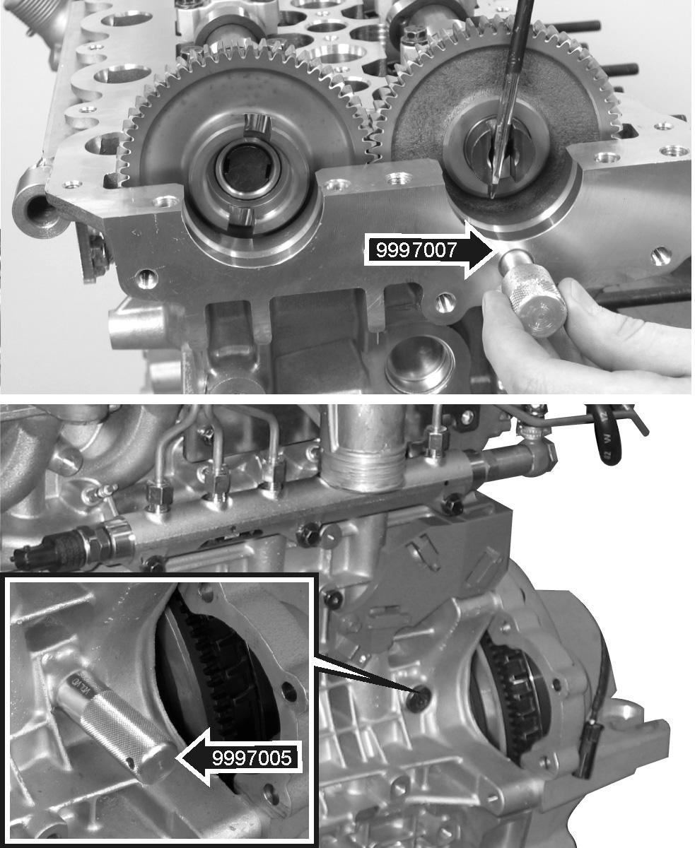
11.Put the lock pin 9997007 into the hole under the exhaust camshaft.
Unscrew the plug on the engine block behind the starter motor position. Install lock pin 9997005 and make sure it bottoms against the block. Also refer to “Crankshaft, locking”.

12.Remove the camshaft gear (1), jockey pulley (2) and belt tensioner (3).
Remove the rear cover.
13.Remove the fuel injector pipes and the injectors.
14.Undo the hose from the crankcase ventilation to the valve cover.
Remove the valve cover.
15.Remove the rear camshaft bearing caps and remove the camshaft locking pin 9997007.
Remove the front seal retention cap (2).
Undo the screws for all camshaft bearing caps (1), working from the outside towards the center.
IMPORTANT! Undo each screw one turn at a time until the camshafts longer spring upwards.
Remove the screws, bearing caps and camshafts.
IMPORTANT! Put the bearing caps and camshafts on a clean, dry surface. The bearing caps are marked and must be re-installed in the same places. If the bearing caps are wrongly installed, this can cause engine failure.


17.Pull all hydraulic valve lifters (1) up out of the cylinder head. NOTE! The valve lifters might come to pieces, but are easy to re-assemble.
IMPORTANT! Mark the valve lifters and store them in a vessel containing clean engine oil until they are installed.
WARNING! The cylinder head has very sharp edges. Be careful when working with it.
18.Undo the cylinder head screws. Start to undo them, working from the outside towards the center.
Undo the cylinder head and put it on a clean, dry, soft surface. NOTE! Save the gasket or note its marking, please refer to “Engine, assembly, cylinder head”.
IMPORTANT! The gasket plane and the plugs beside the valve heads must not be damaged. The gasket is basically unable to seal a scratch or other damage to the sealing plane.
Installation
19.Put a new gasket (1) on the engine block. Make sure that a gasket of the correct thickness is used. This is indicated by a combination of holes (2) on the edge of the gasket, please refer to “Cylinder head gasket, measurement”.


20.Move no. 1 piston to Top Dead Center. Make sure that lock pin no. 9997005, for locking the crankshaft, bottoms against the block.
Turn the crankshaft counter-clockwise until the crankshaft counterweight rests against the lock pin. No. 1 piston (1) is now about 2 mm before
Top Dead Center.
The crankshaft is now in the correct position, which can also be checked on the crankshaft’s toothed belt pulley (2) and the oil pump marking (3).
Also refer to “Crankshaft, locking”.
21.Oil all the cylinder head screws with engine oil and leave them to drain on paper for about 10 minutes.
Put cylinder head in place and install the screws lightly (1-12) by hand.
Torque the screws alternately, from the center and out, as specified in “Technical data”.
IMPORTANT! Use the greatest care during assembly, to avoid damaging the gasket plane and the plugs by the valve heads.
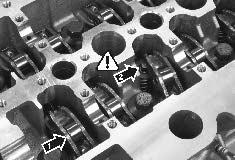
22.Oil the valve lifters (1) and install them in the order they were marked. NOTE! Check that the valve lifters are in contact with the valve stems. The illustration shows a valve lifter (2) in the wrong position.

23.Check that all the bearing surfaces on the camshafts, camshaft bearing caps and cylinder head have been carefully cleaned.
Lubricate the following: - Camshaft bearing surfaces and lobes - Cylinder head bearing surfaces - Camshaft bearing caps - Valve lifter rollers
Install the camshafts with markings (1) on the camshaft drive gears facing each other.
24.Install all camshaft bearing caps (A) as marked, except the front bearing cap (B) on the inlet camshaft. Tighten the screws until the bearing caps touch the camshafts. NOTE! The bearing caps are marked “I” (Inlet) and “E” (Exhaust), and numbered 1-6 to facilitate assembly.
Carefully tighten the screws for caps 1-6 alternately, working from the center and outwards, one turn at a time, until the camshafts are fixed against the cylinder head.
Torque the screws as in the specification in
“Technical data”.
IMPORTANT! Make sure that the camshafts do not rotate during installation of the bearing caps.
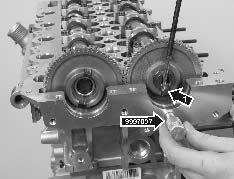
25.Put locking pin no. 9997007 in the cutout for the exhaust camshaft. Carefully turn the camshafts with a screwdriver in the high pressure or vacuum pump grooves (1) to facilitate installation of the lock pin.
IMPORTANT! The camshafts must not be turned more than needed to install the lock pin. There is a risk that the valves could be damaged.
26.Clean the front and rear bearing caps.
Apply liquid gasket 1161059-9, using roller no. 885511 on the gasket plane (1). The surface should be completely covered, without surplus.
Grease bearing race (2) on the front bearing caps.
Install the caps and torque the M10 and M6 screws to the values specified on the torque table in the “Technical Data”.
27.Install the inlet camshaft seal ring (1). Use tool no. 9997006 to press the seal ring in until the tool bottoms against the camshaft.
IMPORTANT! The seal ring dust lip will be damaged if it is stretched. If it has been incorrectly aligned or has been forced in, it must be changed.


28.Install the shaft with butterfly. Press the rubber seal down all the way.
Install the rubber tape inside the control arm.
Install the lock washer (1) so that the butterfly (2) remains open.
Scrape the valve housing seal surfaces clean and wipe them off.
Check that the camshaft lobes are fully covered with an oil film, lubricate if necessary.
Press the valve cover gasket into the groove in the valve cover.
29.Carefully put on the valve housing/inlet pipe without disturbing the position of the gasket during assembly.
Torque the valve cover screws alternately as specified in “Technical data”.
30.Clean the injector’s nozzle seats using brush 885289.
IMPORTANT! Make sure that the surface where the injectors reach the lower part against the cylinder head are thoroughly cleaned. No deposits are allowed.
Make sure that the tool end of the brush has been carefully cleaned. Use compressed air to blow the nozzle seat clean. Turn the brush a few times with the rod until the nozzle seat surface is completely free from soot. Blow clean from time to time and check cleanliness.
31. Refitting of injectors and delivery pipes
Fit the injectors and screw new tension braces down so much that the injectors still can be rotated slightly.
Use tool 999 7010 to place the injectors in the correct position. Torque the screws to 13 Nm.
IMPORTANT! When installing new or old injectors, you must use new tension yokes, spacers, lock rings, copper washers and screws.
32.Fit the new delivery pipes. Screw all cap nuts all the way down by hand.
33.Install the rear timing gear cover (1). Check that it comes into the correct groove (2) behind the coolant pump.
Install the lower belt guard.
34.Install the toothed belt jockey pulley (1). Torque the screw as in the specification in “Technical data”.
Screw the belt tensioner (2) down. Undo the center screw about one turn and turn the eccentric washer (3) with a 6 mm Allen key until it is in the position shown in the illustration. It is easiest to install the toothed belt in this position.


35.Fix the camshaft toothed belt pulley with one of the three screws (1). Check through the open screw hole (2) that the screws are not in their end positions in the elongated holes (3) on the toothed belt pulley. If the screws are in their end position, it may be impossible to tension the toothed belt.
Make sure that the marking on the pulley (4) and the timing gear cover (5) line up.
Loosen the screws until the pulley can slide in the elongated screw holes.
36.Install the toothed belts in the following order: 1. Crankshaft 2. Jockey pulley 3. Camshaft gear 4. Belt tensioner 5. Circulation pump
IMPORTANT! The toothed belts must be kept taut during installation.
NOTE! Also observe the replacement interval for toothed belts, please refer to “Technical data, Engine body”.


37.Set the belt tensioner to the tensioned position (1). Then tighten the screws (2). No fine adjustment is necessary at this point. The illustration shows the position of the belt tensioner at various temperatures of the engine block.
Check that lock pins 9997007 for the exhaust camshaft and 9997005 for the crankshaft are in place, please refer to “Crankshaft, locking”.
38.Check that the open screw hole (1) is not in the end position in relation to the elongated hole. If the screws are in their end position, it will not be possible to tension the toothed belt correctly.
Tension the toothed belt in the direction of the arrow, using counterhold 9995199 and fix the camshaft pulley with the three screws. Torque the screws as specified in “Technical data.”
Fit the last screw and torque as specified in
“Technical data.”
IMPORTANT! Make sure that the toothed belts are taut between the crankshaft, jockey wheel and camshaft pulley during tightening.
39.Apply pressure (1) to the toothed belts and check that the belt tensioner (2) moves. NOTE! The belt tensioner must be changed if it does not move.


40.Remove locking pins 9997005 and 9997007 and install the plug in the block.
Set the belt tensioner in relation to the temperature of the engine block, please refer to the figure.
Torque the belt tensioner as specified in “Technical data”. NOTE! The illustration shows the temperature of the engine block when the belt tensioner is set up.
41.Turn the crankshaft round two rotations. Check the marking on the crankshaft pulley (1) and the marking on the camshaft pulley (2).
Check that the belt tensioner indicator (3) is within the marked temperature range. If necessary, adjust as above.
IMPORTANT! Check that the engine can be cranked without any unwanted noise or complications.
Install the front timing gear cover.
42.Apply a tool with a T60 Torx bit (1) to the cutout in the belt tensioner. Turn the belt tensioner (2) and insert a screwdriver (3) or similar into the hole which opens up and secure the belt tensioner.
Install the drive belt (4) and then release the locking of the belt tensioner. NOTE! Make sure that the drive belt has not slid out of its grooves.


43.Install new O-rings (1) on the vacuum pump. Make sure that flange (2) enters the exhaust camshaft.
Torque the screws as specified in “Technical data.” NOTE! Handle the vacuum pump carefully. A vacuum pump which has been dropped or damaged in any other way must not be re-installed under any circumstances.
44.Install a new O-ring (1) on the high pressure pump and install it together with its flange (2).
Screw the high pressure pump down as specified in “Technical data.”
45.Install the fuel return pipe and join up the electric connector.
46.Angle tightening of cap nuts
IMPORTANT! When torquing nuts to 40° - 60° angle, a torque wrench must be used, adjusted to 45 Nm. It is important that you do not exceed 45 Nm.
IMPORTANT! If the torque becomes too great before reaching the correct angle, the connection must be removed and lubricated with engine oil before it is torqued again. If the torque again exceeds 45 Nm, the delivery pipes must be replaced with new ones.
The nut is hexagonal and each corner is 60°.
Mark the pipe and one side of the nut using a pen as illustrated. The side of the nut is divided into three equal parts, which correspond to 20° each. NOTE! The mark should not be made until the nut has been torqued to 28 Nm.
When the line on the pipe faces the right section, the torque angle will be between 40° and 60°.

12 11 10 9 8
47.Torquing cap nuts
Torque all cap nuts (1-12) to 28 Nm.
Set torque wrench to 45 Nm and torque the cap nuts (1-7) to 40° - 60° angle. NOTE! Do not torque the cap nuts (8-12) using angle tightening.
Tightening torque must not exceed 45 Nm.
48.Join up the injector connectors.
49. NOTE! Check that the crankshaft lock has been removed and the plug is installed.
Install the starter motor and screw it in place.
Note the guide pin (1). Install the long screw first, furthest down and install the earth (ground) cable on it.
50.Install the manifold with a new gasket, tighten the 4 nuts as in the illustration.
Install the hoses and anchorage on the thermostat housing, together with the turbo pipe, vacuum hose, air filter and coolant hose.
7 6 5
4
3 2
1


51.Install the heat exchanger. Loosely tighten the nuts and screws. NOTE! The screws (1) must have a washer on each side of the heat exchanger.
52.Install the oil pipes on the turbocharger (1) and the engine block loosely.
Install the oil return pipe (2) on the turbo, and secure it with the bracket on the engine block.
Tighten the screws loosely. NOTE! The hollow screw leading in to the turbo should have a restriction. Use a new gasket and copper washers.
53.Install the bracket for the expansion tank.
Torque all the nuts on the exhaust manifold, except the one that holds the bracket for the exhaust bend (2), to 20 Nm.
Torque the heat exchanger screws (3) to 25 Nm.
Torque the turbo oil drain pipe (4), hollow screw (5) for the oil supply pipe to the turbo and the hollow screw (6) to the engine block, to the values specified in “Technical Data”.


54.Install a new gasket with the swage facing outwards, and install the exhaust pipe elbow (1). Use new nuts (2) and torque them to 30 Nm. NOTE! An anchorage (3)+ for the manifold is fixed to the lower nut.

55.Install the expansion tank on its bracket. NOTE! Do not forget the spacer tube for the fixing screw.
56.Screw the intercooler bracket (2) in place. NOTE! Apply Volvo Penta sealant part. no. 840879-1 to the threads of the two lowest screws (3).
1
2
3
57.Install the intercooler on the bracket. Insert the short hose (1) between the induction manifold and the intercooler before the screws are tightened.
Join up the connector for the intercooler sensor (2) and tighten the dipstick clamp (3) to the intercooler. NOTE! Install the fuel return hose on one of the intercooler screws.
IMPORTANT! Make sure that the hoses are installed so they do not chafe against anything.
58.Install the oil cooler (servo) or joining pipe.
Install the air filter housing (1) on the turbocharger.
Connect the turbocharger vacuum hose and crankcase ventilation (2).
Install the charge air pipe (3) between the turbocharger and the intercooler. 59.Install all coolant hoses (4) to the sea water pump, intercooler, heat exchanger, exhaust pipe elbow, exhaust manifold, expansion tank, oil coolers, thermostat housing and coolant pipes.
60.Screw the fuel filter housing (1) in place. Connect the fuel pipe (2) between the high pressure pump and the fuel filter housing.
Install a new fuel filter (3).
Install the oil cooler (servo) bracket (4) or joining pipe to the bracket under the intercooler.
Install new tie wraps on the cables and hoses, as previously noted.

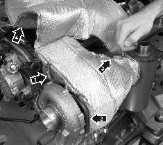
61.Insert the spring (1) from underneath between the turbocharger exhaust turbine and the vacuum capsule bracket. Hook the spring on. Make sure that the heat shield (2) goes in between the oil pipe and the exhaust turbine.
Fix the row of hooks (3) with the steel wire.
Fold over the rest (4) of the heat shield and fix the remaining rows of hooks with steel wire.
Join the sea water hose up to the exhaust pipe elbow.
IMPORTANT! Check that the heat shield or spring (1) do not obstruct the vacuum capsule control arm.


