
3 minute read
Cylinder head


18. Cylinder head
Put a new gasket (1) on the engine block. Make sure that a gasket of the correct thickness is used. This is indicated by a combination of holes (2) on the edge of the gasket, please refer to “Cylinder head gasket, measurement”.
19.Move no. 1 piston to Top Dead Center. Make sure that lock pin no. 9997005, for locking the crankshaft, bottoms against the block.
Turn the crankshaft counter-clockwise until the crankshaft counterweight rests against the lock pin. No. 1 piston (1) is now about 2 mm before
Top Dead Center.
The crankshaft is now in the correct position, which can also be checked on the crankshaft’s toothed belt pulley (2) and the oil pump marking (3).
Also refer to “Crankshaft, locking”.

20.Oil all the cylinder head screws with engine oil and leave them to drain on paper for about 10 minutes.
Put cylinder head in place and install the screws lightly (1-12) by hand.
Torque the screws alternately, from the center and out, as specified in “Technical data”.
IMPORTANT! Use the greatest care during assembly, to avoid damaging the gasket plane and the plugs by the valve heads.
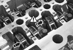
21.Oil the valve lifters (1) and install them in the order they were marked. NOTE! Check that the valve lifters are in contact with the valve stems. The illustration shows a valve lifter (2) in the wrong position.
22.Check that all the bearing surfaces on the camshafts, camshaft bearing caps and cylinder head have been carefully cleaned.
Lubricate the following: - Camshaft bearing surfaces and lobes - Cylinder head bearing surfaces - Camshaft bearing caps - Valve lifter rollers
Install the camshafts with markings (1) on the camshaft drive gears facing each other.
23.Install all camshaft bearing caps (A) as marked, except the front bearing cap (B) on the inlet camshaft. Tighten the screws until the bearing caps touch the camshafts. NOTE! The bearing caps are marked “I” (inlet) and “E” (Exhaust), and numbered 1-6 to facilitate assembly.
Carefully tighten the screws for caps 1-6 alternately, working from the center and outwards as in the figure, one turn at a time until the camshafts are fixed against the cylinder head.
Torque the screws as in the specification in
“Technical data”.
IMPORTANT! Make sure that the camshafts do not rotate during installation of the bearing caps.

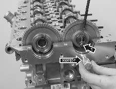
24.Put locking pin no. 9997007 in the cutout for the exhaust camshaft. Carefully turn the camshafts with a screwdriver in the high pressure or vacuum pump grooves (1) to facilitate installation of the lock pin.
IMPORTANT! The camshafts must not be turned more than needed to install the lock pin. There is a risk that the valves could be damaged.

25.Clean the front and rear bearing caps.
Apply liquid gasket 1161059-9, using roller no. 885511 on the gasket plane (1). The surface should be completely covered, without surplus.
Grease bearing race (2) on the front bearing caps.
Install the caps and torque the M10 and M6 screws to the values specified on the torque table in the “Technical Data”.

26.Install the inlet camshaft seal ring (1). Use tool no. 9997006 to press the seal ring in until the tool bottoms against the camshaft.
IMPORTANT! The seal ring dust lip will be damaged if it is stretched. If it has been incorrectly aligned or has been forced in, it must be changed.


